

ECU Main Relay 6. Main Fuse 30 A
http://moto.amoti.rtt/
FUEL
SYSTEM (DFI) 3-95
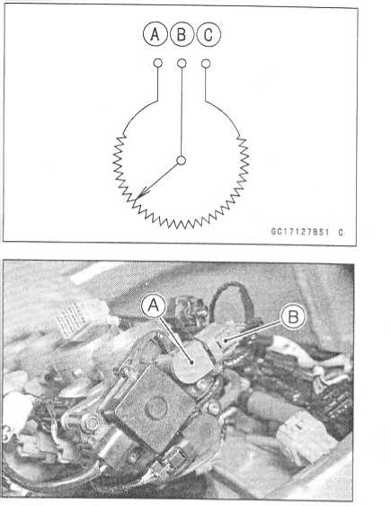
Subthrottle
Sensor (Service Code 32)
The
subthrottle sensor is a rotating variable resistor that change
output voltage according to throttle operating. The ECU senses this
voltage change and determines fuel injection quantity, and
ignition timing according to engine rpm, and throttle opening.
Input
Terminal [A]
Output
Terminal [B]
Ground
Terminal [C]
Subthrottle
Sensor Removal/Adjustment
CAUTION
Do
not remove or adjust the subthrottle sensor [A] since it has been
adjusted and set with precision at the factory.
Neverdrop
the sensor, especially on a hard surface. Such a shock to the sensor
can damage it. *
•
Subthrottle
Sensor Connector [B]
Input
Voltage Inspection
NOTE
O
Be
sure the battery is fully charged.
O
The
inspection is the same as “Input Voltage Inspection" of the
vacuum sensor and the atmospheric pressure sensor.
• Turn
the ignition switch OFF.
Remove the ECU (see this chapter). Do not disconnect the ECU connectors.
6CT7B110 P
http://mofo.amofi.rtt/
3-96
FUEL SYSTEM (DFI)
Subthrottle
Sensor (Service Code 32)
Connect
a digital voltmeter [A] to the connector [B], using
the
needle adapter set.
Special
Tool - Needle Adapter Set: 57001-1457
Subthrottle
Sensor Input Voltage
Connections
to ECU Connector
Meter
(+)-» BL lead (terminal 1)
Meter
(-)-» BR/BK lead (terminal 14)
Measure
the input voltage with the engine stopped, and
with
the connectors joined.
Turn
the ignition switch ON.
Input
Voltage at ECU Connector
Standard:
4.75 ~ 5.25 V DC
Turn
the ignition switch OFF.
If
the reading of input voltage is less than the standard,
check
the ECU for its ground, power supply and wiring
shorted.
If
the input voltage is within the standard range, check the
input
voltage at the subthrottle sensor connector.
Remove
the throttle body assembly temporarily (see
Throttle
Body Assy Removal).
Disconnect
the subthrottle sensor connector [A] and con-
nect
the harness adapter [B] between the harness con-
nector
and sub throttle sensor connector.
Connect
a digital meter to the harness adapter leads.
Special
Tool - Throttle Sensor Setting Adapter : 57001
-1538
Subthrottle
Sensor Input Voltage Connections to Sensor Meter (+)-> BL lead
Meter (-)-> BR/BK lead
Install
the throttle body assembly.
Measure
the sensor input voltage with the engine stopped, and with the
connector joined.
Turn
the ignition switch ON.
Input
Voltage at Sensor Standard: 4.75 ~ 5.25 V DC
Turn
the ignition switch OFF.
if
the reading is out of the range, check the wiring (see wiring
diagram in this section).
If
the reading is good, check the output voltage of the sensor.
http://moto.amoti.rtt/


Subthrottle
Sensor (Service Code 32)
FUEL
SYSTEM (DFI) 3-97
Output
Voltage Inspection
Measure
the output voltage at the ECU in the same way
as
input voltage inspection. Note the following.
Digital
Voltmeter [A]
Connector
[B]
Special
Tool - Needle Adapter Set: 57001-1457
Subthrottle
Sensor Output Voltage
Connections
to ECU
Meter
(+) -> BR lead (terminal 3)
Meter
(-) -» BR/BK lead (terminal 14)
Turn
the ignition switch ON.
Measure
the output voltage when the subthrottle valve is fully opened or
completely closed by hand.
Output
Voltage at ECU
1-08
- 4.60 V DC (at subthrottle Standard: . . „
NOTE
O
The
throttle sensor is operating correctly if the following voltages are
obtained:
•1.08
VDC (or slightly higher) with the subthrottle valve at the closed
position.
•
4.60
VDC (or slightly lower) with the subthrottle valve at the fully open
position.
CAUTION
*
★
Do
not remove or adjust the subthrottle sensor. It has been adjusted
and set with precision at the factory.
Never
drop the sensor can especially on a hard surface. A shock to
the sensor can damage it.
If
the output voltage is within the standard range, check the ECU for
a good ground, and power supply (see this chapter). If the ground
and power supply are good, replace the ECU.
★ If
the output voltage is far out of the standard range (e.g. when the
wiring is open, the reading is 0 V), check the output voltage again
at the sensor connector.

Valve full opening to closing)
http://moto.amoti.rtt/
3-98
FUEL SYSTEM (DFI) Subthrottle Sensor (Service Code 32)
Disconnect
the subthrottle sensor connector [A] and con-
nect
the harness adapter [B] between the harness con-
nector
and sub throttle sensor connector.
Connect
a digital meter to the harness adapter leads.
Special
Tool - Throttle Sensor Harness Adapter :
57001-1538
Subthrottle
Sensor Output Voltage
Connections
to Sensor
Meter
(+) -> BR lead
Meter
(-) BR/BK lead
Measure
the sensor output voltage with the engine
stopped,
and with the connector joined.
Turn
the ignition switch ON.
Measure
the output voltage when the subthrottle valve is
fully
opened or completely closed by hand.
Output
Voltage at Sensor
Standard: 1.08
- 4.60 V DC (at subthrottle valve
full
opening to closing)
NOTE
O
The
throttle sensor is operating correctly if the following voltages are
obtained:
•1.08
VDC (or slightly higher) with the subthrottle valve at the closed
position.
•
4.60
VDC (or slightly lower) with the subthrottle valve at the fully open
position.
CAUTION
Do
not remove or adjust the subthrottle sensor. It has been adjusted
and set with precision at the factory.
Never
drop the sensor, especially on a hard surface.
A
shock to the sensor can damage it.
NOTE
O
The
standard voltage marked with an asterisk refers to the value when
the voltage reading at the Input Voltage Inspection shows 5V
exactly.
O
When
the input voltage reading shows other than 5V, derive a voltage
range as follows.
Example:
In
the case of a input voltage of 4.75 V.
1.08
x 4.75
+ 5.00= 1.03 V 4.60 *4.75+
5.00 = 4.37 V Thus, the valid range is 1.03 - 4.37 V
After
subthrottle sensor voltage inspection, remove the harness adapter.
If
the reading is out of the standard range, inspect the throttle
sensor resistance.
If
the output voltage is normal, check the wiring for continuity
(see next diagram).
http://moto.amoti.ru/

FUEL
SYSTEM (DFI) 3-99
Subthrottle
Sensor (Service Code 32)
Resistance
Inspection
Turn
the ignition switch OFF.
Disconnect
the subthrottle sensor connector.
Connect
a digital meter [A] to the subthrottle sensor con-
nector
[B],
Measure
the main throttle sensor resistance.
Throttle
Sensor Resistance
Connections: BL
lead [C] <—>
BR/BK lead [D]
Standard: 4
- 6 kf2
If
the reading is out of the range, replace the throttle body
assy.
If
the reading is within the range, but the problem still
exists,
replace the ECU (see this chapter).
Subthrottle
Valve Actuator
Subthrottle
Sensor
Main
Throttle Sensor
http://moto.amoti.rtt/


3-100
FUEL SYSTEM (DFI)
Stick
Coils (#1, #2, #3, #4: Service Code 51, 52, 53, 54)
Stick
Coil #1: Ignition Coil (Service Code 51)
Stick
Coil #2: Ignition Coil (Service Code 52)
Stick
Coil #3: Ignition Coil (Service Code 53)
Stick
Coil #4: Ignition Coil (Service Code 54)
Removal/lnstallation
CAUTION
Never
drop the ignition coils, especially on a hard
surface.
Such a shock to the ignition coil can dam-
age
it.
See
Ignition System section in the Electrical System
chapter.
Input
Voltage Inspection
NOTE
o
Be
sure the battery is fully charged.
Turn
the ignition switch OFF.
Remove
the ECU (see this chapter). Do not disconnect
the
ECU connector.
Connect
a digital voltmeter [A] as shown, with the needle
adapter
set [B],
O
Measure the input voltage to each primary winding of the
ignition
coils with the engine stopped, and with the con-
nectors
joined.
Turn
the ignition switch ON.
Stick
Coil Input Voltage at ECU
Connections
for Stick Coil #1
Meter
(+) BK lead (terminal 39)
Meter
(-) -► BK/Y lead (terminal 51)
Connections
for Stick Coil #2
Meter
(+) ->■ BK/G lead (terminal 38)
Meter
(-) BK/Y lead (terminal 51)
Connections
for Stick Coil #3
Meter
(+) -> BK/W lead (terminal 37)
Meter
(-) -> BK/Y lead (terminal 51)
Connections
for Stick Coil #4
Meter
(+) -> BK/O lead (terminal 52)
Meter
(-) -> BK/Y lead (terminal 51)
Standard: Battery
Voltage (12.5 V or more)
If
the reading is out of the standard, check the wiring (see next
wiring diagram).
If
the reading is good, the input voltage is normal. Crank the engine,
and check the peak voltage of the stick coils (see Electrical
System chapter) in order to check the primary coils.
http://moto.amoti.ru/
Input Voltage at ecu

|
ON |
3 A R K |
||
IGNITION |
On |
|
||
BATTERY |
0-3 |
C |
pn |
|
16NITI OH |
0=3 |
|
|
|
T A |
L 1 |
0=3 |
|
|
T A |
L 2 |
0=1 |
c |
|
©
-
— BR — »
ry.si«
h
lJ*j
©
GC17H2BW3
C |
ECU |
5. Stick Coil #4 |
9 |
2. |
Stick Coil #1 |
6. Ignition Switch |
10 |
3. |
Stick Coil #2 |
7. Engine Stop Switch |
11 |
4. |
Stick Coil #3 |
8. Junction Box |
12 |


Ignition
Fuse 10 A Main Fuse 30 A Starter Relay Battery
http://moto.amoti.rtt/
3-102
FUEL SYSTEM (DFI)
Subthrottle
Valve Actuator (Service Code 62)
Subthrottle
Valve Actuator Removal
CAUTION ~
Do
not remove the subthrottle valve actuator [A]
since
it has been adjusted and set with precision
at
the factory.
Never
drop the actuator, especially on a hard sur-
face.
Such a shock to the actuator can damage it.
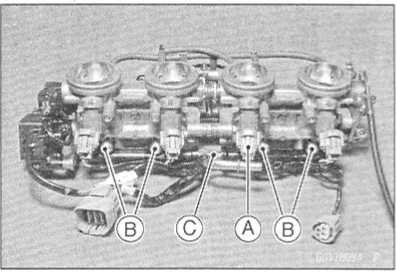
Subthrottle
Valve Actuator Inspection
Remove
the air cleaner housing (see Air Cleaner Housing
Removal).
Turn
the ignition switch ON.
Check
to see that all subthrottle valves [A] open and close
smoothly.
If
the subthrottle valves do not operate, check the actuator
internal
resistance (see Resistance Inspection).
Resistance
Inspection
Turn
the ignition switch OFR
Disconnect
the subthrottle valve actuator connector [A]. •
• Connect
a digital meter to the subthrottle valve actuator connector [A],
Measure the subthrottle valve actuator resistance.
Subthrottle Valve Actuator Resistance Connections: BK lead [1] <—» P lead [2]
G lead [3] <—» W/BL lead [4] Standard: About 5 - 7 f2
If the reading is out of the range, replace the throttle body assy.
If the reading is within the range, check the input voltage (see Input Voltage Inspection).

http://moto.amoti.ru/
FUEL
SYSTEM (DFI) 3-103
Subthrottle
Valve Actuator (Service Code 62)
Input
Voltage Inspection
NOTE
O
Be
sure the battery is fully charged.
Turn
the ignition switch OFF.
Connect
the peak voltage adaper [A] and a digital meter
to
the connector [C], using the needle adapter set [D].
Recommended
Tool - Peak Voltage Adapter
Type:
KEK-54-9-B
Brand:
KOWA SEIKI
Special
Tool - Needle Adapter Set: 57001-1457
Subthrottle
Valve Actuator Input Voltage
Connections
to Harness Connector
Meter
(+) -► BK/BL lead [1]
Meter
(-) -> P/BL lead [2]
Meter
(+) -» G lead [3]
Meter
(-) -> W/BL lead [4]
Measure
the actuator input voltage with the engine
stopped,
and with the connector joined.
Turn
the ignition switch ON.
Standard: about
8.5 ~ 10.5 V DC
If
the reading is out of the range, check the wiring to ECU (see
wiring diagram in this section).
If
the wiring is good, replace the ECU.
0
r—l«©
u cJrsi
r
O5oor-ioin«
i
i i i i i i i i i i i i i i i i i i i i i 11 in i i i i i i i 11 i i
i i i i i i i i i i i ill
i
i i i i i i i i i i i i i i i
h
i i ii 'i ii ii H" i i r
K
6CT7100M2
C
ECU
Subthrottle
Valve Actuator
Subthrottle
Sensor
Main
Throttle Sensor
http://moto.amoti.ru/

Input Voltage at Sensor


3-104
FUEL SYSTEM (DFI) Throttle
Grip and Cables
Free
Play Inspection
Refer
to the Throttle Control System Inspection in the Periodic
Maintenance chapter.
Free
Play Adjustment
Refer
to the Throttle Control System Inspection in the Periodic
Maintenance chapter.
Cable
Installation
Install
the throttle cables in accordance with the Cable Routing section in
the General Information chapter.
Install
the lower ends of the throttle cables in the cable bracket on the
throttle assy after installing the upper ends of the throttle
cables in the grip.
After
installation, adjust each cable properly.
Operation
with incorrectly routed or improperly adjusted cables could
result in an unsafe riding condition. *
•
Cable
Lubrication
•
Refer
to the General Lubrication Perform in the Periodic Maintenance
chapter.
A warning
http://moto.amoti.ru/
Choke
Cable
FUEL
SYSTEM (DFI) 3-105
Free
Play Inspection
Push
the choke lever [A] all the way to the front.
Check
choke cable free paly [B],
O
Determine the amount of choke cable play at the choke lever. Pull
the choke lever till just before the inner cable
moves
the link lever [D]; the amount of choke lever travel is the amount
of cable play.
If
the free play is incorrect, adjust the choke cable.
Choke
Cable Free Play
Standard: 2
- 3 mm (0.08 - 0.12 in)
Free
Play Adjustment
Loosen
the locknut [A], and turn the adjuster [B] until the cable has the
proper amount of free play.
Tighten
the locknut securely.
Choke
Cable Installation
Install
the choke cable in accordance with the Cable Routing section
in the General Information chapter.
After
installation, adjust the cable properly.
Operation
with an incorrectly routed or improperly adjusted cable could result
in an unsafe riding condition.
Cable
Lubrication
•
Refer
to the General Lubrication Perform in the Periodic Maintenance
chapter.


http://moto.amoti.ru/

3-106
FUEL SYSTEM (DFI) Throttle Body Assy
Idle
Speed Inspection
Refer
to the Idle Speed Inspection in the Periodic Maintenance
chapter.
Throttle
Bore Cleaning
Refer
to the Throttle Control System Inspection in the Periodic
Maintenance chapter.
Synchronization
Inspection
Refer
to the Engine Vacuum Synchronization Inspection in the Periodic
Maintenance chapter.
Synchronization
Adjustment
Refer
to the Engine Vacuum Synchronization Inspection in the Periodic
Maintenance chapter.
Throttle
Body Assy Removal
A WARNING
Gasoline
is extremely flammable and can be explosive under certain
conditions. Turn the ignition switch OFF. Disconnect the
battery (-) cable terminal. Do not smoke. Make sure the area is
well-ventilated and free from any source of flame or sparks; this
includes any appliance with a pilot light.
Be
prepared for fuel spillage: any spilled fuel must be completely
wiped up immediately. •
Remove:
Fuel
Tank (see Fuel Tank Removal)
Air
Cleaner Housing (see Air Cleaner Housing Removal)
Be
sure to place a piece of cloth around the fuel supply pipe [A] of
the throttle body assembly.
Remove:
Gray
Connectors [B]
Water
Temperature Sensor Connector [C]
Remove:
Vacuum
Switch Valve Vacuum Hose Vacuum Hose [A] (California model)
• Loosen:
Clamp Bolts [B]
Special Tool - Carburetor Drain Plug Wrench, Hex 3: 57001-1269
Remove the throttle body assembly [C] from holder.

http://moto.amoti.ru/
FUEL SYSTEM (DFI) 3-107
Throttle
Body Assy
Remove:
Choke
Cable Lower End [A]
Remove
the throttle case to make a throttle cable slack.
Remove:
Throttle
Cable Lower Ends [B]
•
After
removing the throttle body assy, stuff pieces of lint -free, clean
cloths into the throttle body holders.

Caution
If dirt gets into the engine, excessive engine wear and possible engine damage will occur. •
Throttle Body Assy Installation
Install the holder clamp bolts [A] in the direction as shown.
[B] Bolt Heads
Tighten:
Torque - Throttle Body Assembly Holder Clamp Bolts: 2.5 N-m (0.25 kgf-m, 22 in-lb)
Run the vacuum hoses as shown in the Cable, Wire, and Hose Routing section of the Appendix chapter.
When installing the fuel hose, refer to Fuel Tank Installation.

• Adjust:
Throttle Grip Free Play Choke Lever Free Play Idle Speed
http://moto.amoti.rtt/
3-108
FUEL SYSTEM (DFI) Throttle Body Assy
Throttle
Body Assy 5. Inlet Air Pressure Sensor Hoses
Injectors 6.
Bands
Injector
Connector Harness
Delivery
Pipe Assy
CAUTION
Do
not remove, disassemble or adjust the main throttle sensor,
subthrottle sensor, subthrottle valve actuator, throttle link
mechanism and throttle body assy, because they are adjust or set
surely at the manufacturer. Adjustment of these parts could result
in poor performance, requiring replacement of the throttle body
assy.
• Remove
the throttle body assembly (see Throttle Body Assy Removal).
Pressing the tabs [A] of each injector connectors, pull out the each connectors.
Remove the screws [B] to pull out the injector assys from the throttle body assy together with the delivery pipe [C].
NOTE
O Do not damage the part of insert of the injectors when they are pulled out from the throttle body.
http://moto.amoti.ru/
Throttle
Body Assy
FUEL
SYSTEM (DFI) 3-109
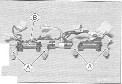
•
Pull
out the injectors [A] from the delivery pipe [Bj.
NOTE
O Do not damage the part of insert of the injectors when they are pulled out from the delivery pipe.
Throttle Body Assy Assembly
Before assembling, blow away dirt or dust from the throttle body and delivery pipe by applying compressed air.
Apply daphne oil or engine oil to the new O-rings [A] of each injector, insert them to the delivery pipe [B] and con- firm whether the injectors turn smoothly or not.
NOTE
O Replace the O-ring of injectors and the dust seals of delivery pipe to new one.

Apply daphne oil or engine oil to the new dust seals [A], in- sert the injectors installed to the delivery pipe to the throt- tle body.
NOTE
O Replace the dust seals of the throttle body to new one.
Install the delivery pipe assy to the throttle body.
Torque - Fuel Delivery Pipe Mounting Screws: 3.4 N-m (0.35 kgf-m, 30 in-lb) •
• Install the injector connectors to each injector, and bind the connector lead with clamps [A],
Insert the each hoses to the throttle body fittings.
Install the throttle body assy (see Throttle Body Assy Installation).

http://moto.amoti.rtt/
3-110
FUEL SYSTEM (DFI) Air Line
Element
Removal
•
Refer
to Air Cleaner Element Replacement in the Periodic Maintenance
chapter.
Element Installation
• Refer to Air Cleaner Element Replacement in the Periodic Maintenance chapter.
Air Cleaner Element Inspection
Visually check the element [A] for tears or breaks.
If the element has any tears or breaks, relay the element.

Oil Draining
A drain hose is connected to the bottom of the air cleaner part to drain water or oil accumulated in the cleaner part.
Visually check the catch tank [A] of the drain hose if the water or oil accumulates in tank.
If any water or oil accumulates in the tank, remove the tank from the drain hose and drain it.
A warning
Be sure reinstall the catch tank in the drain hose after draining. Oil on tires will make them slippery and can cause an accident and injury.

http://moto.amoti.ru/
FUEL
SYSTEM (DFI) 3-111
Air
Inlet Duct Installation •
Tighten:
Torque
- Air Inlet Duct Mounting Bolts: 6.9 N-m (0.70 kgf-m, 61 in-lb)
http://moto.amoti.rtt/Air Line

3-112
FUEL SYSTEM (DFI) Fuel Tank
Fuel
Tank Removal
Gasoline
is extremely flammable and can be explosive under certain
conditions. Make sure the area is well-ventilated and free from any
source of flame or sparks; this includes any appliance with a pilot
light. Do not smoke. Turn the ignition switch OFF. Be prepared for
fuel spillage; any spilled fuel must be completely wiped up
immediately.
CAUTION
For
California model, if gasoline, solvent, water or any other liquid
enters the canister, the canister’s vapor absorbing capacity is
greatly reduced. If the canister does become contaminated, replace
it with a new one.
Remove:
Seats
(see Frame chapter)
Fuel
Tank Bolts [A]
Drain
Hose [B]
Open
the fuel tank cap to lower the pressure in the tank.
Disconnect
the fuel pump lead connector [A],
Be
sure to place a piece of cloth around the fuel hose joint [B],
While
pinching the hose joint locks [C] with fingers, pull the joint out
along the delivery pipe.
A
WARNING
Be
prepared for fuel spillage; any spilled fuel must be completely
wiped up immediately.
When
the fuel hose is disconnected, fuel spills out from the hose and the
pipe because of residual pressure. Cover the hose connection with a
piece of clean cloth to prevent fuel spillage. •
•
Remove
the fuel tan, and place it on a flat surface.A warning

http://moto.amoti.ru/
Fuel
Tank
FUEL
SYSTEM (DFI) 3-113
•
For
California Model, note the following:
O Be sure to plug the evaporative fuel return hose to prevent fuel spilling before fuel tank removal.
A WARNING
For California model, be careful not to spill the gasoline through the return hose. Spilled fuel is hazardous.
★ If liquid or gasoline flows into the breather hose, remove the hose and blow it clean with compressed air (California model).
O Be careful of fuel spillage from the fuel tank since fuel still remains in the fuel tank and fuel pump.
A WARNING
Store the fuel tank in an area which is well -ventilated and free from any source of flame or sparks. Do not smoke in this area. Place the fuel tank on a flat surface and plug the fuel pipes to prevent fuel leakage. •
Fuel Tank Installation
Note the above WARNING (see Fuel Tank Removal).
Route the hoses correctly (see Appendix chapter).
Check that the rubber dampers [A] are on the air cleaner housing.
Check that the dampers [A] are in place on the fuel tank as well.
If the dampers are damaged or deteriorated, replace them.
If the dampers are damaged or deteriorated, replace them.
• For California Model, note the following:
oTo prevent the gasoline from flowing into or out of the canister, hold the separator perpendicular to the ground.
O Connect the hoses according to the diagram of the system (see Cable, Wire, and Hose Routing section in the Appendix chapter). Make sure they do not get pinched or kinked.
O Route hoses with a minimum of bending so that the air or vapor will not be obstructed.

http://moto.amoti.rtt/
3-114
FUEL SYSTEM (DFI) Fuel Tank
Connect
the fuel pump lead connector [A],
Insert
the fuel hose joint [B] straight onto the delivery pipe
until
the hose joint clicks.
Push
and pull [C] the hose joint [B] back and forth, and
make
sure it is locked and does not come off. When the
hose
joint is correctly installed, it should slide on the de-
livery
pipe about 5 mm (0.2 in.).
If
it does not slide, reinstall the hose joint.
Make
sure the hose joint is installed correctly on the delivery pipe by
sliding the joint, or the fuel could leak.
Fuel
Tank Inspection
Remove
the hose(s) from the fuel tank, and open the tank
cap.
Check
to see if the water drain pipe [B] and fuel breather
pipe
[C] in the tank are not clogged. Check the tank cap
breather
also.
If
they are clogged, remove the tank and drain it, and then
blow
the breather free with compressed air.
CAUTION ~
Do
not apply compressed air to the air vent holes
Fuel
Tank Cleaning
Clean
the tank in a well-ventilated area, and take care that there are no
sparks or flame anywhere near the working area. Because of the
danger or highly flammable liquids, do not use gasoline or low flash
point solvents to clean the tank. •
Remove
the fuel tank (see Fuel Tank Removal).
Drain
the fuel.
Remove
the fuel pump assy.
Pour
some high flash-point solvent into the fuel tank and shake the tank
to remove dirt and fuel deposits.
Pour
the solvent over of the tank.
• Dry
the tank with compressed air.
A warning

In the tank cap. This could cause damage and clogging of the labyrinth in the cap.
A warning
Install the fuel pump assy (see Fuel Pump Installation).
Install the fuel tank (see Fuel Tank Installation).

http://moto.amoti.ru/
Evaporative
Emission Control System
FUEL
SYSTEM (DFI) 3-115
The
Evaporative Emission Control System routes fuel vapors from the
fuel system into the running engine or stores the vapors in a
canister when the engine is stopped. Although no adjustments
are required, a thorough visual inspection must be made at the
intervals specified by the Periodic Maintenance Chart.
Parts
Removal/lnstallation
Gasoline
is extremely flammable and can be explosive under certain
conditions. Turn the ignition switch OFF. Do not smoke. Make sure
the area is well-ventilated and free from any source of flame or
sparks; this includes any appliance with a pilot light.
CAUTION
If
gasoline, solvent, water or any other liquid enters the canister,
the canister’s vapor absorbing capacity is greatly reduced.
If the canister does become contaminated, replace it with a new one.
•
To
prevent the gasoline from flowing into or out of the canister, hold
the separator perpendicular to the ground.
Connect
the hoses according to the diagram of the system. Make sure
they do not get pinched or kinked.
Hose
Inspection
Refer
to the Evaporative Emission Control System Inspection in the
Periodic Maintenance chapter.
Separator
Inspection
• Refer
to the Evaporative Emission Control System Inspection in the
Periodic Maintenance chapter.A warning
[A] Separator

http://moto.amoti.ru/
3-116
FUEL SYSTEM (DFI) Evaporative Emission Control System
Separator
Operation Test
Gasoline
is extremely flammable and can be ex-
plosive
under certain conditions. Turn the ignition
switch
OFF. Do not smoke. Make sure the area is
well-ventilated
and free from any source of flame
or
sparks; this includes any appliance with a pilot
light.
Connect
the hoses to the separator, and install the sepa-
rator
on the motorcycle.
Disconnect
the breather hose from the separator, and in-
ject
about 20 ml_ of gasoline [A] into the separator [B]
through
the hose fitting.
Disconnect
the fuel return hose [C] from the fuel tank [D],
Run
the open end of the return hose into the container
and
hold it level with the tank top [E].
Start
the engine, and let it idle.
If
the gasoline in the separator comes out of the hose, the
separator
works well. If it does not, replace the separator
with
a new one.
Canister
Inspection (California Model Only)
•
Refer
to the Evaporative Emission Control System In-A warning

NOTE
o The canister [A] is designed to work well through the motorcycle’s life without any maintenance if it is used under normal conditions.

http://moto.amoti.ru/
COOLING
SYSTEM 4-1
Exploded
View 4-2
Specifications
4-4
Special
Tool 4-5
Coolant
Flow Chart 4-6
Coolant
4-9
Coolant
Deterioration Inspection 4-9
Coolant
Level Inspection 4-9
Coolant
Draining 4-9
Coolant
Filling 4-9
Pressure
Testing 4-10
Cooling
System Flushing 4-10
Coolant
Filter Cleaning 4-11
Coolant
Reserve Tank Removal 4-11
Coolant
Reserve Tank Installation 4-11
Water
Pump . 4-12
Water
Pump Removal 4-12
Water
Pump Installation 4-12
Water
Pump Impeller Disassembly/Assembly 4-12
Water
Pump Inspection 4-12
Water
Pump Housing Disassembly 4-13
Water
Pump Housing Assembly 4-13
Mechanical
Seal Inspection 4-14
Radiator,
Radiator Fan 4-15
Radiator
and Radiator Fan Removal 4-15
Radiator
and Radiator Fan Installation 4-16
Radiator
Inspection 4-16
Radiator
Cap Inspection 4-17
Radiator
Filler Neck Inspection 4-18
Thermostat
4-19
Thermostat
Removal 4-19
Thermostat
Installation 4-19
Thermostat
Inspection 4-19
Hose
and Pipes 4-21
Hose
Installation 4-21
Hose
Inspection 4-21
Radiator
Fan Switch, Water Temperature Sensor 4-22
Radiator
Fan Switch, Water Temperature Sensor Removal 4-22
Radiator
Fan Switch, Water Temperature Sensor Installation 4-22
Radiator
Fan Switch, Water Temperature Sensor Inspection 4-22
http://moto.amoti.rtt/Cooling System table of contents
4-2
COOLING SYSTEM
Exploded
View
c
http://moto.amoti.ru/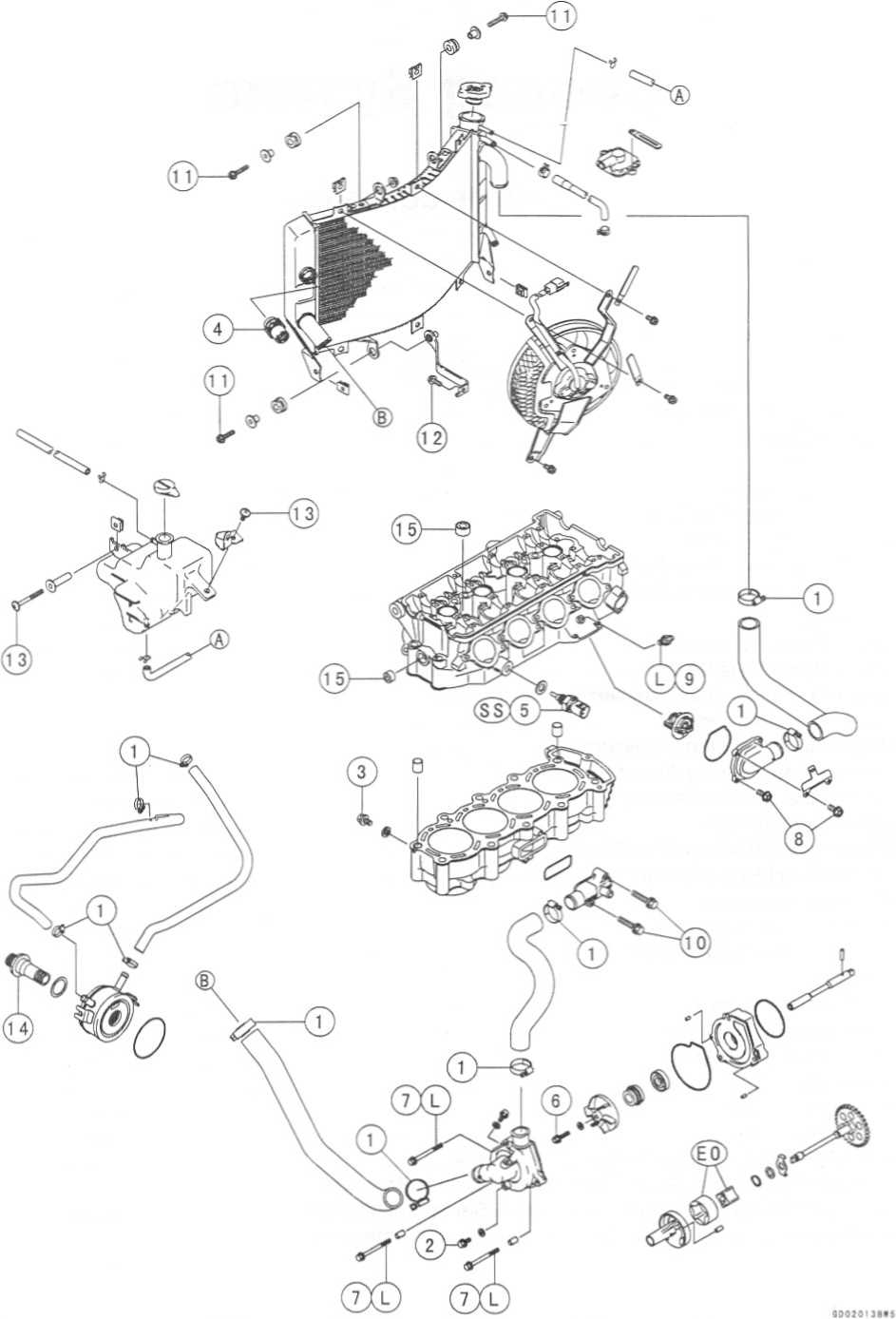
No. |
Fastener |
Torque |
Remarks |
||
N-m |
kgf-m |
ft-lb |
|||
1 |
Water hose clamp screws |
2.0 |
0.20 |
17 in-lb |
|
2 |
Coolant drain plug (water pump) |
8.8 |
0.90 |
78 in-lb |
|
3 |
Coolant drain plug (cylinder) |
8.8 |
0.90 |
78 in-lb |
|
4 |
Radiator fan switch |
18 |
1.8 |
13 |
|
5 |
Water temperature sensor |
25 |
2.5 |
18 |
SS |
6 |
Water pump impeller bolt |
9.8 |
1.0 |
87 in-lb |
|
7 |
Water pump cover bolts |
12 |
1.2 |
104 in-lb |
L |
8 |
Thermostat housing cover bolts |
5.9 |
0.60 |
52 in-lb |
|
9 |
Coolant by-pass fitting |
8.8 |
0.90 |
78 in-lb |
L |
10 |
Water hose fitting bolts |
12 |
1.2 |
106 in-lb |
|
11 |
Radiator mounting bolts |
6.9 |
0.70 |
61 in-lb |
|
12 |
Radiator bracket mounting bolts |
6.9 |
0.70 |
61 in-lb |
|
13 |
Coolant reserve tank mounting screws |
6.9 |
0.70 |
61 in-lb |
|
14 |
Oil cooler bolt |
78 |
8.0 |
58 |
|
15 |
Water passage plugs |
20 |
2.0 |
14 |
|
L:
Apply a non-permanent locking agent.
EO:
Apply engine oil.
SS:
Apply silicone sealant (Kawasaki Bond: 56019-120).
http://moto.amoti.ru/
Item |
Standard |
Coolant provided when shipping: Type Color Mixed ratio Freezing point Total amount |
Permanent type of antifreeze (soft water and ethylene glycol plus corrosion and rust inhibitor chemicals for aluminum engines and radiators) Green Soft water 50%, coolant 50% -35=C (-31=F) 2.4 L (2.5 US qt.) (reserve tank full level including radiator and engine) |
Radiator cap Relief pressure: |
93 ~ 123 kPa (0.95 ~ 1.25 kgf/cm2, 14- 18 psi) |
Thermostat: Valve opening temperature Valve full opening lift |
58 - 62°C (136 ~ 144 CF) 8 mm (0.3 in.) or more @75°C (167 °F) |
http://mofo.amofi.rtt/
COOLING
SYSTEM 4-5
Kawasaki
Bond (Silicone Sealant) : 56019-120
http://moto.amoti.rtt/Special Tool

Permanent
type antifreeze is used as a coolant to protect the cooling system
from rust and corrosion. When the engine starts, the water pump
turns and the coolant circulates.
The
thermostat is a wax pellet type which opens or closes with coolant
temperature changes. The thermostat continuously changes its valve
opening to keep the coolant temperature at the proper level. When
coolant temperature is below 58 - 62'C
(136-144°F), the thermostat closes so that the coolant flow is
restricted through the air bleeder hole, causing the engine to warm
up more quickly. When coolant temperature is more than 58 - 62"C
(136 - 144=F),
the thermostat opens and the coolant flows.
When
the coolant temperature goes up beyond 92 ~ 104 C (198 - 219 F), the
radiator fan switch conducts to operate the radiator fan. The
radiator fan draws air through the radiator core when there is not
sufficient air flow such as at low speeds. This increases up the
cooling action of the radiator. When the temperature goes down from
the operation temperature by 3 - 8°C (37 - 46°F), the fan switch
opens and the radiator fan stops.
In
this way, this system controls the engine temperature within narrow
limits where the engine operates most efficiently even if the
engine load varies.
The
system is pressurized by the radiator cap to suppress boiling and
the resultant air bubbles which can cause engine overheating. As the
engine warms up, the coolant in the radiator and the water jacket
expands. The excess coolant flows through the radiator cap and hose
to the reserve tank to be stored there temporarily. Conversely, as
the engine cools down, the coolant in the radiator and the water
jacket contracts, and the stored coolant flows back to the radiator
from the reserve tank.
The
radiator cap has two valves. One is a pressure valve which holds the
pressure in the system when the engine is running. When the pressure
exceeds 93 - 123 kPa (0.95 - 1.25 kgf/cm2,
14-18
psi),
the pressure valve opens and releases the pressure to the reserve
tank. As soon as pressure escapes, the valve closes, and keeps the
pressure at 93 - 123 kPa (0.95 - 1.25 kgf/cm2,
14-18
psi). When the engine cools down, another small valve (vacuum valve)
in the cap opens. As the coolant cools, the coolant contracts to
form a vacuum in the system. The vacuum valve opens and allows the
coolant from the reserve tank to enter the radiator.
http://moto.amoti.ru/6 Cooling system Coolant Flow Chart
COOUNG
SYSTEM 4-7
Coolant
Flow Chart
Radiator
Radiator
Cap
Radiator
Fan
Fan
Switch
Drain
Plugs
Water
Pump
Water
Temperature Sensor
Oil
Cooler
Thermostat
When
the engine is cold, the thermostat is closed so that the coolant
flow is restricted through the air bleeder hole, causing the engine
to warm up more quickly.
By-pass
Fitting
The
fitting is installed to bleed the air.
http://moto.amoti.ru/
4-8
COOLING SYSTEM
Coolant
Flow Chart
Reserver
Tank
When
the engine is very hot, the pressure valve in the radiator cap
allows air and vapor to escape into the reserve tank. When the
engine cools down, the pressure drop draws the vacuum valve (another
small valve) open, admitting coolant from the reserve tank into the
radiator.
http://moto.amoti.rtt/
Coolant
COOLING
SYSTEM 4-9
Coolant
Deterioration Inspection
Visually
inspect the coolant in the reserve tank.
If
whitish cotton-like wafts are observed, aluminum parts
in
the cooling system are corroded. If the coolant is
brown,
iron or steel parts are rusting. In either case, flush
the
cooling system.
If
the coolant gives off an abnormal smell, check for a
cooling
system leak. It may be caused by exhaust gas
leaking
into the cooling system.
Coolant
Level Inspection
NOTE
O
Check
the level when the engine is cold (room or ambi-
ent
temperature).
Check
the coolant level in the reserve tank with the mo-
torcycle
held perpendicular.
If
the coolant level is lower than the low level line [A], add
coolant
to the full level line [B],
CAUTION
For
refilling, add the specified mixture of coolant and soft water.
Adding water alone dilutes the coolant and degrades its
anticorrosion properties. The diluted coolant can attack the
aluminum engine parts. In an emergency, soft water alone can be
added. But the diluted coolant must be returned to the correct
mixture ratio within a few days.
Coolant
Draining
Refer
to the Cooling System in the Periodic Maintenance chapter.
Coolant
Filling
• Refer
to the Cooling System in the Periodic Maintenance chapter.
If coolant must be added often, or the reservoir tank has run completely dry, there is probably leakage in the cooling system. Check the system for leaks. * •

http://moto.amoti.ru/
4-10
COOLING SYSTEM
Coolant
Pressure
Testing
Remove:
Right
Inner Cover (see Frame chapter)
Remove
the radiator cap, and install a cooling system
pressure
tester [A] on the filler neck.
NOTE
O
Wet
the cap sealing surfaces with water or coolant to
prevent
pressure leaks.
Build
up pressure in the system carefully until the pres-
sure
reaches 123 kPa (1.25 kgf/cm2,
18 psi).
CAUTION
[
’ '
During
pressure testing, do not exceed the pressure for which the
system is designed. The maximum pressure is 123 kPa (1.25
kgf/cm2,
18 psi). •
Watch
the gauge for at least 6 seconds.
If
the pressure holds steady, the system is all right.
If
the pressure drops and no external source is found, check for
internal leaks. Droplets in the engine oil indicate internal
leakage. Check the cylinder head gasket and the water pump.
Remove
the pressure tester, replenish the coolant, and install the
radiator cap.
Cooling
System Flushing
Over
a period of time, the cooling system accumulates rust, scale, and
lime in the water jacket and radiator. When this accumulation is
suspected or observed, flush the cooling system. If this
accumulation is not removed, it will clog up the water passage and
considerable reduce the efficiency of the cooling system.
Drain
the cooling system (see Cooling System in the Periodic
Maintenance chapter).
Fill
the cooling system with fresh water mixed with a flushing
compound.
CAUTION
Do
not use a flushing compound which is harmful to the aluminum engine
and radiator. Carefully follow the instructions supplied by the
manufacturer of the cleaning product.
• Warm
up the engine, and run it at normal operating temperature for
about ten minutes.

Stop the engine, and drain the cooling system.
Fill the system with fresh water.
Warm up the engine and drain the system.
Repeat the previous two steps once more.
Fill the system with a permanent type coolant and bleed the air from the system (see Cooling System in the Periodic Maintenance chapter).
http://moto.amoti.ru/
Coolant
COOLING
SYSTEM 4-11
Coolant
Filter Cleaning
•
Refer
to the Fuel System in the Periodic Maintenance chapter.
Coolant Reserve Tank Removal • Remove:
Coolant Reserve Tank Mounting Screws [A]
• Remove:
Coolant Reserve Tank Mountinq Screws [Al Collar
Idle Adjuster Bracket [B]
Coolant Reserve Tank [C]
Coolant Reserve Tank Installation
Install:
Coolant Reserve Tank [A]
Collar [B]
Idle Adjuster Bracket [C]
Tighten:
Torque - Coolant Reserve Tank Mounting Screws [D]: 6.9 N-m (0.70 kgf-m, 61 in-lb)

http://moto.amoti.rtt/
4-12
COOLING SYSTEM
Water
Pump
Water
Pump Removal
•
Refer
to the Oil Pump Removal in Engine Lubrication System chapter.
Water Pump Installation
• Refer to the Oil Pump Installation in Engine Lubrication System chapter.
Water Pump Impeller Disassembly/Assembly
The sealing seat and rubber seal may be removed easily by hand.
Apply coolant around the surfaces of the rubber seal and sealing seat.
Install the rubber seal [A] and sealing seat [B] into the impeller by pressing them by hand until the seat stops at the bottom of the hole.
Tighten the water pump impeller bolt by special torque. Torque - Water Pump Impeller Bolt: 10 N m (1.0 kgfm, 87
in-lb)
Water Pump Inspection
Check the drainage outlet passage [A] at the bottom of the water pump body for coolant leaks.
If the mechanical seal is damaged, the coolant leaks through the seal and drains through the passage. Replace the water pump unit. •

• Visually inspect the impeller [A].
If the surface is corroded, or if the blades are damaged, replace the impeller.

http://moto.amoti.rtt/
Water
Pump
COOLING
SYSTEM 4-13
Water
Pump Housing Disassembly
CAUTION
Do
not damage the hole wall of the water pump
housing.
•
Insert
a bar [A] into the pump housing [B], and hammer

• Take the oil seal [A] out of the housing [B] with a hook [C],

Water Pump Housing Assembly
CAUTION
Do not reuse the mechanical seal and oil seal.
Apply high temperature grease to the oil seal lips [A],
Press the new oil seal into the housing with a bearing driver [B] until it stops at the bottom surface [C] of the housing.
Special Tool - Bearing Driver Set: 57001-1129
GD0601 BBS 1 C

CAUTION
Be careful not to damage the sealing surface of the •
| mechanical seal.
• Press the new mechanical seal into the housing with stem bearing driver [A] until its flange [B] touches the surface
of the housing.
Special Tool - Bearing Driver: 57001-382

http://moto.amoti.ru/
4-14
COOLING SYSTEM
Water
Pump
Mechanical
Seal Inspection
Visually
inspect the mechanical seal.
If
any one of the parts is damaged, replace the mechani-
cal
seal as a unit.
Impeller
Sealing Seat Surface
Rubber
Seal
Mechanical
Seal
http://moto.amoti.rtt/

COOLING
SYSTEM 4-15
Radiator
and Radiator Fan Removal
The
radiator fan is connected directly to the battery. The radiator
fan may start even if the ignition switch is off. NEVER TOUCH THE
RADIATOR FAN UNTIL THE RADIATOR FAN CONNECTOR IS DISCONNECTED.
TOUCHING THE FAN BEFORE THE CONNECTOR IS DISCONNECTED COULD CAUSE
INJURY FROM THE FAN BLADES. *
•
•
Remove:Radiator, Radiator Fan
A warning
Lower Fairings (see Frame chapter)
Coolant (see Cooling System in the Periodic Maintenance chapter)
Radiator Hoses [A]
Radiator Mounting Bolt [B]
• Remove:
Fan Switch Lead Connector [A] Radiator Hose [B]
• Remove:
Radiator Mounting Bolts [A] Radiator Fan Lead Connector Radiator [B]

http://moto.amoti.ru/
4-16
COOLING SYSTEM
•
Remove:Radiator, Radiator Fan
Radiator Fan Mounting Bolts [A]
Radiator Fan [B]
CAUTION
Do not touch the radiator core. This could damage the radiator fins, resulting in loss of cooling effi- ciency. ★

Radiator and Radiator Fan Installation
Install:
Radiator [A]
Dampers [B] (note the direction)
Collars [C]
Horn [D]
Bracket [E]
Tighten:
Torque - Radiator Bracket Mounting Bolts (L= 16 mm) [F]:
N-m (0.70 kgf-m, 61 in-lb)
Radiator Mounting Bolts (L= 30 mm) [GJ: 6.9 N-m (0.70 kgf-m, 61 in-lb)
Radiator Mounting Bolts (L= 25 mm) [H]: 6.9 N-m (0.70 kgf-m, 61 in-lb)

Radiator Inspection
Check the radiator core.
★ If there are obstructions to air flow, remove them.
If the corrugated fins [A] are deformed, carefully straighten them.
If the air passages of the radiator core are blocked more than 20% by unremovable obstructions or irreparably deformed fins, replace the radiator with a new one.

http://moto.amoti.ru/
COOLING
SYSTEM 4-17
CAUTION
When
cleaning the radiator with steam cleaner, be careful of the
following to prevent radiator damage. Keep the steam gun [A] away
more than 0.5 m (1.6 ft) [B] from the radiator core.
Hold
the steam gun perpendicular [C] (not oblique [D]) to the core
surface.
Run
the steam gun following the core fin direction.
Radiator
Cap Inspection
Check
the condition of the bottom [A] and top [B] valve seals and valve
spring [C].
If
any one of them shows visible damage, replace the cap with a new
one.
•
Install
the cap [A] on a cooling system pressure tester [B],Radiator, Radiator Fan


NOTE
O Wet the cap sealing surfaces with water or coolant to prevent pressure leaks. •

• Watching the pressure gauge, pump the pressure tester to build up the pressure until the relief valve opens: the gauge hand flicks downward. Stop pumping and measure leak time at once. The relief valve must open within the specified range in the table below and the gauge hand must remain within the same range at least 6 seconds.
Radiator Cap Relief Pressure Standard: 93 ~ 123 kPa (0.95
psi)
1.25 kgf/cm2,
14 ~ 18
★ If the cap cannot hold the specified pressure, or if it holds too much pressure, replace it with a new one.
http://moto.amoti.ru/
4-18
COOLING SYSTEM Radiator, Radiator Fan
Radiator
Filler Neck Inspection
Remove
the right inner cover (see Frame chapter).
Remove
the radiator cap.
Check
the radiator filler neck for signs of damage.
Check
the condition of the top and bottom sealing seats [A] in the filler
neck. They must be smooth and clean for the radiator cap to
function properly.
http://moto.amoti.rtt/

Thermostat
COOLING
SYSTEM 4-19
Thermostat
Removal
Remove:
Coolant
(see Cooling System in the Periodic Maintenance chapter)
Seats
(see Frame chapter)
Fuel
Tank (see Fuel System chapter)
Thermostat
Housing Cover Bolts [A]
Bracket
[B]
Thermostat
Housing Cover [C]
Thermostat
Thermostat
Installation
Be
sure to install the O-ring [A] on the housing cover.
Tighten
the housing cover bolts.
Torque
- Thermostat Housing Cover Bolts: 5.9 N-m (0.60 kgf-m, 52 in-lb)
Fill
the radiator with coolant.
Thermostat
Inspection
Remove
the thermostat, and inspect the thermostat valve [A] at room
temperature.
If
the valve is open, replace the thermostat with a new one.
http://moto.amoti.rtt/

4-20
COOLING SYSTEM
Thermostat
To
check valve opening temperature, suspend the thermostat [A] in
a container of water and raise the temperature of the water.
O
The thermostat must be completely submerged and must not touch the
container sides or bottom. Suspend an accurate thermometer [B]
in the water so that the heat sensitive portions [C] are
located in almost the same depth. It must not touch the container,
either.
If
the measurement is out of the specified range, replace the
thermostat with a new one.
Thermostat
Valve Opening Temperature 58 - 62°C (136 ~ 144°F)
http://moto.amoti.rtt/

Hose
and Pipes
COOLING
SYSTEM 4-21
Hose
Installation
Install
the hoses and pipes being careful to follow bending direction
or diameter. Avoid sharp bending, kinking, flattening, or twisting.
Install
the clamps [A] as near as possible to the hose end to clear the
raised rib or the fitting. This will prevent the hoses from working
loose.
oThe
clamp screws should be positioned correctly to prevent the
clamps from contacting anything.
Torque
- Hose Clamp Screws: 2.0 N-m (0.20 kgf-m, 17 in-lb)
Hose
Inspection
o
Refer to the Cooling System in the Periodic Maintenance chapter
http://moto.amoti.rtt/

4-22
COOLING SYSTEM
Radiator
Fan Switch, Water Temperature Sensor
Radiator
Fan Switch, Water Temperature Sensor
Removal
The
fan switch or the water temperature sensor
should
never be allowed to fall on a hard surface.
Such
a shock to their parts can damage them.
Drain
the coolant (see Cooling System in the Periodic
Maintenance
chapter).
Remove:
Radiator
Fan Switch Lead Connector [A]
Radiator
Fan Switch [B]
•
Remove:Caution

Seats (see Frame chapter)
Fuel Tank (see Fuel System chapter)
Water Temperature Sensor Lead Connector [A] Water Temperature Sensor [B]

Radiator Fan Switch, Water Temperature Sensor Installation
Apply silicone sealant to the threads of the water temperature sensor.
Sealant - Kawasaki Bond (Silicone Sealant): 56019-120
Tighten the fan switch and water temperature sensor. Torque - Radiator Fan Switch : 18 N-m (1.8 kgf-m, 13 ft-lb)
Water Temperature Sensor: 25 N-m (2.5 kgf-m, 18 ft-lb)
Fill the coolant.and bleed the air from cooling system (see Cooling System in the Periodic Maintenance chapter).
Radiator Fan Switch, Water Temperature Sensor Inspection
Refer to the Electrical System chapter for these inspections.
http://moto.amoti.ru/
ENGINE
TOP END 5-1
Exploded
View 5-2
Specifications
5-6
Special
Tools and Sealant 5-8
Clean
Air System 5-10
Air
Suction Valve Removal 5-10
Air
Suction Valve Installation 5-10
Air
Suction Valve Inspection 5-10
Vacuum
Switch Valve Removal 5-10
Vacuum
Switch Valve Installation .... 5-10
Vacuum
Switch Valve Test 5-11
Clean
Air System Hose Inspection .. 5-11
Cylinder
Head Cover 5-12
Cylinder
Head Cover Removal 5-12
Cylinder
Head Cover Installation 5-13
Camshaft
Chain Tensioner 5-14
Camshaft
Chain Tensioner
Removal
5-14
Camshaft
Chain Tensioner
Installation
5-14
Camshaft,
Camshaft Chain 5-15
Camshaft
Removal 5-15
Camshaft
Installation 5-15
Camshaft,
Camshaft Cap Wear 5-17
Camshaft
Runout 5-17
Cam
Wear 5-18
Camshaft
Chain Removal 5-18
Camshaft
and Sprocket Assembly... 5-18
Cylinder
Head 5-19
Cylinder
Compression
Measurement
5-19
Cylinder
Head Removal 5-20
Cylinder
Head Installation 5-21
Cylinder
Head Warp 5-21
Valves
5-22
Valve
Clearance Inspection 5-22
Valve
Clearance Adjustment 5-22
Valve
Removal 5-22
Valve
Installation 5-22
Valve
Guide Removal 5-22
Valve
Guide Installation 5-23
Valve-to-Guide
Clearance Measurement (Wobble Method).... 5-23
Valve
Seat Inspection 5-24
Valve
Seat Repair 5-24
Cylinder,
Pistons 5-30
Cylinder
Removal 5-30
Cylinder
Installation 5-30
Piston
Removal 5-30
Piston
Installation 5-31
Cylinder
Wear 5-32
Piston
Wear 5-32
Piston
Ring, Piston Ring Groove
Wear
5-33
Piston
Ring Groove Width 5-33
Piston
Ring Thickness 5-34
Piston
Ring End Gap 5-34
Throttle
Valve Holder 5-35
Throttle
Valve Holder Installation 5-35
Muffler
5-36
Exhaust
Pipe Manifold Removal 5-36
Exhaust
Pipe Manifold Installation... 5-36
Muffler
Body Removal 5-36
Muffler
Body Installation 5-36
http://mofo.amofi.ru/
Engine Top End table of contents
5-2
ENGINE TOP END
Exploded
View
http://moto.amoti.rtt/

No. |
Fastener |
Torque |
Remarks |
||
N-m |
kgf-m |
ft lb |
|||
1 |
Air suction valve cover bolts |
12 |
1.2 |
104 in-lb |
L |
2 , |
Cylinder head cover bolts |
9.8 |
1.0 |
87 in-lb |
|
3 |
Spark plugs |
13 |
1.3 |
113 in-lb |
|
4 |
Camshaft cap bolts |
12 |
1.2 |
104 in-lb |
S |
5 |
Cylinder head bolts (9 mm) |
40 |
4.1 |
30 |
|
6 |
Cylinder head bolts (6 mm) |
12 |
1.2 |
104 in-lb |
S |
7 |
Cylinder head jacket plug (upper) |
20 |
2.0 |
14.5 |
L |
8 |
Cylinder head jacket plug (left) |
20 |
2.0 |
14.5 |
L |
9 |
Coolant by-pass fitting |
8.8 |
0.90 |
78 in-lb |
L |
10 |
Water temperature sensor |
25 |
2.5 |
18 |
SS |
11 |
Camshaft position sensor bolt |
12 |
1.2 |
104 in-lb |
|
12 |
Throttle body assembly holder bolts |
12 |
1.2 |
104 in-lb |
|
13 |
Throttle body assembly holder clamp bolts |
2.5 |
0.25 |
22 in-lb |
|
14 |
Camshaft sprocket bolts |
15 |
1.5 |
11 |
L |
15 |
Front camshaft chain guide bolt (upper) |
25 |
2.5 |
18 |
|
16 |
Front camshaft chain guide bolt (lower) |
12 |
1.2 |
104 in-lb |
|
17 |
Rear camshaft chain guide bolt |
25 |
2.5 |
18 |
|
18 |
Camshaft chain tensioner mounting bolts |
9.8 |
1.0 |
87 in-lb |
|
19 |
Camshaft chain tensioner cap bolt |
29 |
3.0 |
21 |
|
20.
Closed coil end faces downward.
G:
Apply grease.
L:
Apply a non-permanent locking agent. M: Apply molybdenum disulfide
grease.
EO:
Apply engine oil.
SS:
Apply silicone sealant.
R:
Replacement Parts
S:
Follow the specific tightening sequence.
http://moto.amoti.rtt/
5-4
ENGINE TOP END
Exploded
View

No. |
Fastener |
Torque |
Remarks |
||
N-m |
kgf-m |
ft-lb |
|||
1 |
Water jacket drain bolt |
8.8 |
0.90 |
78 in-lb |
|
2 |
Exhaust pipe manifold nut |
17 |
1.7 |
12 |
|
3 |
Exhaust pipe clamp bolt |
17 |
1.7 |
12 |
|
4 |
Muffler body bolt |
30 |
3.0 |
22 |
|
5 |
Crankshaft sensor cover bolts |
9.8 |
1.0 |
87 in-lb |
L (1) |
L:
Apply a non-permanent locking agent. EO: Apply engine oil.
R:
Replacement Parts
Exhaust
System
MANIFOLD
SILENCER ITEM
NAME ORG PRODUCT
AUSTRALIA
U.S.A.
U.S.A.(CALIF)
CANADA WVTA(FULL, H)
UK
WVTA(FULL, H)
WVTA
(78.2.H)
ZX636-B1
ZX636-B1
ZX600-K1 ZX636-B1L ZX600-K1L ZX636-B1 ZX600-K1 ZX636-B1H ZX600-K1H
ZX636-B1H ZX600-K1H ZX636-B1H ZX600-K1H
GB06085B
UK:
United Kingdom Model Full: Full Power
http://moto.amoti.ru/R marked side face up.
Rn marked side face up.
A marking hollow facing forward.

78.2: Horsepower 78.2 kW (106.3 ps) h: Honeycomb Type Catalyst
Item |
Standard |
Service Limit |
Clean Air System: |
|
|
Vacuum switch valve closing |
Open -> Close |
|
pressure: |
41 - 49 kPa (310 - 370 mmHol |
|
Camshafts |
|
|
Cam height: |
|
|
Exhaust |
33.146 - 33.254 mm (1.305 - 1.309 in.) |
33.05 mm (1.30 in.) |
Inlet |
34.146 ~ 34.254 mm (1.344 - 1.349 in.) |
34.05 mm (1.34 in.) |
Camshaft journal, camshaft cap clearance |
0.038 - 0.081 mm (0.001 - 0.003 in.) 23 940 - 23.962 mm |
0.17 mm (0.007 in.) 23.91 mm (0.941 in.) |
Camshaft journal diameter |
(0.9425 - 0.9434 in.) |
|
Camshaft bearing inside diameter |
24.000 - 24.021 mm (0.9449 - 0.9457 in.) |
24.08 mm (0.948 in.) |
Camshaft runout |
TIR 0.02 mm (0.0008 in.) or less |
TIR 0.1 mm (0.004 in.) |
Cylinder Head: |
|
|
Cylinder compression |
(usable range) 950 ~ 1 450 kPa (9.7 ~ 14.8 kgf/cm2, 138-210 psi) @350 r/min (rpm) |
— |
Cylinder head warp |
— |
0.05 mm (0.002 in.) |
Valves: |
|
|
Valve head thickness: |
|
|
Exhaust |
1.0 mm (0.04 in.) |
0.6 mm (0.02 in.) |
Inlet |
0.5 mm (0.02 in.) |
0.25 mm (0.01 in.) |
Valve stem bend Valve stem diameter: |
TIR 0.01 mm (0.0004 in.) or less |
TIR 0.05 mm (0.002 in.) |
Exhaust |
3.955 - 3.970 mm (0.1557 - 0.1563 in.) |
3.94 mm (0.155 in.) |
Inlet |
3.975 - 3.990 mm (0.1565 - 0.1571 in.) |
3.96 mm (0.156 in.) |
Valve guide inside diameter |
|
|
Exhaust |
4.000 - 4.012 mm (0.1575 - 0.1580 in.) |
4.08 mm (0.161 in.) |
Inlet |
4.000 - 4.012 mm (0.1575 - 0.1580 in.) |
4.08 mm (0.161 in.) |
Valve/valve guide clearance (wobble method): |
|
|
Exhaust |
0.10 - 0.18 mm (0.0039 - 0.0071 in.) |
0.35 mm (0.014 in.) |
Inlet |
0.03 - 0.12 mm (0.0012 - 0.0047 in.) |
0.29 mm (0.011 in.) |
Valve seat cutting angle Valve seat surface: |
45°, 32", 60° |
|
Width: Exhaust |
0.5 - 1.0 mm (0.02 - 0.04 in.) |
— |
Inlet |
0.5 - 1.0 mm (0.02 - 0.04 in.) |
— |
Outside diameter: |
|
|
Exhaust |
22.1 - 22.3 mm (0.87 - 0.88 in.) |
— |
Inlet |
26.4 - 26.6 mm (1.04 - 1.05 in.) |
— |
Valve spring free length: |
|
|
Exhaust |
39.4 mm (1.55 in.) |
38.0 mm (1.50 in.) |
Inlet |
35.3 mm (1.39 in.) |
33.9 mm (1.33 in.) |
Item |
Standard |
Service Limit |
Cylinder, Piston: |
|
|
Cylinder inside diameter |
|
|
ZX636 |
68.000 ~ 68.012 mm (2.677 - 2.678 in.) |
68.10 mm (2.68 in.) |
ZX600 |
67.000 ~ 67.012 mm (2.637 ~ 2.638 in.) |
67.10 mm (2.64 in.) |
Piston diameter ZX636 |
67.975-' 67.990 mm (2.676 - 2.677 in.) |
67.83 mm (2.67 in.) |
ZX600 |
66.975- 66.990 mm (2.636 - 2.637 in.) |
66.83 mm (2.63 in.) |
Piston/cylinder clearance: |
0.010 - 0.037 mm (0.0004 - 0.0015 in.) |
— |
Piston ring/groove clearance |
|
|
Top ZX636 |
0.03 - 0.05 mm (0.0012 ~ 0.0020 in.) |
0.15 mm (0.0059 in.) |
ZX600 |
0.05 - 0.09 mm (0.0020 - 0.0035 in.) |
0.19 mm (0.0075 in.) |
Second |
0.03 - 0.07 mm (0.0012 - 0.0028 in.) |
0.17 mm (0.0067 in.) |
Piston ring groove width: |
|
|
Top ZX636 |
0.82 - 0.84 mm (0.0322 - 0.0331 in.) |
0.92 mm (0.036 in.) |
ZX600 |
0.84 - 0.86 mm (0.0331 - 0.0339 in.) |
0.94 mm (0.037 in.) |
Second |
0.82 - 0.84 mm (0.0323 - 0.0331 in.) |
0.92 mm (0.036 in.) |
Piston ring thickness: |
|
|
Top |
0.77 - 0.79 mm (0.0303 - 0.0311 in.) |
0.70 mm (0.028 in.) |
Second |
0.77 - 0.79 mm (0.0303 - 0.0311 in.) |
0.70 mm (0.028 in.) |
Piston ring end gap: |
|
|
Top |
0.12 - 0.22 mm (0.0047 ~ 0.0087 in.) |
0.5 mm (0.020 in.) |
Second |
0.30 - 0.45 mm (0.0118 - 0.0177 in.) |
0.8 mm (0.031 in.) |
http://mofo.amofi.ru/
Compression Gauge : |
Valve Seat Cutter, 32° - <(>25 : |
|
57001-221 |
57001-1118 |
|
|
|
|
I |
|
|
Valve Spring Compressor Assembly : |
Valve Seat Cutter, 32° - <j>28 : |
|
57001-241 |
57001-1119 |
|
|
|
0 |
|
|
|
Piston Pin Puller Assembly : |
Valve Seat Cutter Holder Bar: |
|
57001-910 |
57001-1128 |
|
|
|
|
|
|
|
Valve Seat Cutter, 45° - <J)24.5 : |
Valve Spring Compressor Adapter, <(>20 : |
|
57001-1113 |
57001-1124 |
|
@ |
|
r % |
Valve Seat Cutter, 45° - <(>27.5 : |
Spark Plug Wrench, Hex 16 : |
|
57001-1114 |
57001-1262 |
|
e |
|
|
http://moto.amoti.rtt/
Valve Guide Arbor, <j>4 : 57001-1273 |
Compression Gauge Adapter, M10 x 1.0 : 57001-1317 |
|
||
|
|
|
||
Valve Guide Reamer, <j>4 : 57001-1274 |
Valve Seat Cutter, 60° - ij>25 : 57001-1328 |
|
||
|
|
a |
||
Valve Seat Cutter Holder, <j>4 : 57001-1275 |
Valve Seat Cutter, 60° - <j>27 : 57001-1409 |
|
||
|
|
• |
||
Fork Oil Level Gauge : 57001-1290 |
Kawasaki Bond (Silicone Sealant) : 56019-120 |
|
||
|
|
|
||
http://moto.amoti.rtt/
5-10
ENGINE TOP END
Clean
Air System
Air
Suction Valve Removal
Remove:
Seats
(see Frame chapter)
Fuel
Tank, Air Cleaner Housing (see Fuel System (DFI)
chapter)
Push
out the rubber plate right side [A],
Separate
the hoses [B] from the air suction valve cover.
Remove:
Air
Suction Valve Cover Bolts [C]
Air
Suction Valve Cover [D]
Air
Suction Valve Installation
Install
the air suction valve so that opening [A] of the reeds
faces
the rear and downward.
Apply
a non-permanent locking agent to the threads of
the
air suction valve cover bolts, and tighten them with
the
specified torque.
Torque
- Air
Suction Valve
Cover Bolts: 12 N-m (1.2 kgf-m,
104
in-lb)
Air
Suction Valve Inspection
O
Refer to the Engine Top End in the Periodic Maintenance
chapter.
Vacuum
Switch Valve Removal
•
Remove
the throttle body assembly hose [A], clamp [B]


Vacuum Switch Valve Installation
Install the vacuum switch valve so that the air duct [A] faces right side.
Route the hoses correctly (see Appendix chapter).

http://moto.amoti.rtt/
ENGINE
TOP END 5-11
Clean
Air System
Vacuum
Switch Valve Test
Remove:
Fuel
Tank, Air Cleaner Housing (see Fuel System (DFI)
chapter)
Vacuum
Switch Valve
Connect
a vacuum gauge [A] and syringe [B] or fork oil
level
gauge to the vacuum hoses as shown.
Special
Tool - Fork Oil Level Gauge: 57001-1290
Air
Flow [C]
Gradually
raise the vacuum (lower the pressure) applied
to
the vacuum switch valve, and check the valve opera-
tion.
When the vacuum is low, the vacuum switch valve
should
permit air to flow. When the vacuum raises to
valve
closing pressure, it should stop air flow.
Spring
[A]
Diaphragm
[B]
Valve
[C]
Low
Vacuum [D]
Secondary
Air Flow [E]
If
the vacuum switch valve does not operate as described,
replace
it with a new one.
NOTE
o
To
check air flow through the vacuum switch valve, just
blow
through the air cleaner hose.
Vacuum
Switch Valve Closing Pressure (Open Close)
Standard: 41
~ 49 kPa (310 ~ 370 mmHg)
High
Vacuum [A]
Secondary
air cannot flow [B]
Clean
Air System Hose Inspection
Be
certain that all the hoses are routed without being flattened
or kinked, and are connected correctly to the air cleaner housing,
vacuum switch valve, #2 and #3 throttle body and air suction valve
covers.
If
they are not, correct them. Replace them if they are damaged.
http://moto.amoti.rtt/


5-12
ENGINE TOP END
Cylinder
Head Cover
Cylinder
Head Cover Removal
•
Remove:
Lower
Fairing (see Frame chapter)
Seats
(see Frame chapter)
Fuel
Tank, Air Cleaner Housing and Throttle Body As-
sembly
(see Fuel System (DFI) chapter)
Vacuum
Switch Valve [A] and Hoses [B]
Remove:
Air
suction valve cover bolts
Air
suction valve
Push
out the rubber plate right side [A],
Remove
the stick coils [B],
Remove
the main harness clamp [A],
Remove
the cylinder head cover bolts [B], •
•
Remove
the cylinder head cover [A] to backward [B] floating it a
little up.

http://moto.amoti.rtt/
Cylinder
Head Cover
ENGINE
TOP END 5-13
Cylinder
Head Cover Installation
Replace
the head cover gasket with a new one if damaged.
Apply
silicone sealant to the cylinder head as shown [A], Sealant
- Kawasaki Bond (Silicone Sealant): 56019-120
•
Be
sure to install the pins [A] and rubber gaskets [B],
Install the chain guide [A],
Install the washer [B] with the metal side faces upward.
Tighten:
Torque - Cylinder Head Cover Bolts: 9.8 N-m (1.0 kgf-m, 87 in lb) [C]
Install the rubber plate so that left side [A] of it into be- tween radiator fan and cylinder head cover, and light side
of it onto the cylinder head cover.
Route the radiator fan harness, fan switch lead wire and camshaft position sensor lead wire in accordance with Harness Routing section in Appendix chapter.
Install the air suction valve and air suction valve covers.
NOTE
O Do not forget to install the engine ground lead on the back side bolt of right side air suction valve cover.

Torque - Air Suction Valve Cover Bolts: 12 N-m (1.2 kgf-m, 104 in-lb)
• Install:
Stick Coil
Vacuum Switch Valve and Hoses Fuel Tank, Air Cleaner Housing and Throttle Body Assembly Seats
Lower Fairing
http://moto.amoti.rtt/
5-14
ENGINE TOP END
Camshaft
Chain Tensioner
Camshaft
Chain Tensioner Removal
This
is a non-return type camshaft chain tensioner. The push rod does not
return to its original position once it moves out to take up
camshaft chain slack. Observe all the rules listed below:
When
removing the tensioner, do not take out the mounting bolts only
halfway. Retightening the mounting bolts from this position could
damage the tensioner and the camshaft chain. Once the bolts are
loosened, the tensioner must be removed and reset as described in
"Camshaft Chain Tensioner Installation."
Do
not turn over the crankshaft while the tensioner is removed. This
could upset the camshaft chain timing, and damage the valves.
Remove:
Seats
(see Frame chapter)
Fuel
Tank (see Fuel System chapter)
Cap
Bolt [A]
Washer
[B]
Spring
[C]
Rod
[D]
Remove
the mounting bolts [E] and take off the camshaft chain tensioner.
Camshaft
Chain Tensioner Installation
Apply
grease to the O-ring.
Release
the stopper [A] and push the push rod [B] into the tensioner body
[C],
O
Insert the push rod so that the push rod teeth are leaved six
notches.
Install
the tensioner body so that the stopper faces upward. •
• Tighten:Caution

Torque - Camshaft Chain Tensioner Mounting Bolts [A]: 9.8 N-m (1.0 kgf-m, 87 in-lb)
Install the rod, spring and washer.
Tighten:
Torque - Camshaft Chain Tensioner Cap Bolt [B]: 29 N-m (3.0 kgf-m, 21 ft-lb)
Turn the crankshaft 2 turns clockwise to allow the tensioner to expand and recheck the camshaft chain timing.

http://moto.amoti.ru/
Camshaft,
Camshaft Chain
ENGINE
TOP END 5-15
Camshaft
Removal
Remove:
Cylinder
Head Cover (see Cylinder Head Cover Removal) Pickup Coil Cover
Position
the crankshaft at #1,4
piston TDC.
TDC
mark for #1, 4 Pistons
Timing
Mark (crankcase halves mating surface)
Remove:
Camshaft
Chain Tensioner (see Camshaft Chain Tensioner Removal)
Rubber
Gaskets and Cylinder Head Cover Gasket Camshaft Cap Bolts Camshaft
Cap [A]
Camshafts
[B]
Stuff
a clean cloth into the chain tunnel to keep any parts from dropping
into the crankcase.
The
crankshaft may be turned while the camshafts are removed. Always
pull the chain taut while turning the crankshaft. This avoids
kinking the chain on the lower (crankshaft) sprocket. A kinked chain
could damage both the chain and the sprocket.
Camshaft
Installation
Be
sure to install the following parts.
O-rings
O-rinqs
Pins
Assemble
the camshaft (see Camshaft and Sprocket Assembly).
Apply
engine oil to all cam parts and journals.
• If
a new camshaft is to be used, apply a thin coat of molybdenum
disulfide grease to the cam surfaces.
Caution •
NOTE
O The exhaust camshaft has a 161 EX mark [A] and the inlet camshaft has a 161 IN mark [B], Be careful not to mix up these shafts.


http://moto.amoti.ru/
5-16
ENGINE TOP END
Camshaft,
Camshaft Chain
Position
the crankshaft at #1, 4 piston TDC.
Pull
the tension side (exhaust side) [A] of the chain taut to install
the chain.
Engage
the camshaft chain with the camshaft sprockets so that the timing
marks on the sprockets are positioned as shown.
O
The timing marks of #1,4
must be aligned with the lower surface of crankcase of rear side
[E].
•
Check
to see the timing marks must be aligned with the cylinder head upper
surface [B],
EX mark
IN mark
O Confirmation of inlet camshaft sprocket position is using mirror. •
• Install the camshaft cap.
o First tighten the camshaft cap evenly to seat the camshaft in place, then tighten all bolts following the specified tightening sequence.
Torque - Camshaft Cap Bolts: 12 N m (1.2 kgf-m, 104 in-lb)
Tighten the camshaft chain tensioner (see Camshaft Chain Tensioner Installation).
Install the cylinder head cover (see Cylinder Head Cover Installation).

http://moto.amoti.ru/
Camshaft,
Camshaft Chain
ENGINE
TOP END 5-17
Camshaft,
Camshaft Cap Wear
Remove
the camshaft cap (see Camshaft Removal).
Cut
strips of plastigage to journal width. Place a strip on each
journal parallel to the camshaft installed in the correct position.
Measure
each clearance between the camshaft journal and the camshaft cap
using plastigage (press gauge) [A],
Tighten:
Torque
- Camshaft Cap Bolts: 12 N-m (1.2 kgfm, 104 in-lb)
NOTE
O
Do
not turn the camshaft when the plastigage is between the
journal and camshaft cap.
Camshaft
Journal, Camshaft Cap Clearance Standard: 0.038 ~ 0.081 mm (0.001 ~
0.003 in.)
Service
Limit: 0.17 mm (0.007 in.)
★
If
any clearance exceeds the service limit, measure the diameter of
each camshaft journal with a micrometer.

Camshaft Journal Diameter
Standard: 23.940 ~ 23.962 mm (0.9425 ~ 0.9434 in.)
Service Limit: 23.91 mm (0.941 in.)
If the camshaft journal diameter is less than the service limit, replace the camshaft with a new one and measure the clearance again.
If the clearance still remains out of the limit, replace the cylinder head unit.
Camshaft Runout
Remove the camshaft (see Camshaft Removal).
Set the camshaft in a camshaft alignment jig or on V blocks.
Measure runout with a dial gauge at the specified place as shown.
If the runout exceeds the service limit, replace the shaft. Camshaft Runout
Standard: TIR 0.02 mm (0.00079 in.) or less
Service Limit: TIR 0.1 mm (0.004 in.)

http://moto.amoti.ru/
|
Standard |
Service Limit |
Exhaust |
33.146 ~ 33.254 mm (1.305 - 1.309 in.) |
33.05 mm (1.30 in.) |
Inlet |
34.146 ~ 34.254 mm (1.344 - 1.349 in.) |
34.05 mm (1.34 in.) |
Camshaft
Chain Removal
Split
the crankcase (see Crankshaft/Transmission chapter).
Remove
the camshaft chain [A] from the crankshaft sprocket.
Camshaft
and Sprocket Assembly
Inlet
and exhaust camshaft sprockets are the same.
Install
the sprockets so that the marked side faces outwards, and align the
holes [A] on the camshaft and sprocket circular holes [B].
Apply
a non-permanent locking agent to the camshaft sprocket bolts and
tighten them.
Torque
- Camshaft Sprocket Bolts: 15 N-m (1.5 kgf-m, 11.0 ft'lb)
http://moto.amoti.ru/


Cylinder
Head
ENGINE
TOP END 5-19
Cylinder
Compression Measurement
NOTE
O
Use
the battery which is fully charged.
Warm
up the engine thoroughly.
Stop
the engine.
Remove:
Seats
(see Frame chapter)
Fuel
Tank (see Fuel System (DFI) chapter)
Air
Cleaner Housing (see Fuel System (DFI) chapter) Stick Coils Spark
Plugs
Special
Tool - Spark Plug Wrench, Hex 16: 57001-1262
Attach
the compression gauge [A] and adapter [B] firmly into the spark
plug hole.
O
Using the starter motor, turn the engine over with the throttle
fully open until the compression gauge stops rising; the compression
is the highest reading obtainable.
Special
Tool - Compression Gauge: 57001-221
Compression
Gauge Adapter, M10 X 1.0: 57001-1317
Cylinder
Compression
_ 950
~ 1 450 kPa (9.7 ~ 14.8 kgf/cm2

Repeat
the measurement for the other cylinders.
Install
the spark plugs.
138
Torque
- Spark Plugs: 13 Nm (1.3 kgf-m, 113 in-lb)
http://moto.amoti.ru/
Problem |
Diagnosis |
Remedy (Action) |
Cylinder compression is higher than usable range |
Carbon accumulation on piston and in combustion chamber possibly due to damaged valve stem oil seal and/or damaged piston oil rings (This may be indicated by white exhaust smoke). |
Remove the carbon deposits and replace damaged parts if necessary. |
Incorrect cylinder head gasket thickness. |
Replace the gasket with a standard part. |
|
Cylinder compression is lower than usable range |
Gas leakage around cylinder head |
Replace damaged gasket and check cylinder head warp. |
Bad condition of valve seating |
Repair if necessary. |
|
Incorrect valve clearance. |
Adjust the valve clearance. |
|
Incorrect piston/cylinder clearance |
Replace the piston and/or cylinder |
|
Piston seizure. |
Inspect the cylinder and replace/repair the cylinder and/or piston as necessary. |
|
Bad condition of piston ring and/or piston ring grooves |
Replace the piston and/or the piston rings. |
Cylinder
Head Removal
Drain
the coolant (see Cooling System in the Periodic
Maintenance
chapter).
Remove:
Engine
(see Engine Removal/lnstallation chapter)
Cylinder
Head Cover (see Cylinder Head Cover Re-
moval)
Camshaft
Chain Tensioner (see Camshaft Chain Ten-
sioner
Removal)
Camshafts
(see Camshaft Removal)
Camshaft
Position Sensor [A] (see Electrical System
chapter)
•
• Remove
the 6 mm cylinder head bolts [A], and then the 9 mm cylinder head
bolts [B],

Take off the cylinder head.

http://moto.amoti.rtt/
Cylinder
Head
ENGINE
TOP END 5-21
Cylinder
Head Installation
NOTE
O
The
camshaft cap is machined with the cylinder head,
so
if a new cylinder head is installed, use the cap that
is
supplied with the new head.
Install
a new cylinder head gasket and knock pins.
Apply
molybdenum disulfide oil to both sides [A] of the cylinder head
bolt washers.
Tighten
the 9 mm cylinder head bolts following the tightening sequence
[1 ~ 10].
Torque
- Cylinder Head Bolts (9 mm):
First 20
Nm (2.0 kgf-m, 14.5 ft-lb)
Final
Used Bolts 40 N m (4.1 kgf-m, 30 ft-lb)
Tighten
the 6 mm cylinder head bolts [11],
Torque
- Cylinder Head Bolts (6 mm): 12 N-m (1.2 kgf-m, 104 in-lb)
Install
the camshaft position sensor (see Electrical System chapter).
Cylinder
Head Warp
Lay
a straightedge across the lower surface of the cylinder
head
at several positions.
Use
a thickness gauge [A] to measure the space between
the
straightedge [B] and the head.
Cylinder
Head Warp
Standard: -
- -
Service
Limit: 0.05 mm (0.002 in.)
If
the cylinder head is warped more than the service limit, replace
it.
If
the cylinder head is warped less than the service limit, repair the
head by rubbing the lower surface on emery paper secured to a
surface plate (first No. 200, then No 400).
http://moto.amoti.rtt/


5-22
ENGINE TOP END
Valves
Valve
Clearance Inspection
o
Refer to the Engine Top End in the Periodic Maintenance chapter.
Valve
Clearance Adjustment
O
Refer to the Engine Top End in the Periodic Maintenance
chapter.
Valve
Removal
Remove
the cylinder head (see Cylinder Head Removal).
Remove
the valve lifter and shim.
O
Mark and record the valve lifter and shim locations so they
can
be installed in their original positions.
Using
the valve spring compressor assembly, remove the
valve.
Special
Tools - Valve Spring Compressor Assembly:
57001-241
[A]
Adapter,
4>20: 57001-1154 [B]
Valve
Installation
Replace
the oil seal with a new one.
Apply
a thin coat of molybdenum disulfide grease to the
valve
stem before valve installation.
Install
the springs so that the closed coil end faces down-
wards.
Valve
Stem [E] Valve Springs
Oil
Seal [F] Retainer
Spring Seat [G] Split Keepers