

3-82
FUEL SYSTEM (DFI)
Atmospheric
Pressure Sensor (Service Code 15)
Input
Voltage Inspection
NOTE
O
Be
sure the battery is fully charged.
O
The
inspection is the same as “Input Voltage Inspection”
of
the throttle sensor and the inlet air pressure sensor.
Turn
the ignition switch OFF.
Remove
the ECU (see this chapter). Do not disconnect
the
ECU connectors.
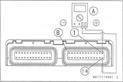
Connect
a digital voltmeter [A] to the connector [B], with
the
needle adapter set.
Special
Tool - Needle Adapter Set: 57001-1457
Atmospheric
Pressure Sensor Input Voltage Connections to ECU Meter (+) -» BL
lead (terminal 1)
Meter
(-) -> BR/BK lead (terminal 14)
Measure
the input voltage with the engine stopped, and with the connectors
joined.
Turn
the ignition switch ON.
Standard: 4.75
- 5.25 V DC
If
the reading of input voltage is less than the standard range, check
the ECU for its ground, and power supply (see this chapter). If the
ground and power supply are good, replace the ECU.
http://moto.amoti.rtt/
Input Voltage at ecu
FUEL
SYSTEM (DFI) 3-83
Atmospheric
Pressure Sensor (Service Code 15)
If
the reading is within the standard range, remove the
seat
cover, and check the input voltage again at the sen-
sor
connector.
Remove
the air cleaner housing (see Air Cleaner Housing
Removal).
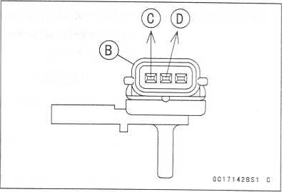
Disconnect
the atmospheric pressure sensor connector
and
connect the harness adapter [A] between the main
harness
connector and pressure sensor connector.
Connect
a digital meter to the harness adapter leads.
[B]
Atmospheric Pressure Sensor
Special
Tool - Throttle Sensor Harness Adapter #2:
57001-1408
Atmospheric
Pressure Sensor Input Voltage
Connections
to Sensor
Meter
(+) -> BL lead [C]
Meter
(-) -> BR/BK lead [D]
Measure
the input voltage with the engine stopped, and
with
the connector joined.
Turn
the ignition switch ON.
If
the reading is out of the standard range, check the wiring (see
wiring diagram in this section).
If
the reading is good, the input voltage is normal. Check the output
voltage.
Turn
the ignition switch OFF.
http://moto.amoti.rtt/
Input Voltage at Sensor Connector Standard: 4.75 - 5.25 V dc

3-84
FUEL SYSTEM (DFI)
Atmospheric
Pressure Sensor (Service Code 15)
Output
Voltage Inspection
Measure
the output voltage at the ECU in the same way
as
input voltage inspection. Note the following.
Digital
Meter [A]
ECU
Connector [B]
Atmospheric
Pressure Sensor Output Voltage
Connections
to ECU
Meter
(+) G/W lead (terminal 4)
Meter
(-) -» BR/BK lead (terminal 14)
Output
Voltage
Usable
Range: 3.80 - 4.20 V DC at the standard
atmospheric
pressure (101.32 kPa, 76
cmHg
abs.)
NOTE
O
The
output voltage changes according to the local at-
mospheric
pressure.
O
The
atmospheric sensor output voltage is based on
a
nearly perfect vacuum in the small chamber of the
sensor.
So, the sensor indicates absolute atmospheric
pressure.
If
the output voltage is within the usable range, check the
ECU
for its ground, and power supply (see this chapter). If
the
ground and power supply are good, replace the ECU.
If
the output voltage is far out of the usable range, remove
the
fuel tank, and check the output voltage at the sensor
connector
[A] (when the wiring is open, the output voltage
is
about 1.8 V).
Connect
a digital meter [A] to the harness adapter leads.
[B]
Atmospheric Pressure Sensor
Special
Tool - Throttle Sensor Harness Adapter #2:
57001-1408
Atmospheric
Pressure Sensor Output Voltage
Connections
to Sensor
Meter
(+) -» G/W lead [C]
Meter
(-) -» BR/BK lead [D]
Output
Voltage at Sensor
Usable
Range: 3.80 - 4.20 V DC at the standard
atmospheric
pressure (101.32 kPa, 76
cmHg
abs)
If
the output voltage is normal, check the wiring for conti-
nuity
(see next diagram).
If
the output voltage is out of the usable range, replace
the
sensor.
http://moto.amoti.rtt/

FUEL
SYSTEM (DFI) 3-85
Atmospheric
Pressure Sensor (Service Code 15)
©
cvjr-ocncor^(om'cnc\’-oocoi—
coiotj-cocm
>Qtf>in^f’T'«TTfTrTrTfTTrf^(»}f?wcoconnwcoocsjCNi
csjcsi cgcsicvjcNicvjcsj^ — - — —
— ^-^-^-cnoor^<£5Ln',TrnCsJ’'
©
jlrbk
1.
ECU
2.
Atmospheric Pressure Sensor
6C17105B«2
C
If
you need to check the atmospheric pressure sensor for various
altitudes other than sea level, check the output voltage as
follows:
O
Determine the local altitude (elevation). ★
★ If
you know the local atmospheric pressure using a barometer,
substitute the atmospheric pressure for throttle vacuum
pressure in the inlet air pressure sensor chart (see intake Air
Pressure Sensor section in this chapter). And get the usable range
of the atmospheric pressure sensor output voltage and check if
output voltage is within the standard or not in the same way as
Output Voltage Inspection of the inlet air pressure sensor.i
i i i i i r i i i i i m
i
i ri
i
i i i i i m
i
i i i m
i i m
i i i i i i i i i i i i i m
r
If you know the local altitude, use the following chart.
http://moto.amoti.rtt/
G/W
3-86
FUEL SYSTEM (DFI)
Atmospheric
Pressure Sensor (Service Code 15)
Atmospheric
Pressure/Altitude Relationship
http://moto.amoti.rtt/
FUEL
SYSTEM (DFI) 3-87
Crankshaft
Sensor (Service Code 21)
Start
the engine and switch the diagnosis mode to Dealer 1 mode to know
all the problem that the DFI system has at the time of
self-diagnosis. If the engine cannot be started, the self-diagnosis
system does not detect dynamic condition of the crankshaft
sensor. In this case turn off the ignition switch and turn it
on again to enter the Dealer 2 mode. In this mode the system tells
all the troubles which the DFI system had in both static and dynamic
conditions.
Crankshaft
Sensor Removal/lnstallation
See
the Ignition System section in the Electrical System chapter.
Crankshaft
Sensor Inspection
OThe
crankshaft have no power source, and when the engine stops, the
crankshaft generates no signals.
Crank
the engine and measure the peak voltage of the crankshaft sensor
(see Electrical System chapter) in order to check the sensor.
Check
the wiring for continuity, using the following diagram.
http://moto.amoti.ru/

3-88
FUEL SYSTEM (DFI)
Camshaft
Position Sensor (Service Code 23)
Start
the engine and switch the diagnosis mode to Dealer 1 mode to know
all the problem that the DFI system has at the time of
self-diagnosis. If the engine cannot be started, the self-diagnosis
system does not detect dynamic condition of the camshaft
position sensor. In this case turn off the ignition switch and turn
it on again to enter the Dealer 2 mode. In this mode the system
tells all the troubles which the DFI system had in both static and
dynamic conditions.
Camshaft
Position Sensor Removal/lnstallation The
camshaft position sensor detects the position of the camshaft, and
distinguishes the cylinder.
See
the Ignition system section in the Electric System chapter.
Camshaft
Position Sensor Inspection O
The camshaft position sensor have no power source, and when the
engine stops, the camshaft position sensor generates no signal.
Crank
the engine and measure the peak voltage of the camshaft position
sensor (see Electrical System chapter) in order to check the
sensor.
Check
the wiring for continuity, using the following diagram.
©
cm
—
o o> oo
r-co
in
v « w - o
ai co r**
© m ■? n cm
•— ooi
co
r-j|<© uo^s-c-jcm
— oa>cor»(a«vneM
-
©
evil
cm
cmcmcmcmcmcm — — — — — — — — — —
rff
ooor'<oifl^,ncM
—
i
i i i i m
ii i i tt~t i
i i i i i i i i i i m
©
6C17107BV2
C
1.
ECU
2.
Camshaft Position Sensor
http://moto.amoti.ru/
![]()
Speed
Sensor (Service Code 24, 25)
FUEL
SYSTEM (DFI) 3-89
Speed
Sensor Removal/lnstallation •
See the Switches and Sensors section in teh Electrical System
chapter.
Speed
Sensor Inspection
•
See
the Switches and Sensors section in teh Electrical System chapter.
Input Voltage Inspection
NOTE
O Be sure the battery is fully charged.
Turn the ignition switch OFF.
Remove the fuel tank (see Fuel Tank Removal).
Disconnect the speed sensor connector [A] and connect the harness adapter [B] between the harness connector and speed sensor connector.
Connect a digital meter to the harness adapter leads. Special Tool - Throttle Sensor Setting Adapter:
57001-1400
Speed Sensor Input Voltage Connector to Sensor Meter (+) -> P lead [C]
Meter (-) -> BK lead [D]
