
- •Foreword
- •A warning
- •General Information table of contents
- •Before Servicing
- •Before Servicing
- •Before Servicing
- •Model Identification
- •Periodic Maintenance table of contents
- •Special Tools
- •A warning
- •Idle Speed
- •Special Tool - Lead Wire-Peak Voltage Adapter: 57001-1449
- •Caution •
- •Caution
- •If dirt or dust is allowed to pass through into the throttle assy, the throttle may become stuck, possibly causing an accident.
- •If dirt gets through into the engine, excessive engine wear and possibly engine damage will occur.
- •A warning
- •If hard water is used in the system, it causes scales accumulation in the water passages, and considerably reduces the efficiency of the cooling system.
- •Valve Clearance
- •Valve Clearance Adjustment
- •Valve clearance adjustment chart inlet valve
- •A warning
- •A warning
- •Mm (0.15 in.) (michelin) Service Limit: 1 mm (0.04 in.),
- •5.6 Mm (0.22 in.) (michelin) Service Limit: 2 mm (0.08 in.) (Up to 130 km/h)
- •3 Mm (0.12 in.) (Over 130 km/h)
- •A warning
- •A warning
- •A warning
- •A warning
- •Immediately blow the chain dry with compressed air after cleaning.
- •A warning
- •A warning
- •A warning
- •On the insulator, as shown. Other spark plugs will wear prematurely.
- •Fuel System (dfi) table of contents
- •Outline
- •Inquiries to Rider
- •Ignition sw off:
- •Ignition sw on:
- •43 (W) Terminal 12.5 V or more Battery Voltage (12.5 V or more)
- •Inspection Flow Chart
- •A warning
- •A warning
- •A warning
- •A warning
- •A warning
- •A warning
- •Standard- BatterY Voltage (12.5 V or more) for 3 seconds, and then 0 V.
- •Caution
- •Injector Resistance Connections to Injector
- •Idle Speed
- •It has been adjusted and set with precision at the factory.
- •Inlet Air Pressure Sensor Input Voltage Connections to ecu
- •Input Voltage at ecu Standard: 4.75 - 5.25 V dc
- •Inlet Air Pressure Sensor (Service Code 12)
- •Inlet Air Pressure Sensor Output Voltage Connection to Sensor
- •Inlet Air Pressure Sensor (Service Code 12)
- •Inlet Air Temperature Sensor (Service Code 13)
- •Inlet Air Temperature Sensor Resistance Standard: 1.6 - 3.7 kH at 20°c (68°f)
- •Inlet Air Temperature Sensor (Service Code 13)
- •Input Voltage at ecu
- •Input Voltage at Sensor Connector Standard: 4.75 - 5.25 V dc
- •Input Voltage at Sensor
- •Vehicle-down Sensor (Service Code 31)
- •Valve full opening to closing)
- •Input Voltage at ecu
- •Input Voltage at Sensor
- •A warning
- •Caution
- •If dirt gets into the engine, excessive engine wear and possible engine damage will occur. •
- •A warning
- •Air Line
- •A warning
- •A warning
- •In the tank cap. This could cause damage and clogging of the labyrinth in the cap.
- •A warning
- •A warning
- •A warning
- •Cooling System table of contents
- •Special Tool
- •6 Cooling system Coolant Flow Chart
- •If coolant must be added often, or the reservoir tank has run completely dry, there is probably leakage in the cooling system. Check the system for leaks. * •
- •Radiator, Radiator Fan
- •A warning
- •Radiator, Radiator Fan
- •Caution
- •Engine Top End table of contents
- •R marked side face up.
- •Rn marked side face up.
- •A marking hollow facing forward.
- •78.2: Horsepower 78.2 kW (106.3 ps) h: Honeycomb Type Catalyst
- •Caution
- •Caution •
- •Valve Seating Surface Width
- •Caution
- •Top Ring [d] Oil Ring Expander
- •Second Ring [e] Lower Oil Ring Steel Rail
- •Upper Oil Ring Steel Rail [f] Hollow
- •Muffler
- •A warning
- •Install the muffler body and exhaust pipe.
- •Clutch table of contents
- •If new dry friction plates and steel plates are installed, apply engine oil to the surfaces of each plate to avoid clutch plate seizure. * •
- •Engine Lubrication System table of contents
- •Engine Oil Flow Chart
- •A warning
- •A warning
- •A warning
- •Engine Removal/lnstallation table of contents
- •A warning
- •Crankshaft / Transmission table of contents
- •Caution
- •A warning
- •Caution
- •Immediately dry the bolts and nuts with compressed air after cleaning.
- •Table of contents
- •A warning
- •Specia Tools
- •Inside Circlip Pliers : 57001-143
- •A warning
- •Valve Core (let out the air)
- •Inspect the rim and tire, and replace them if necessary.
- •Final Drive table of contents
- •G: Apply grease. Ho: Apply heavy oil.
- •Special Tools
- •Inside Circlip Pliers : Jack :
- •Special Tool * Inside Circlip Pliers: 57001-143 [b]
- •Special Tool - Inside Circlip Pliers: 57001-143
- •If the runout exceeds the service limit, replace the rear sprocket.
- •Brakes table of contents
- •Special Tools
- •Inside Circlip Pliers : 57001-143
- •Caution
- •Caution
- •Immediately wash away any brake fluid that spills. Note
- •Caution
- •Immediately wash away any brake fluid that spills.
- •A warning
- •A warning
- •A warning
- •Isopropyl alcohol, or ethyl alcohol.
- •A warning
- •A warning
- •Immediately wash away any brake fluid that spills. * •
- •18 Brakes Master Cylinder
- •Caution
- •Caution
- •Suspension table of contents
- •Exploded View
- •Special Tools
- •Inside Circlip Pliers : 57001-143
- •(From the top of the outer tube) note
- •If the inner tube is badly bent or creased, replace it. Excessive bending, followed by subsequent straightening, can weaken the inner tube.
- •A warning
- •A warning
- •Caution * ★
- •24 Suspension
- •Steering table of contents
- •4 Steering Special Tools
- •A warning
- •Fairings
- •Insert the projection of rear fender rear under the rear fender front.
- •Install the front part of the flap under the rear fender rear.
- •Install the harness clamp in accordance with Harness Routing section in Appendix chapter.
- •A warning
- •Electrical System table of contents
- •Parts Location
- •Precautions
- •If by chance an excessive amount of gas is generated due to overcharging, the safety valve operates to keep the battery safe.
- •A warning
- •A warning
- •If possible, do not quick charge. If the quick charge is done due to unavoidable circumstances, do standard charge later on.
- •If 24 volts is applied for more than a few seconds, the regulator/rectifier may be damaged.
- •Ignition System
- •Ignition System Troubleshooting
- •Ignition System
- •A warning
- •Ignition System
- •Ignition System
- •Ignition System
- •Ignition Coil Winding Resistance
- •Ignition System
- •A warning
- •If the reading is less than the specified value, check the following.
- •Insert the spark plug vertically into the plug hole with the plug [a] installed in the plug wrench [b],
- •Ignition System
- •Ignition System
- •Ignition System
- •1St Check
- •Interlock Operation Voltage Standard: 4 V or more
- •Ignition System
- •2Nd Check
- •Ignition System
- •Ignition System Circuit
- •Turn Signal Light Circuit
- •A warning
- •Caution
- •Appendix table of contents
- •Ic igniter in ecu trouble Fuel/air mixture incorrect:
Sensor Resistance Inspection
Remove the inlet air temperature sensor (see this section).
Suspend the sensor [A] in a container of machine oil so that the heat-sensitive portion is submerged.
Suspend a thermometer [B] with the heat-sensitive portion [C] located in almost the same depth with the sensor.
NOTE
O The sensor and thermometer must not touch the container side or bottom.
Place the container over a source of heat and gradually raise the temperature of the oil while stirring the oil gently for even temperature.
Using a digital meter, measure the internal resistance of the sensor across the terminals at the temperatures shown in the table.
Inlet Air Temperature Sensor Resistance Standard: 1.6 - 3.7 kH at 20°c (68°f)
0.24 ~ 0.43 kQ at 80°C (176°F)
If the measurement is out of the range, replace the sensor.
If the measurement is within the specified, replace the ECU.
http://moto.amoti.rtt/
3-78
FUEL SYSTEM (DFI)
©
«n
*— ©oioor~*(oir>^rooes4 — ocicor^toin^eoM — ooico r-JIco
inTrcoesi — ooeor'-tom^nc'j — o
csJcm
cm cm cm cm cm cm •
T"
a
o>
co <o in "C-co tM -
II
I I I II I I I I I I I II I I I I I I I I I ITT11
I I I I I I I I I I I I I I I I I
3
SC
1 71038W2 C
1.
ECU
2.
Inlet Air Temperature Sensor
http://moto.amoti.rtt/Inlet Air Temperature Sensor (Service Code 13)
Water
Temperature Sensor (Service Code 14)
FUEL
SYSTEM (DFI) 3-79
Removal/lnstalla
tion
~ CAUTION
Never
drop the sensor, especially on a hard surface. Such a shock to the
sensor can damage it.
•
Disconnect
the sensor connector [A], and unscrew the water temperature sensor
[B],
Silicone Sealant (Kawasaki Bond: 56019-120)
- Threads of Water Temperature Sensor
Torque - Water Temperature Sensor: 25 N m (2.5 kgf-m, 18 ft-lb)
• Fill the engine with coolant and bleed the air from the cooling system (see Coolant Filling in the Cooling System chapter).
Output Voltage Inspection
NOTE
O Be sure the battery is fully charged.
• Remove the ECU (see this chapter). Do not disconnect the connectors.
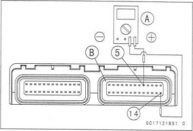
Connect a digital voltmeter [A] to the ECU connector [B], with the needle adapter set.
Special Tool - Needle Adapter Set: 57001-1457
Water Temperature Sensor Output Voltage Connections to ECU Meter (+) -» O lead (terminal 5)
Meter (-) -» BR/BK lead (terminal 14)
Measure the sensor output voltage with the engine stopped and the connector joined.
Turn the ignition switch ON.
Output Voltage at ECU
Standard: about 3 ~ 6 V at 20°C (68CF)
NOTE
O The output voltage changes according to the coolant temperature in the engine.
http://moto.amoti.rtt/
3-80
FUEL SYSTEM (DFI)
Water
Temperature Sensor (Service Code 14)
Turn
the ignition switch OFF.
If
the output voltage is out of the specified, check the ECU for its
ground, and power supply (see this chapter). If the ground and
power supply are good, replace the ECU.
If
the output voltage is far out of the specified (e.g. when the
wiring is open, the voltage is about 5V), check the wiring (see
next diagram).
If
the wiring is good, check the water temperature sensor resistance.
Remove
the needle adapter set, and apply silicone sealant to the seals of
the connector for waterproofing.
Silicone
Sealant (Kawasaki Bond: 56019-120)
-
Seals of ECU Connectors
©
oo)COMCtf)vn!N-00)cor'»invnN"-oo)oo
r'-Jco Lo^rcocsj'—OCTiaa —-to-n^rcocs^* *—o ,
cr>
oo r—■ to io
ro csi *—| cvJo-j —
—————————
)
*
s
m
or
III
©
©
Q
C17104342 C
1.
ECU 2. Meter 3. Water Temperature Sensor
Sensor
Resistance Inspection
Remove
the water temperature sensor (see this section).
• Refer
to Electrical System chapter for water temperature sensor
inspection.
http://moto.amoti.rtt/
FUEL
SYSTEM (DFI) 3-81
Atmospheric
Pressure Sensor (Service Code 15)
CAUTION ~~
Never
drop the sensor, especially on a hard surface.
Such
a shock to the sensor can damage it.
Removal
Turn
the ignition switch off.
Remove:
Air
Cleaner Housing (see Air Cleaner Housing Removal) Atmospheric
Pressure Sensor Connector [A] Atmospheric Pressure Sensor Screw [B]
Atmospheric
Pressure Sensor [C]
GC17B133
F
Installation
NOTE
O
The
atmospheric pressure sensor is the same part as the inlet air
pressure sensor except that the inlet air pressure sensor has a
inlet air pressure hose and different wiring.
Installation
is reverse of removal.
Tighten
the sensor bolts.
Torque
- Atmospheric Pressure Sensor Screw: 4.9 N-m (0.50 kgf-m, 43 in-lb)
http://moto.amoti.ru/