

3-54
FUEL SYSTEM (DFI) Fuel Injectors
Injector
Resistance Inspection
Remove
the throttle body assy (see Throttle Body Assy
Removal).
Disconnect
the connector from the injector [A] (see Throt-
tle
Body Disassembly/Assembly).
Measure
the injector resistance with the hand tester [Bj.
Special
Tool - Kawasaki Hand Tester: 57001-1394
Meter
(+) Meter (-)
#1:
W/R <—> BL/R Terminal
#2:
W/R <—> BL/G Terminal
#3:
W/R <—► BL/BK Terminal
#4:
W/R <—>
BL/Y Terminal
Standard: about
11.7 ~ 12.3 fl
@20°C (68°F)
If
the reading is out of the range, perform the “Injector
Unit
Test”.
If
the reading is normal, perform the “Injector Unit Test”
for
confirmation.
Injector
Unit Test
Use
two leads [A] and the same test light set [B] as in
“Injector
Signal Test”.
Rating
of Bulb [C]: 12 V • * (3 - 3.4) W
12
V Battery [D]
CAUTION
Be
sure to connect the bulb in series. The bulb
works
as a current limiter to protect the solenoid
in
the injector from excessive current.
Connect
the test light set to the injector [E] as shown.
Open
and connect [F] the end of the lead to the battery (-) terminal
repeatedly. The injector should click.
• If
the injector does not click, replace the injector.
Injector Resistance Connections to Injector


http://moto.amoti.ru/
Fuel
Injectors
FUEL
SYSTEM (DFI) 3-55
Injector
Voltage Inspection
Turn
the ignition switch OFF.
Remove:
Fuel
Tank (see Fuel Tank Removal)
Connect
a digital voltmeter [A] to the connector [B], with
the
needle adapter set.
Special
Tool - Needle Adapter Set: 57001-1457
Injector
Power Source Voltage
Connector
to Injector #1, #2, #3, #4
Meter
(+) -> W/R lead
Meter
(-) Battery (-) Terminal
Install
the fuel tank.
Turn
the ignition switch ON.
Power
Source Voltage at Injector Connector
Standard: Battery
Voltage (12.5 V or more)
If
the power source voltage is less than standard, check
the
wiring (see wiring diagram in this section), fuel pump
relay
(Fuel Pump Relay Inspection) and ECU power
source
(see ECU Power Supply Inspection).
Turn
the ignition switch OFF.
Remove:
Fuel
Tank (see Fuel Tank Removal)
Connect
a digital voltmeter [A] to the connector [B], with
the
needle adapter set [Cj.
Special
Tool - Needle Adapter Set: 57001-1457
Injector
Output Voltage
Connections
to Injector #1
Meter
(+) BL/R lead
Meter
(-) -> Battery (-) Terminal
Connections
to Injector #2
Meter
(+) -> BL/G lead
Meter
(-) -» Battery (-) Terminal
Connections
to Injector #3
Meter
(+) -» BL/BK lead
Meter
(-) -» Battery (-) Terminal
Connections
to Injector #4
Meter
(+) -> BL/Y lead
Meter
(-) -» Battery (-) Terminal
Install
the fuel tank.
Turn
the ignition switch ON.
BL/Y
BL/BK BL/G BL/R
Output
Voltage at Injector Connector Standard: Battery Voltage (12.5 V or
more)
★
If
the output voltage is out of the standard, replace the ECU.


http://moto.amoti.rtt/
3-56
FUEL SYSTEM (DFI) Fuel Injectors
Injector
Fuel Line Inspection
Remove
the throttle body assy (see this chapter).
Check
the injector fuel line for leakage as follows:
O
Connect a commercially available vacuum/pressure
pump
[A] to the nipple of the delivery pipe [B] with the
fuel
hose [C] (both ends connected with the clamps [D])
as
shown.
Torque
- Fuel Hose Clamp Screws: 1.5 N-m (0.15 kgf-m, 13
in-lb)
O
Apply soap and water solution to the areas [E] as shown,
o
Watching the pressure gauge, squeeze the pump lever
[F],
and build up the pressure until the pressure reaches
the
maximum pressure.
Fuel
Line Maximum Pressure
Standard: 300
kPa (3.06 kgf/cmJ,
43 psi)
CAUTION
During
pressure testing, do not exceed the maxi-
mum
pressure for which the system is designed.
Watch
the gauge for at least 6 seconds.
If
the pressure holds steady, the system is good.
If
the pressure drops at once, or if bubbles are found in
the
area, the line is leaking. Replace the delivery pipe,
injectors
and related parts.
O
Repeat the leak test, and check the fuel line for no leak-
age.
Install
the throttle body assy (see this chapter).
Run
the hoses correctly (see Cable, Wire, and Hose Rout-
ing
section in Appendix chapter).
http://moto.amoti.ru/

FUEL
SYSTEM (DFI) 3-57
Fuel
Injectors
©
N<-O9>00P
t
“
IQlAVnN^O<7>OOI*'(OinTI,)N^09ICOr
'(OlOVON-O,
III II
I M I I I II IITl 11 I I I I I II I I I I I II I I I I I I I I I I I
I I f
ECU
Fuel
Injector #4
Fuel
Injector #3
Fuel
Injector #2
Fuel
Injector #1
Ignition
Switch
ECU
Main Relay
Fuel
Pump Relay
9.
ECU Fuse 15 A
Main
Fuse 30 A
Starter
Relay
Battery
Engine
Stop Switch
Ignition
Fuse 10 A
Junction
Box
http://moto.amoti.ru/
3-58
FUEL SYSTEM (DFI) Self-Diagnosis
Self-diagnosis
Outline
The
self-diagnosis system has three modes and can be switched to another
mode by grounding the self-diagnosis terminal [A],
User
Mode:
The
ECU notifies the rider of troubles in DFI system and ignition system
by lighting the FI indicator when DFI system and ignition system
parts are faulty, and initiates fail-safe function. In case of
serious troubles ECU stops the injec- tion/ignition/starter motor
operation.
Dealer
Mode 1:
The
FI indicator LED light emits service code(s) to show the problem(s)
which the DFI system and ignition system has at the moment of
diagnosis.
Dealer
Mode 2:
The
FI indicator light LED emits service code(s) to show the problem(s)
which the DFI system and ignition system had in the past.
Self-diagnosis
Procedures
O
When a problem occurs with the DFI system and ignition system, the
DFI indicator LED light [A] goes on.
NOTE
O
Use
a fully charged battery when conducting self-diagnosis. Otherwise,
the LED light blinks very slowly or doesn’t blink.
O
Keep
the self-diagnosis terminal grounded during self -diagnosis, with a
auxiliary lead. •
• Remove
the seats (see Frame chapter) and pull the self -diagnosis terminal
[G].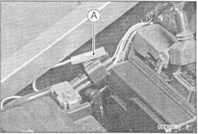

Turn on the ignition switch.
Connect an auxiliary a lead [E] for grounding to the self -diagnosis terminal.
To enter the self-diagnosis dealer mode 1 ground [A] the self-diagnosis indicator terminal to the ground for more than 2 seconds [C], and then keep it grounded continuously [D],
O Count the blinks of the LED light to read the service code. Keep the auxiliary lead ground until you finish reading the service code.

http://moto.amoti.ru/
Self-Diagnosis
FUEL
SYSTEM (DFI) 3-59
•
To
enter the self-diagnosis dealer mode 2 repeat opening [B] and
grounding [A] the lead more than five times [F] within 2 seconds [C]
after the lead is first grounded, and then keep it grounded
continuously [D] for more than 2 seconds.
O Count the blinks of the LED light to read the service code. Keep the auxiliary lead ground until you finish reading the service code.
NOTE
o If the self-diagnosis mode is in dealer mode 1 then you need to enter the dealer mode 2, turn off the ignition switch once.

Service Code Clearing Procedures
Enter the self-diagnosis dealer mode 2 (see Self- diagnosis Procedures).
NOTE
O Make sure to keep the grounding until the following opening and grounding starts.
Pull the clutch lever in more than 5 seconds, and then release it.
• Repeat opening [B] and grounding [A] the lead (self-diagnosis terminal) more than five times [F] within 2 seconds [C] after the lead is grounded, and then keep it grounded continuously [D] for more than 2 seconds.

http://moto.amoti.ru/
Turn the ignition SW (switch) OFF. . i |
|
1 |
|
Turn the ignition SW ON. and self-diagnosis mode starts, using a auxiliary lead. |
|
Dealer |
Dealer |
Dealer
Mode 1.
Grounding
the self-diagnosis indicator terminal for more than 2 seconds and
then keep it grounded.
Dealer
Mode 2.
Repeat
opening and grounding the self-diagnosis indicator terminal more
than five times within 2 seconds after the terminal is first
grounded and then keep it grounded.
FI
indicator LED light blinks to dispaly the fault code for more than 2
seconds.
Locate
the problem with the fault code table and check and repair DFI or
ignition system according to inspection procedure on all fault code.
Remove
the auxiliary lead, ending the self-diagnosis mode.
Make
sure the FI indicator LED light doesn't go ON.
NG
OK
Run
the engine for several minutes at idling and run the motorcycle
at
30 km/h (18 mph) or above in order to confirm no problem.
NG
L
OK
_S__
_
END
http://mofo.amofi.rtt/
FUEL
SYSTEM (DFI) 3-61
Self-Diagnosis
How
to Read Service Codes
O
Service codes are shown by a series of long or short blinks of the
FI indicator LED light as shown below.
o
Read 10th digit and unit digit as the FI indicator LED light blinks.
oWhen
there are a number of problems, all the service codes can be stored
and the display will begin starting from the lowest number service
code in the numerical order. Then after completing all codes, the
display is repeated until the self-diagnosis indicator terminal is
open.
Olf
there is no problem, no code and unlight.
O
For example, if two problems occurred in the order of 21, 12. the
service codes are displayed from the lowest number in the order
listed.
(12
-> 21) -> (12 -» 21) -» • • • (repeated)
sundedr
sn
|
Self-Diagnosis
indicator terminal Groundedp
Open
FI
Indicator LEO Light ON OFF
tittOti
« fit; 0 Ji 9 Si(a digit)
nn
1—TL
1.
Si 0 Si
8CU073B11
C
O
If the problem is with the following parts, the ECU cannot memorize
these problems, the FI indicator LED light doesn’t go on, and no
service codes can be displayed.
FI
Indicator LED Light Fuel Pump Fuel Pump Relay DFI Main Relay
ECU
Power Source Wiring and Ground Wiring (see ECU Inspection in this
chapter)
Fuel
Injectors
How
to Erase Service Codes
O
Even if the ignition SW is turned OFF, the battery or the ECU are
disconnected, or the problem is solved, all service codes remain in
the ECU.
O
Refer to Service Code Clearing Procedure for the service code
erasure.
http://mofo.amofi.ru/
Service Code |
FI Indicator LED Light |
Problems (1) |
||
11 |
jui |
|
Main throttle sensor malfunction, wiring open or short |
|
12 |
rum |
|
Inlet air pressure sensor malfunction, wiring open or short |
|
13 |
JUUlfl |
|
Inlet air temperature sensor malfunction, wiring open or short |
|
14 |
rumjui |
|
Water temperature sensor malfunction, wiring open or short |
|
15 |
rummui |
|
Atmospheric pressure sensor malfunction, wiring open or short |
|
21 |
rrui |
|
Crankshaft sensor malfunction, wiring open or short |
|
23 |
run rum |
|
Camshaft position sensor malfunction, wiring open or short |
|
24 |
rmumrrn |
|
Speed sensor malfunction, wiring open or short |
|
25 |
nrumium |
|
Speed sensor malfunction, wiring open or short |
|
31 |
nnruL |
|
Vehicle-down sensor, malfunction, wiring open or short |
|
32 |
nnrum |
|
Subthrottle sensor malfunction, wiring open or short |
|
51 |
mruiruL |
|
Stick (Ignition) coil #1 malfunction, wiring open or short |
|
52 |
rinrurum |
|
Stick (Ignition) coil #2 malfunction, wiring open or short |
|
53 |
rmunruirm |
|
Stick (Ignition) coil #3 malfunction, wiring open or short |
|
54 |
rrninnrumrm |
|
Stick (Ignition) coil #4 malfunction, wiring open or short |
|
62
|
runruirum |
|
Subthrottle valve actuator malfunction, wiring open or short |
|
Service Codes |
Parts |
Output Signal Usable Range or Criteria |
Backups by ECU |
11 |
Main Throttle Sensor |
Main Throttle Sensor Output Voltage 0.2 -4.8 V ' |
If the main throttle sensor system fails (the signal is out of the usable range, wiring short or open), the ECU locks ignition timing into the ignition timing at closed throttle position and sets the DFI in the D-J method. Also, the main throttle sensor system and inlet air pressure fails, the ECU locks ignition timing into the ignition timing at closed throttle position and sets the DFI in the a-N method. |
12 |
Inlet Air Pressure Sensor |
Inlet Air Pressure (absolute) Pv = 100 mmHg ~ 900 mmHg |
If the inlet air pressure sensor system fails (the signal Pv is out of the usable range, wiring short or open), the ECU sets the DFI in the a - N method (1). |
13 |
Inlet Air Temperature Sensor |
Inlet Air Temperature Ta = - 47CC - + 178=C |
If the inlet air temperature sensor fails (the signal is out of the usable range, wiring short or open), the ECU sets Ta at 40°C. |
14 |
Water Temperature Sensor |
Water Temperature Tw = - 30CC - + 120CC |
If the water temperature sensor system fails (the signal is out of the usable range, wiring short or op en), the ECU sets Tw at 80=C. |
15 |
Atmo spheric Pressure Sensor |
Absolute Atmospheric Pressure Pa = 100 mmHg - 900 mmHg |
If the atmospheric pressure sensor system fails (the signal is out of the usable range, wiring short or open), the ECU sets Pa at 760 mmHg (the standard atmospheric pressure). |
21 |
Crankshaft Sensor |
Crankshaft sensor must send 23 signals (output signal) to the ECU at the one cranking. |
If crankshaft sensor generates less than 23 or more signals, the engine stops by itself. |
23 |
Camshaft Position Sensor |
Cam sensor must send one signal (output signal) to the ECU at the two cranking |
If the camshaft position sensor system fails (the signal is missing, wiring short or open), the ECU continues to ignite cylinders in the same sequence following the last good signal. |
24 |
Speed Sensor |
Speed sensor must send 4 signals (output signal) to the ECU at the one rotation of the engine sprocket |
If the speed sensor system fails (no signal, wiring short or open), the speedometer shows 0. |
25 |
Speed Sensor |
The gear position is decided by the signal of the speed sensor. |
If the speed sensor system fails (no signal, wiring short or open), the ECU set the top (6) gear position. |
Service Codes |
Parts |
Output Signal Usable Range or Criteria |
Backups by ECU |
31 |
Vehicle -down Sensor |
Vehicle-down Sensor Output Voltage (signal) Vd = 0.4 V ~ 4.4 V |
If the vehicle-down sensor system has failures (the output voltage Vd is more than usable range, wiring open), the ECU shuts off the fuel pump, the fuel injectors and the ignition system. |
32 |
Subthrottle sensor |
Subthrottle Sensor Output Voltage 0.15 ~ 4.85 V |
If the subthrottle sensor system fails (the signal is out of the usable range, wiring short or open), the actuator locks sub throttle valve at full open position. |
51 |
Stick Coil #1 (Iqnition Coil)* |
The ignition coil primary winding must send signals (output voltage) continuously to the ECU. |
If the ignition primary winding #1 has failures (no signal, wiring short or open), the ECU shuts off the injector #1 to stop fuel to the cylinder #1, though the engine keeps running. |
52 |
Stick Coil #2 (Ignition Coil)* |
The ignition coil primary winding must send signals (output voltage) continuously to the ECU. |
If the ignition primary winding #2 has failures (no signal, wiring short or open), the ECU shuts off the injector #2 to stop fuel to the cylinder #2, though the engine keeps running. |
53 |
Stick Coil #3 (Ignition Coil)* |
The ignition coil primary winding must send signals (output voltage) continuously to the ECU. |
If the ignition primary winding #3 has failures (no signal, wiring short or open), the ECU shuts off the injector #3 to stop fuel to the cylinder #3, though the engine keeps running. |
54 |
Stick Coil #4 (Iqnition Coil) * |
The ignition coil primary winding must send signals (output voltage) continuously to the ECU. |
If the ignition primary winding #4 has failures (no signal, wiring short or open), the ECU shuts off the injector #4 to stop fuel to the cylinder #4, though the engine keeps running. |
62 |
Subthrottle Valve Actuator |
The actuator operates open and close of the subthrottle valve by the pulse signal from the ECU. |
If the sub throttle actuator fails (the signal is out to the usable range, wiring short or open), the ECU stops the current to the actuator. |
Note:
(1)
a - N Method: the DFI control method from medium to heavy engine
load. When the engine load is light like at idling or low speed, the
ECU determines the injection quantity by calculating from the
throttle vacuum (vacuum sensor output voltage) and engine speed
(crankshaft sensor output voltage). This method is called D-J
method. As the engine speed increases, and the engine load turns
middle to heavy, the ECU determines the injection quantity by
calculating from the throttle opening (throttle sensor output
voltage) and the engine speed. This method is called a - N method.
*
This depends on the number of stopped cylinders.
http://moto.amoti.ru/
Main
Throttle Sensor (Service Code 11)
FUEL
SYSTEM (DFI) 3-65
The
main throttle sensor is a rotating variable resistor that
change
output voltage according to throttle operating. The
ECU
senses this voltage change and determines fuel injec-
tion
quantity, and ignition timing according to engine rpm,
and
throttle opening.
Input
Terminal [A]
Output
Terminal [B]
Ground
Terminal [C]
Main
Throttle Sensor Removal/Adjustment
CAUTION ~
Do
not remove or adjust the main throttle sensor [A]
since
it has been adjusted and set with precision at
the
factory.
Never
drop the sensor, especially on a hard surface.
Such
a shock to the sensor can damage it. *
★
Main
Throttle Sensor Connector [B]
Input
Voltage Inspection
NOTE
O
Be
sure the battery is fully charged.
Turn
the ignition switch OFF.
Remove
the ECU (see this chapter). Do not disconnect the ECU connectors.
Connect
a digital voltmeter [A] to the connector [B], using the needle
adapter set.
Special
Tool - Needle Adapter Set: 57001-1457
Main
Throttle Sensor Input Voltage Connections to ECU Connector Meter
(+)-> BL lead (terminal 1)
Meter
(-)-> BR/BK lead (terminal 4)
Measure
the input voltage with the engine stopped, and with the connectors
joined.
Turn
the ignition switch ON.
Input
Voltage at ECU Connector Standard: 4.75 ~ 5.25 V DC
Turn
the ignition switch OFF.
★ If
the reading of input voltage is less than the standard, check the
ECU for its ground, power supply and wiring shorted.


If the input voltage is within the standard range, check the input voltage at the main throttle sensor connector.
Remove the throttle body assembly temporarily (see Throttle Body Assy Removal).
http://moto.amoti.ru/
3-66
FUEL SYSTEM (DFI)
Main
Throttle Sensor (Service Code 11)
Disconnect
the main throttle sensor connector [A] and
connect
the harness adapter [B] between the harness
connector
and main throttle sensor connector.
Connect
a digital meter to the harness adapter leads.
Special
Tool - Throttle Sensor Harness Adapter : 57001
-1538
Main
Throttle Sensor Input Voltage
Connections
to Sensor
Meter
(+)-> BL lead
Meter
(-)-* BR/BK lead
Install
the throttle body assembly.
Measure
the sensor input voltage with the engine
stopped,
and with the connector joined.
Turn
the ignition switch ON.
Input
Voltage at Sensor Standard: 4.75 ~ 5.25 V DC
Turn
the ignition switch OFF.
If
the reading is out of the range, check the wiring (see wiring
diagram in this section).
If
the reading is good, check the output voltage of the sensor.
http://moto.amoti.rtt/
