
- •Foreword
- •A warning
- •General Information table of contents
- •Before Servicing
- •Before Servicing
- •Before Servicing
- •Model Identification
- •Periodic Maintenance table of contents
- •Special Tools
- •A warning
- •Idle Speed
- •Special Tool - Lead Wire-Peak Voltage Adapter: 57001-1449
- •Caution •
- •Caution
- •If dirt or dust is allowed to pass through into the throttle assy, the throttle may become stuck, possibly causing an accident.
- •If dirt gets through into the engine, excessive engine wear and possibly engine damage will occur.
- •A warning
- •If hard water is used in the system, it causes scales accumulation in the water passages, and considerably reduces the efficiency of the cooling system.
- •Valve Clearance
- •Valve Clearance Adjustment
- •Valve clearance adjustment chart inlet valve
- •A warning
- •A warning
- •Mm (0.15 in.) (michelin) Service Limit: 1 mm (0.04 in.),
- •5.6 Mm (0.22 in.) (michelin) Service Limit: 2 mm (0.08 in.) (Up to 130 km/h)
- •3 Mm (0.12 in.) (Over 130 km/h)
- •A warning
- •A warning
- •A warning
- •A warning
- •Immediately blow the chain dry with compressed air after cleaning.
- •A warning
- •A warning
- •A warning
- •On the insulator, as shown. Other spark plugs will wear prematurely.
- •Fuel System (dfi) table of contents
- •Outline
- •Inquiries to Rider
- •Ignition sw off:
- •Ignition sw on:
- •43 (W) Terminal 12.5 V or more Battery Voltage (12.5 V or more)
- •Inspection Flow Chart
- •A warning
- •A warning
- •A warning
- •A warning
- •A warning
- •A warning
- •Standard- BatterY Voltage (12.5 V or more) for 3 seconds, and then 0 V.
- •Caution
- •Injector Resistance Connections to Injector
- •Idle Speed
- •It has been adjusted and set with precision at the factory.
- •Inlet Air Pressure Sensor Input Voltage Connections to ecu
- •Input Voltage at ecu Standard: 4.75 - 5.25 V dc
- •Inlet Air Pressure Sensor (Service Code 12)
- •Inlet Air Pressure Sensor Output Voltage Connection to Sensor
- •Inlet Air Pressure Sensor (Service Code 12)
- •Inlet Air Temperature Sensor (Service Code 13)
- •Inlet Air Temperature Sensor Resistance Standard: 1.6 - 3.7 kH at 20°c (68°f)
- •Inlet Air Temperature Sensor (Service Code 13)
- •Input Voltage at ecu
- •Input Voltage at Sensor Connector Standard: 4.75 - 5.25 V dc
- •Input Voltage at Sensor
- •Vehicle-down Sensor (Service Code 31)
- •Valve full opening to closing)
- •Input Voltage at ecu
- •Input Voltage at Sensor
- •A warning
- •Caution
- •If dirt gets into the engine, excessive engine wear and possible engine damage will occur. •
- •A warning
- •Air Line
- •A warning
- •A warning
- •In the tank cap. This could cause damage and clogging of the labyrinth in the cap.
- •A warning
- •A warning
- •A warning
- •Cooling System table of contents
- •Special Tool
- •6 Cooling system Coolant Flow Chart
- •If coolant must be added often, or the reservoir tank has run completely dry, there is probably leakage in the cooling system. Check the system for leaks. * •
- •Radiator, Radiator Fan
- •A warning
- •Radiator, Radiator Fan
- •Caution
- •Engine Top End table of contents
- •R marked side face up.
- •Rn marked side face up.
- •A marking hollow facing forward.
- •78.2: Horsepower 78.2 kW (106.3 ps) h: Honeycomb Type Catalyst
- •Caution
- •Caution •
- •Valve Seating Surface Width
- •Caution
- •Top Ring [d] Oil Ring Expander
- •Second Ring [e] Lower Oil Ring Steel Rail
- •Upper Oil Ring Steel Rail [f] Hollow
- •Muffler
- •A warning
- •Install the muffler body and exhaust pipe.
- •Clutch table of contents
- •If new dry friction plates and steel plates are installed, apply engine oil to the surfaces of each plate to avoid clutch plate seizure. * •
- •Engine Lubrication System table of contents
- •Engine Oil Flow Chart
- •A warning
- •A warning
- •A warning
- •Engine Removal/lnstallation table of contents
- •A warning
- •Crankshaft / Transmission table of contents
- •Caution
- •A warning
- •Caution
- •Immediately dry the bolts and nuts with compressed air after cleaning.
- •Table of contents
- •A warning
- •Specia Tools
- •Inside Circlip Pliers : 57001-143
- •A warning
- •Valve Core (let out the air)
- •Inspect the rim and tire, and replace them if necessary.
- •Final Drive table of contents
- •G: Apply grease. Ho: Apply heavy oil.
- •Special Tools
- •Inside Circlip Pliers : Jack :
- •Special Tool * Inside Circlip Pliers: 57001-143 [b]
- •Special Tool - Inside Circlip Pliers: 57001-143
- •If the runout exceeds the service limit, replace the rear sprocket.
- •Brakes table of contents
- •Special Tools
- •Inside Circlip Pliers : 57001-143
- •Caution
- •Caution
- •Immediately wash away any brake fluid that spills. Note
- •Caution
- •Immediately wash away any brake fluid that spills.
- •A warning
- •A warning
- •A warning
- •Isopropyl alcohol, or ethyl alcohol.
- •A warning
- •A warning
- •Immediately wash away any brake fluid that spills. * •
- •18 Brakes Master Cylinder
- •Caution
- •Caution
- •Suspension table of contents
- •Exploded View
- •Special Tools
- •Inside Circlip Pliers : 57001-143
- •(From the top of the outer tube) note
- •If the inner tube is badly bent or creased, replace it. Excessive bending, followed by subsequent straightening, can weaken the inner tube.
- •A warning
- •A warning
- •Caution * ★
- •24 Suspension
- •Steering table of contents
- •4 Steering Special Tools
- •A warning
- •Fairings
- •Insert the projection of rear fender rear under the rear fender front.
- •Install the front part of the flap under the rear fender rear.
- •Install the harness clamp in accordance with Harness Routing section in Appendix chapter.
- •A warning
- •Electrical System table of contents
- •Parts Location
- •Precautions
- •If by chance an excessive amount of gas is generated due to overcharging, the safety valve operates to keep the battery safe.
- •A warning
- •A warning
- •If possible, do not quick charge. If the quick charge is done due to unavoidable circumstances, do standard charge later on.
- •If 24 volts is applied for more than a few seconds, the regulator/rectifier may be damaged.
- •Ignition System
- •Ignition System Troubleshooting
- •Ignition System
- •A warning
- •Ignition System
- •Ignition System
- •Ignition System
- •Ignition Coil Winding Resistance
- •Ignition System
- •A warning
- •If the reading is less than the specified value, check the following.
- •Insert the spark plug vertically into the plug hole with the plug [a] installed in the plug wrench [b],
- •Ignition System
- •Ignition System
- •Ignition System
- •1St Check
- •Interlock Operation Voltage Standard: 4 V or more
- •Ignition System
- •2Nd Check
- •Ignition System
- •Ignition System Circuit
- •Turn Signal Light Circuit
- •A warning
- •Caution
- •Appendix table of contents
- •Ic igniter in ecu trouble Fuel/air mixture incorrect:
Fuel
Line
FUEL
SYSTEM (DFI) 3-47
Open
the fuel tank cap [A] to lower the pressure in the tank.
Be
sure to place a piece of cloth around the fuel supply pipe of the
fuel pump.
Remove
the fuel hose from the fuel pump (see Fuel Pump Removal).
Be
prepared for fuel spillage; any spilled fuel must be completely
wiped up immediately.
When
the fuel hose is disconnected, fuel spills out from the hose and the
pipe because of residual pressure. Cover the hose connection with a
piece of clean cloth to prevent fuel spillage.
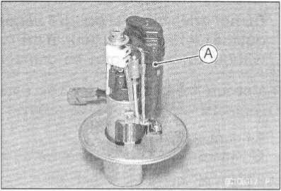
Connect
the prepared fuel hose [A] to the fuel supply pipe of the fuel
pump.
Secure
the fuel hose with a clamp.
Insert
the fuel hose into the measuring cylinder [B],
Wipe
off spilled out fuel immediately.
Be
sure to hold the measuring cylinder vertical.
Close
the fuel tank cap.
With
the engine stopped, turn the ignition switch ON. The fuel pump
should operate for 3 seconds, and then should stop.
CAUTION
Do
not drive the fuel pump 3 seconds or more without the fuel in
the fuel tank. If the fuel pump is driven without the fuel, it may
be damaged. •
Measure
the discharge for 3 seconds.
O
Repeat this operation several times.
Amount
of Fuel Flow
Standard: 67
mL or more for 3 seconds
If
the fuel flow is much less than the specified, check the following:
Battery
Condition (see Electrical System chapter)
• After
inspection, connect the fuel hoses, (see Fuel Tank Installation).A warning
A warning
Start the engine and check for fuel leakage.
http://moto.amoti.ru/
3-48
FUEL SYSTEM (DFI) Fuel Pump
Fuel
Pump Removal
CAUTION
Never
drop the fuel pump, especially on a hard surface. Such a shock
to the pump can damage it.
Gasoline
is extremely flammable and can be explosive under certain
conditions. Make sure the area is well-ventilated and free from any
source of flame or sparks; this includes any appliance with a pilot
light. Do not smoke. Turn the ignition switch OFF. Disconnect the
battery (-) terminal.
To
make fuel spillage minimum, draw the fuel out from the fuel tank
when the engine is cold. Be prepared for fuel spillage; any spilled
fuel must be completely wiped up immediately. •
Draw
the fuel out from the fuel tank with a commercially available
electric pump.
Remove
the fuel tank (see Fuel Tank Removal).
o
Be careful of fuel spillage from the fuel tank since fuel still
remains in the fuel tank and fuel pump. Plug the fuel pipe of the
fuel tank.
Turn
the fuel tank upside down.
Unscrew
the fuel pump bolts [A], and take out the fuel pump assembly [B]
and gasket.
• Discard
the fuel pump gasket.A warning
CAUTION
Do not pull the leads (C) of the fuel pump and fuel reserve switch. If they are pulled, the lead terminals may be damaged.
Fuel Pump Installation
Remove dirt or dust from the fuel pump [A] by lightly applying compressed air.
Replace the fuel pump gasket with a new one.
http://moto.amoti.ru/
Fuel
Pump
FUEL
SYSTEM (DFI) 3-49
Check
that the fuel pump terminal [A] and band [B] are in place.
[C]
Front
Apply
a non-permanent locking agent to the threads of the fuel pump
bolts.
Tighten
the fuel pump bolts to a snug fit following the tightening
sequence shown.
Following
the tightening sequence, tighten the pump bolts to the specified
torque.
Torque
- Fuel Pump Bolts: 9.8 N m (1.0 kgf-m, 87 in-lb)
Tighten
the pump bolts again to check the tightness in the order shown.
Operation
Inspection
NOTE
O
Be
sure the battery is fully charged.
Turn
the ignition switch ON and make sure that the fuel pump operates
(make light sounds) for 3 seconds, and then stops.
Turn
the ignition switch OFF. ■
If
the pump does not work as described above, inspect the operating
voltage.
Operating
Voltage Inspection
NOTE
O
Be
sure the battery is fully charged.
Turn
the ignition switch OFF.
Remove
the fuel tank bolts and lift up the fuel tank. •
• Connect
the hand tester (25 V DC) to the connector [A], with needle adapter
set.
Special Tools - Hand Tester: 57001-1394
Needle Adapter Set: 57001-1457
O Measure the operating voltage with the engine stopped, and with the connector joined.
Turn the ignition switch ON.
oThe tester needle should indicate battery voltage for 3 seconds, and then 0 V.
Pump Operating Voltage at Pump Connections to Pump Connectors Tester (+) -> Y/R Lead
Tester (-) -> BK/W Lead