

Ignition sw off:
Ignition sw on:
between 13 (W/Y) Terminal and Battery (-) Terminal between 43 (W) Terminal and Battery (-) Terminal 13 (W/Y) Terminal 0 V,
43 (W) Terminal 12.5 V or more Battery Voltage (12.5 V or more)

★ If the tester does not read as specified, check the following:
Power Source Wiring (see wiring diagram below)
Main Fuse 30 A (see Electrical System chapter)
ECU Fuse 15 A (see DFI Power Source section)
ECU Main Relay (see DFI Power Source section)
ECU Power Source Circuit

ECU Main Relay 7. Battery
ECU Fuse 15 A
http://moto.amoti.rtt/
3-42
FUEL SYSTEM (DFI) DFI Power Source
ECU
Fuse Removal
Refer
to the Electrical System chapter for the ECU fuse removal.
ECU
Fuse Installation
If
a fuse fails during operation, inspect the DFI system to determine
the cause, and then replace it with a new fuse of proper amperage.
Refer
to the Electrical System chapter for the ECU fuse installation.
ECU
Fuse Inspection
•
Refer
to the Electrical System chapter for the ECU Fuse Inspection.
ECU Main Relay Removal
CAUTION
Never drop the relay, especially on a hard surface. Such a shock to the relay can damage it.
Remove:
Seats (see Frame chapter)
Remove the ECU main relay [A] from the bracket and disconnect the connector.

ECU Main Relay Inspection
Remove the ECU main relay (see above).
Connect the hand tester [A] and one 12 V battery [B] to the relay connector [C] as shown.
Special Tool - Hand Tester: 57001-1394
Relay Coil Terminals [1] and [2]
Relay Switch Terminals [3] and [4]
Testing Relay
Tester range: 1 H range
Criteria: When battery is connected -» 0 f2
When battery is disconnected -> <x PI
If the relay does not work as specified, replace the relay.

http://moto.amoti.ru/
FUEL
SYSTEM (DFI) 3-43
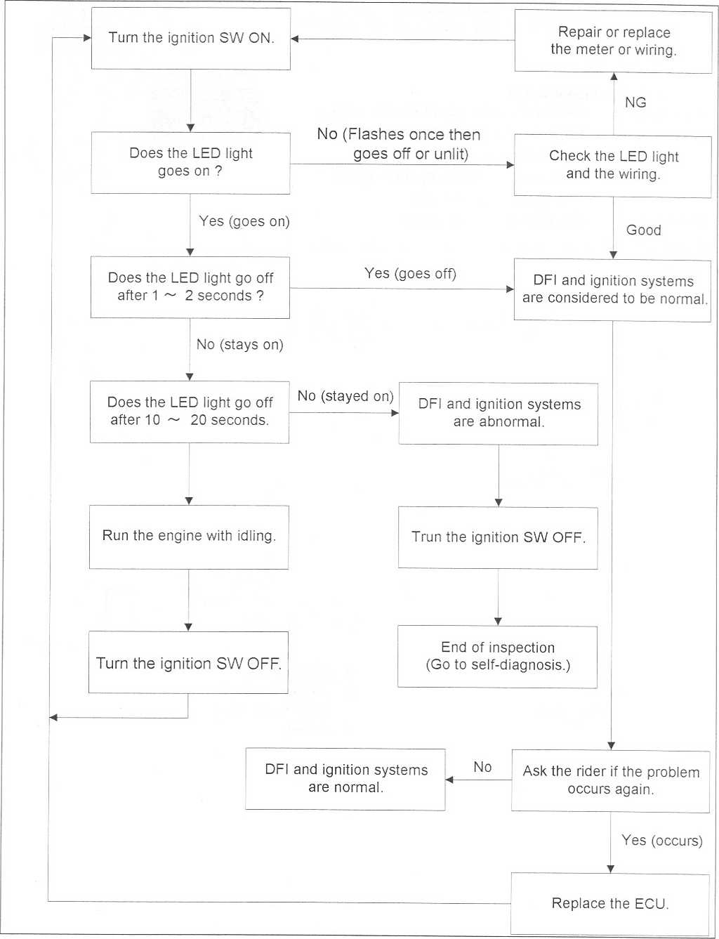
FI
Indicator LED Light
http://moto.amoti.rtt/Inspection Flow Chart
|
ON |
|
|
ill T131 |
Q=! |
i |
|
3 ‘ * i E R Y |
|
|
2=3 |
31 '131 |
cre |
|
|
TAIL! |
|
|
|
T A 1 L 2 |
0=3 |
|
2=3 |
G
C1 709 5912
C |
ECU |
5. |
Ignition Fuse 10 A |
2. |
Ignition Switch |
6. |
Starter Relay |
3. |
FI Indicator LED Light |
7. |
Main Fuse 30 A |
4. |
Junction Box |
8. |
Battery |

http://moto.amoti.rtt/