

3-22
FUEL SYSTEM (DFI) Troubleshooting the DFI System
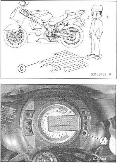
When
an abnormality in the system occurs, the FI indicator LED
(Light Emitting Diode) light goes on to alert the rider on the meter
panel. In addition, the condition of the problem is stored in the
memory of the ECU (electronic control unit). With the engine stopped
and turned in the self-diagnosis mode, the service code [A] is
indicated by the number of times the FI indicator LED light blinks.
When
due to a malfunction, the FI indicator LED light remains lit,
ask the rider about the conditions [B] under which the problem
occurred and try to determine the cause [C], Don’t rely solely on
the DFI self-diagnosis function, use common sense; first conduct a
pre-diagnosis inspection, check the ECU for ground and power supply,
the fuel line for no fuel leaks, and for correct pressure. The
pre-diagnosis items are not indicated by the FI indicator LED light.
Even
when the DFI system is operating normally, the FI indicator LED
light [A] may light up under strong electrical interference. No
remedy needed. Turn the ignition SW (switch) OFF to stop the
indicator light.
When
the FI indicator LED light goes on and the motorcycle is
brought in for repair, check the service codes.
When
the repair has been done, the LED light doesn’t go on. But the
service codes stored in memory are not erased to preserve the
problem history, and the LED light can display the codes in the
self-diagnosis mode. The problem history is referred when solving
unstable problems.
Much
of the DFI system troubleshooting work consists of confirming
continuity of the wiring. The DFI parts are assembled and adjusted
with precision, and it is impossible to disassemble or repair them.
•
•
When
checking the DFI parts, use a digital meter which can be read two
decimal place voltage or resistance.Outline

O Remove:
Seats (see Frame chapter)
oThe DFI part connectors have seals, including the ECU. When measuring the input or output voltage with the connector joined, use the needle adapter set. Insert the needle adapter inside the seal until the needle adapter reaches the terminal (for example, ECU is shown.).
Digital Meter [A]

Special Tool - Needle Adapter Set: 57001-1457
CAUTION
Tape the leads to prevent short circuit of the leads.
htfp77moto.amoti.ru/
Troubleshooting
the DFI System
FUEL
SYSTEM (DFI) 3-23
O
After measurement, remove the needle adapters and apply
silicone sealant to the seals [A] of the connector [B] for
waterproofing.
Silicone
Sealant (Kawasaki Bond: 56019-120)
Seals
of Connector
Always
check battery condition before replacing the DFI parts. A fully
charged battery is a must for conducting accurate tests of the DFI
system.
Trouble
may involve one or in some cases all items. Never replace a
defective part without determining what CAUSED the problem. If the
problem was caused by some other item or items, they too must be
repaired or replaced, or the new replacement part will soon fail
again
Measure
coil winding resistance when the DFI part is cold (at room
temperature)
Do
not adjust or remove the throttle sensor.
Do
not directly connect a 12 V battery to a fuel injector. Insert a
resistor (5 ~ 7 Cl
) or a bulb (12 V x 3 ~ 3.4 W) in series between the battery and
the injector.
The
DFI parts have been adjusted and set with precision. Therefore,
they should be handled carefully, never strike sharply, as with a
hammer, or allowed to drop on a hard surface. Such a shock to the
parts can damage them.
Check
wiring and connections from the ECU connector to the suspected
faulty DFI parts, using the hand tester (special tool, analog
tester) rather than a digital tester. Special
Tool - Hand Tester: 57001-1394
Make
sure all connectors in the circuit are clean and tight, and examine
wires for signs of burning, fraying, etc. Deteriorated leads
and bad connections can cause reappearance of problems and
unstable operation of the DFI system.
If
any wiring is deteriorated, replace the wiring.
http://moto.amoti.rtt/
3-24
FUEL SYSTEM (DFI) Troubleshooting the DFI System
Pull
each connector [A] apart and inspect it for corrosion, dirt, and
damage.
If
the connector is corroded or dirty, clean it carefully. If it is
damaged, replace it. Connect the connectors securely.
Check
the wiring for continuity.
O
Use the wiring diagram to find the ends of the lead which is
suspected of being a problem.
o
Connect the hand tester between the ends of the leads.
oSet
the tester to the * 1 ft
range, and read the tester.
If
the tester does not read 0 Q,
the lead is defective. Replace the lead or the main harness or
the sub harness.
O
If both ends of a harness [A] are far apart, ground [B] the one end
[C], using a jumper lead [D] and check the continuity between
the end [E] and the ground [F], This enables to check a long
harness for continuity. If the harness is open, repair or replace
the harness.
★ Narrow
down suspicious locations by repeating the continuity tests
from the ECU connectors.


If no abnormality is found in the wiring or connectors, the DFI parts are the next likely suspects. Check the part, starting with input and output voltages. However, there is no way to check the ECU itself.
If an abnormality is found, replace the affected DFI part.
If no abnormality is found in the wiring, connectors, and DFI parts, replace the ECU.
o The diagnosis flow chart illustrates the above procedures.
o After inspection, be sure to connect all the DFI electrical connectors. Do not turn the ignition SW ON while the DFI electrical connectors and ignition system connectors are disconnected. Otherwise, the ECU memorizes service codes as open circuit.
http://moto.amoti.rtt/
Troubleshooting
the DFI System
FUEL
SYSTEM (DFI) 3-25
O
Lead Color Codes:
BK:
Black G: Green P: Pink
BL:
Blue GY: Gray PU: Purple
BR:
Brown LB: Light blue R: Red
CH:
Chocolate LG: Light green W: White
DG:
Dark green O: Orange Y: Yellow
o
Electrical Connectors: Female Connectors [A]
Male
Connectors [B]
http://moto.amoti.rtt/

Confirm problems [2], |
Reference items |
|
T |
I |
|
Gather information from rider. |
4- ] Diagnosis sheet |
|
|
|
|
Conduct
pre-diagnosis inspection [3],
▼
Conduct
self-diagnosis inspection [4], 4
Judge
which parts or circuit is faulty.
Pick
up check items [5],
Check
by hand tester and judge harness,
or
connector condition. |
|||
1 |
NG r |
OK E |
|
Replace parts. |
|||
i |
i i |
||
OK Check operation [6], |
|||
|
NG |
||
Replace
ECU.
NG
Check
operation [6],
t
OK
End
of inspection
Self-diagnosis
Fault code table
Problem
chart
DFI
parts location
Diagnosis
sheet
Fault
inspection 11 — 62
DFI
wiring diagram
http://mofo.amofi.ru/
Troubleshooting
the DFI System
FUEL
SYSTEM (DFI) 3-27
Notes:
OK:
No problem.
NG:
Problem exists.
Inspection
starts.
An
abnormality occurs in the DFI system, and the FI indicator LED
light goes on to alert the rider.
Bring
the motorcycle into the shop.
Confirm
problems.
Reproduce
the problems if possible.
Conduct
pre-diagnosis inspection.
The
pre-diagnosis inspection items are not handled by self-diagnosis.
Check the problem before self-diagnosis, considering the symptoms
of the problem.
Pre-diagnosis
Inspection Items
ECU
Power Supply Inspection
ECU
Fuse Inspection
ECU
Main Relay Inspection
FI
Indicator LED Light Operation Inspection
Fuel
Pressure Inspection
Fuel
Flow Rate Inspection
Fuel
Line Leakage Inspection
Fuel
Injectors and Fuel Pump Leakage Inspection
Conduct
self-diagnosis.
Enter
the self-diagnosis mode and count the blinks of the FI indicator
LED light to read the service code.
Check
items.
Decide
the faulty part, referring to the problem chart.
Decide
the check procedure for each faulty part, referring to each section
(Fault Inspection 11 ~ 62).
Operation
check.
Make
sure the FI indicator LED light goes off.
If
the problem is related to startability or idle stability, idle the
engine to confirm that the DFI system and the ignition system are
operating correctly.
If
the problem is related to driveability, ride the motorcycle at 30
km/h (18 mph) or above to confirm that the DFI system and the
ignition system are operating correctly.
http://moto.amoti.rtt/
