
- •1. Основные понятия и положения 11
- •2. Центральное растяжение и сжатие стержня 17
- •3. Геометрические характеристики плоских сечений 42
- •4. Кручение 49
- •5. Изгиб стержней 57
- •Introduction 173
- •1. Basic concepts and principles 175
- •2. Tension and compression of a bar 181
- •3. Geometric characteristics of cross sections 202
- •4. Torsion 208
- •5. Bending of bars 216
- •Index 405 введение
- •1. Основные понятия и положения
- •1.1. Задачи сопротивления материалов, основные гипотезы и допущения
- •1.2. Типы нагрузок и деформаций
- •1.3. Определение внутренних усилий методом сечений. Напряжения
- •2. Центральное растяжение и сжатие стержня
- •2.1. Напряжения и продольная деформация при растяжении и сжатии
- •2.2. Закон Гука при растяжении и сжатии
- •2.3. Поперечная деформация при растяжении и сжатии
- •2.4. Диаграмма растяжения низкоуглеродистой стали
- •2.5. Потенциальная энергия деформации при растяжении
- •2.6. Расчеты на прочность при растяжении и сжатии
- •2.7. Статически неопределимые задачи
- •2.8. Напряжения в наклонных сечениях при растяжении (сжатии) в одном направлении
- •2.9. Закон парности касательных напряжений
- •2.10. Определение напряжений в наклонных сечениях при растяжении (сжатии) в двух направлениях
- •2.11. Определение главных напряжений и положения главных площадок
- •2.12. Зависимость между деформациями и напряжениями при плоском и объемном напряженных состояниях (обобщенный закон Гука)
- •2.13. Работа внешних и внутренних сил при растяжении (сжатии). Потенциальная энергия деформации
- •3. Геометрические характеристики плоских сечений
- •3.1. Статический момент площади
- •3.2. Полярный момент инерции
- •3.3. Осевой момент инерции
- •3.4. Момент инерции при параллельном переносе осей
- •3.5. Главные оси и главные моменты инерции
- •4. Кручение
- •4.1. Определение крутящего момента
- •4.2. Определение напряжений в стержнях круглого сечения
- •4.3. Деформации и перемещения при кручении валов
- •4.4. Потенциальная энергия при кручении
- •5. Изгиб стержней
- •5.1. Типы опор балок
- •5.2. Определение опорных реакций
- •5.3. Определение внутренних усилий при изгибе
- •5.4. Правило знаков для изгибающих моментов и поперечных сил
- •5.5. Дифференциальные зависимости при изгибе
- •5.6. Построение эпюр изгибающих моментов и поперечных сил
- •5.7. Определение нормальных напряжений
- •5.8. Условия прочности по нормальным напряжениям
- •5.9. Потенциальная энергия деформации при изгибе
- •5.10. Теорема о взаимности работ. Теорема о взаимности перемещений
- •5.11. Определение перемещений методом Мора
- •6. Теории прочности
- •6.1. Назначение гипотез прочности
- •6.2. Первая гипотеза прочности
- •6.3. Вторая и третья гипотезы прочности
- •6.4. Энергетические гипотезы прочности
- •7. Сложное сопротивление
- •7.1. Изгиб в двух плоскостях (косой изгиб)
- •7.2. Изгиб с растяжением (сжатием)
- •7.3. Внецентренное сжатие (растяжение)
- •7.4. Кручение с изгибом
- •7.5. Кручение с растяжением (сжатием)
- •7.6. Пример расчета вала на изгиб с кручением
- •8. Расчет тонкостенных сосудов
- •9. Расчет сжатых стержней на устойчивость (продольный изгиб)
- •9.1. Устойчивые и неустойчивые формы равновесия
- •9.2. Формула Эйлера для критической силы
- •9.3. Влияние способа закрепления концов стержня на критическую силу
- •9.4. Пределы применимости формулы Эйлера
- •9.5. Эмпирические формулы для определения критических напряжений
- •9.6. Практическая формула для расчета на устойчивость
- •10. Динамическое действие нагрузок
- •10.1. Динамические нагрузки
- •10.2. Вычисление напряжений при равноускоренном движении
- •10.3. Определение перемещений и напряжений при ударе
- •11. Расчет на прочность при напряжениях, циклически изменяющихся во времени (расчет на усталость)
- •11.1. Основные определения
- •11.2. Кривая усталости при симметричном цикле. Предел выносливости
- •11.3. Диаграммы предельных напряжений и амплитуд цикла
- •11.4. Факторы, влияющие на предел выносливости
- •11.5. Определение коэффициента запаса прочности при симметричном цикле
- •11.6. Определение коэффициента запаса прочности при асимметричном цикле напряжений
- •Предположим, что при увеличении нагрузки на деталь отношение Такое нагружение называется простым.
- •11.7. Практические меры повышения сопротивления усталости
- •Практикум Лабораторная работа № 1
- •Введение
- •Установка
- •Порядок выполнения
- •Контрольные вопросы
- •Литература
- •Лабораторная работа № 2
- •Введение
- •Установка
- •Порядок выполнения
- •Контрольные вопросы
- •Литература
- •Лабораторная работа № 3
- •Введение
- •Установка
- •Порядок выполнения
- •Introduction
- •Basic concepts and principles
- •Tasks, main hypothesis and assumptions of the strength of materials
- •1.2. Types of loads and deformations
- •1.3. Determining the internal forces by the method of sections. Stresses
- •2. Tension and compression of a bar
- •2.1. Stresses and a longitudinal deformation in tension and compression
- •2.2. Hooke,s law in tension and compression
- •2.3. The transverse deformation in tension and compression
- •2.4. The tension diagram of the lowcarbon steel
- •2.5. The potential deformation energy in tension
- •2.6. Strength calculation in tension and compression
- •2.7. Statically indeterminate problems
- •2.8. Stresses at inclined sections under tension (compression) in one direction
- •2.9. Law of the shearing stresses couple
- •2.10. Determination of stresses at the inclined sections in tension (compression) in two directions
- •2.11. Determining the principal stresses and the principal planes position
- •2.12. The relation between the deformations and the stresses for the plane and general stresses (a general form of Hook’s law)
- •2.13. The work of the external and internal forces in tension (compression). Strain energy
- •3. Geometric characteristics of cross sections
- •3.1. First moment of an area
- •3.2. Polar moment of inertia
- •3.3. Axial moment of inertia
- •3.4. The moment of inertia at parallel displacement of axis
- •3.5. Principal axes and principal moment of inertia
- •4. Torsion
- •4.1. Determining the twisting moment
- •4.2. Determining the stresses in the round section bar
- •4.3. The deformations and displacements in the shaft torsion
- •4.4. Internal strain energy in torsion
- •5. Bending of bars
- •5.1. Types of the beam support
- •5.2. Determining the support reactions
- •5.3. Determining the internal stresses in bending
- •5.4. The sign rule for the bending moments and the shearing forces
- •5.5. The differential relationships in bending
- •I.E. The intensity of the distributed load is equal to the derivative of the shearing force with respect to the bar section abscissa.
- •I.E. The shearing force is equal to the derivative of the bending moment with respect to the bar section abscissa.
- •I.E. The second derivative of the bending moment with respect to the bar section abscissa is equal to the intensity of the distributed load.
- •5.6. Drawing bending moment and shearing force diagrams
- •5.7. Determining the normal stress
- •5.8. Strength conditions with normal stresses
- •5.9. Strain energy in bending
- •5.10. Betty’s reciprocal theorem. Reciprocal displacement theorem
- •5.11. Determining displacements by Mohr’s method
- •6. Strengtn theory
- •6.1. The purpose of strength hypotheses
- •6.2. The first strength hypothesis
- •6.3. The second and third strength hypotheses
- •6.4. The energy hypotheses of strength
- •7. Combined stress
- •7.1. Bending in two planes (non-uniplanar bending)
- •7.2. Combined axial tension (compression) and bending
- •7.3. Eceentrical tension (compression)
- •7.4. Combined torsion and bending
- •7.5. Combined torsion and compression
- •7.6. Example of the shaft calculation in bending with torsion
- •8. Calculation of the thin-walled vessels
- •9. Stability analysis of the bars in compression (buckling)
- •9.1. Stable and unstable equilibrium forms
- •9.2. Euler’s formula for the critical force
- •9.3. Influence of bar end conditions on the critical force
- •9.4. Applicability limits of of Euler’s formula
- •9.5. Empirical formula for determining the critical stresses
- •9.6. The practical formula for the stability analysis
- •10. Dynamic load action
- •10.1. Dynamic load
- •10.2. Calculating stresses under the uniformly accelerated motion
- •10.3. Determining displacements and stresses under the impact
- •11. Stress analysis under the stresses changing cyclically in time
- •11.1. Basic definitions
- •11.2. Fatigue (Wohler’s) curve under the symmetrical cycle. Fatigue strength
- •11.3. The limit stress diagram and the cycle amplitude
- •11.4. Factors influencing on the fatigue strength
- •11.5. Determining the factor of safety under the symmetrical cycle
- •11.6. Determining the factor of safety under the asymmetrical stress cycle
- •11.7. Practical measures to increase the fatigue strength
- •Practicum Laboratory work № 1
- •Introduction
- •Installation
- •Test specimens
- •Test questions
- •Literature
- •Laboratory work № 2
- •Introduction
- •Installation
- •Test questions
- •Literature
- •Laboratory work № 3
- •Introduction
- •Installation
- •Individual task report
- •Test questions
- •Literature
- •Англо-русский терминологический словарь
- •Список фамилий ученых
- •Greek alphabet
- •Сокращения
- •Единицы измерения
- •Список наиболее употребительных знаков
- •Список использованной литературы
- •Алфавитный указатель
- •Сопротивление материалов
- •625000, Тюмень, ул. Володарского, 38.
- •625039, Г. Тюмень, ул. Киевская, 52
Installation
An installation for testing elastic buckling of a pin-ended bar is shown in Fig.4.
Bar 1 loading is realized by the lever 6 allowing to decrease load values. Lever 6 runs through the slot in the frame upright and rests on the prism providing a pin joint. The weight of the long lever 6 with the load bracket 7 is balanced by the counterweight 5. The lower bar end 1 is rested on sole 2, the upper end is fixed in slider 3, which is freely sliding, relative to frame 4 along the director, vertically. The pin-ended bar is ensured by this construction.
The installation functions in the following way.
Fig.4.
Installation for testing the bar elastic buckling
Fig.4.
The
loads installed on bracket 7 by lever 6 compress the bar 1. Indicator
9 will show the value of the deflection
under any load due to the initial deflection and a centrical force
action. The value of the compressive force is determined by the lever
rule:
where
is the load weight installed on bracket 7;
is
the bracket weight 7, lever 6, counterweight 5 and slider 3;
a, b are the lever arms (Fig.4).
Testing specimen
Testing bar 1 with a rectangular cross-section is shown in Fig.5. The bar ends are sharpened to ensure a free turn of the butt-end section.
Fig.5. Testing specimen
Order
Make the following operations to determine the critical force using Southwell’s method:
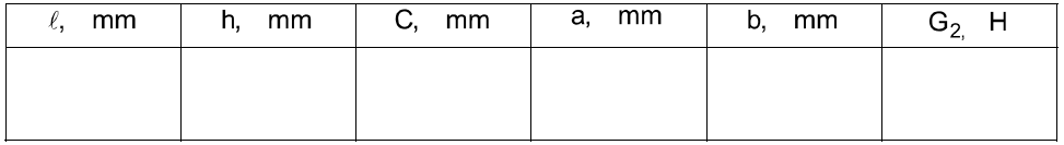
1. Measure the length and the dimensions of the bar section h and c. Make three measurements and write down the average values in table № 1.
2. Set up the bar in the installation.
3. Balance the system by couterweight 5 so that lever 6 was in a horizontal position.
4. Measure the lever arms a and b, then put them in table 1.
5. Measure the weight G2 of bracket 7, lever 6, counterweight 5 and slider 3, write these down in table 1 (for the given installation G2 is equal to 48 N)
Table 1
5. Set the indicator hand to "O".
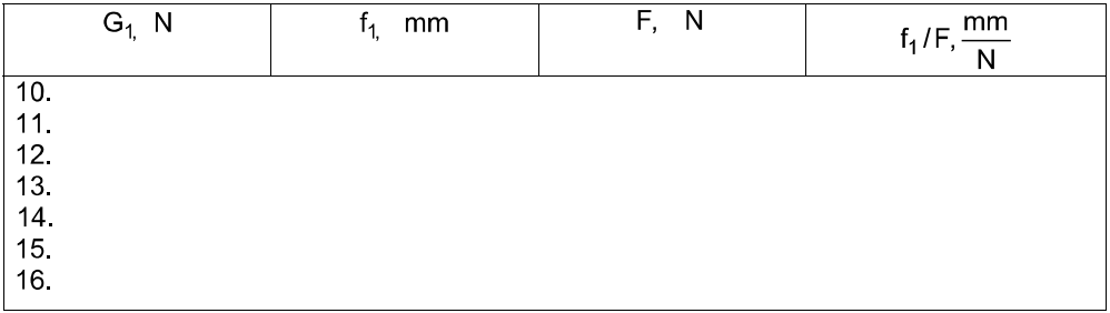
6. Place the weight G1=10H on bracket 7, take the indicator f1 readings and write down these in table 2 for each level.
7. Carry out the stepped loading in 1 N (100gr), take the reading of the indicator f1 to fix in table 2 for each level.
Table 2
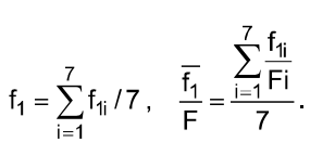
9. By the results of the experiment carry out the following:
9.1. Fill in table 2 using the formula (13) and table 1.
9.2. Calculate
the value
using
table 1 and the formula (2) with E=210 G Pa and
=2,
then put them in table 3.
9.3. Draw a plot (see Fig.3) with table 2 data. Draw a straight line so, that as many experimental points as possible, be near it.
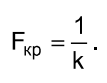
9.4. Determine
the critical force
using the formula (12) and put it in table 3.
9.5. Determine the critical force using the method of least squares, [3]. Let us write the equation (8) in conformity with (9), (10), (11)
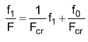
or
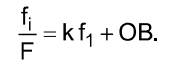
That is the straight line equation (see Fig.3). From the experiment (Table 2) we have some equations
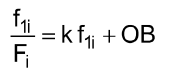
where i =1,2...7 corresponds to each load case G1.
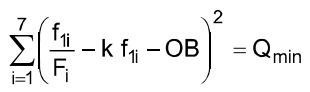
The values k and OB are occasional and they will be the most probable (the straight line will be the best), if the sum of the difference squares is minimum
or from the condition
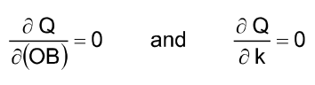
we determine k and OB. After transforming we get
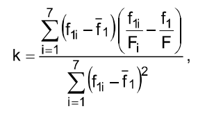
where
The critical force is
Carry out the calculation and put it in table 3.
9.6. Determine the percent divergence in formula (14) and put in table 3
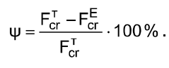
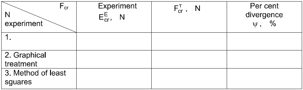
Table 3
Report
The report must include:
1. The title page.
2. The goal of the work.
3. The description of the installation.
4. The test results.
5. Test questions answered.