
- •1. Основные понятия и положения 11
- •2. Центральное растяжение и сжатие стержня 17
- •3. Геометрические характеристики плоских сечений 42
- •4. Кручение 49
- •5. Изгиб стержней 57
- •Introduction 173
- •1. Basic concepts and principles 175
- •2. Tension and compression of a bar 181
- •3. Geometric characteristics of cross sections 202
- •4. Torsion 208
- •5. Bending of bars 216
- •Index 405 введение
- •1. Основные понятия и положения
- •1.1. Задачи сопротивления материалов, основные гипотезы и допущения
- •1.2. Типы нагрузок и деформаций
- •1.3. Определение внутренних усилий методом сечений. Напряжения
- •2. Центральное растяжение и сжатие стержня
- •2.1. Напряжения и продольная деформация при растяжении и сжатии
- •2.2. Закон Гука при растяжении и сжатии
- •2.3. Поперечная деформация при растяжении и сжатии
- •2.4. Диаграмма растяжения низкоуглеродистой стали
- •2.5. Потенциальная энергия деформации при растяжении
- •2.6. Расчеты на прочность при растяжении и сжатии
- •2.7. Статически неопределимые задачи
- •2.8. Напряжения в наклонных сечениях при растяжении (сжатии) в одном направлении
- •2.9. Закон парности касательных напряжений
- •2.10. Определение напряжений в наклонных сечениях при растяжении (сжатии) в двух направлениях
- •2.11. Определение главных напряжений и положения главных площадок
- •2.12. Зависимость между деформациями и напряжениями при плоском и объемном напряженных состояниях (обобщенный закон Гука)
- •2.13. Работа внешних и внутренних сил при растяжении (сжатии). Потенциальная энергия деформации
- •3. Геометрические характеристики плоских сечений
- •3.1. Статический момент площади
- •3.2. Полярный момент инерции
- •3.3. Осевой момент инерции
- •3.4. Момент инерции при параллельном переносе осей
- •3.5. Главные оси и главные моменты инерции
- •4. Кручение
- •4.1. Определение крутящего момента
- •4.2. Определение напряжений в стержнях круглого сечения
- •4.3. Деформации и перемещения при кручении валов
- •4.4. Потенциальная энергия при кручении
- •5. Изгиб стержней
- •5.1. Типы опор балок
- •5.2. Определение опорных реакций
- •5.3. Определение внутренних усилий при изгибе
- •5.4. Правило знаков для изгибающих моментов и поперечных сил
- •5.5. Дифференциальные зависимости при изгибе
- •5.6. Построение эпюр изгибающих моментов и поперечных сил
- •5.7. Определение нормальных напряжений
- •5.8. Условия прочности по нормальным напряжениям
- •5.9. Потенциальная энергия деформации при изгибе
- •5.10. Теорема о взаимности работ. Теорема о взаимности перемещений
- •5.11. Определение перемещений методом Мора
- •6. Теории прочности
- •6.1. Назначение гипотез прочности
- •6.2. Первая гипотеза прочности
- •6.3. Вторая и третья гипотезы прочности
- •6.4. Энергетические гипотезы прочности
- •7. Сложное сопротивление
- •7.1. Изгиб в двух плоскостях (косой изгиб)
- •7.2. Изгиб с растяжением (сжатием)
- •7.3. Внецентренное сжатие (растяжение)
- •7.4. Кручение с изгибом
- •7.5. Кручение с растяжением (сжатием)
- •7.6. Пример расчета вала на изгиб с кручением
- •8. Расчет тонкостенных сосудов
- •9. Расчет сжатых стержней на устойчивость (продольный изгиб)
- •9.1. Устойчивые и неустойчивые формы равновесия
- •9.2. Формула Эйлера для критической силы
- •9.3. Влияние способа закрепления концов стержня на критическую силу
- •9.4. Пределы применимости формулы Эйлера
- •9.5. Эмпирические формулы для определения критических напряжений
- •9.6. Практическая формула для расчета на устойчивость
- •10. Динамическое действие нагрузок
- •10.1. Динамические нагрузки
- •10.2. Вычисление напряжений при равноускоренном движении
- •10.3. Определение перемещений и напряжений при ударе
- •11. Расчет на прочность при напряжениях, циклически изменяющихся во времени (расчет на усталость)
- •11.1. Основные определения
- •11.2. Кривая усталости при симметричном цикле. Предел выносливости
- •11.3. Диаграммы предельных напряжений и амплитуд цикла
- •11.4. Факторы, влияющие на предел выносливости
- •11.5. Определение коэффициента запаса прочности при симметричном цикле
- •11.6. Определение коэффициента запаса прочности при асимметричном цикле напряжений
- •Предположим, что при увеличении нагрузки на деталь отношение Такое нагружение называется простым.
- •11.7. Практические меры повышения сопротивления усталости
- •Практикум Лабораторная работа № 1
- •Введение
- •Установка
- •Порядок выполнения
- •Контрольные вопросы
- •Литература
- •Лабораторная работа № 2
- •Введение
- •Установка
- •Порядок выполнения
- •Контрольные вопросы
- •Литература
- •Лабораторная работа № 3
- •Введение
- •Установка
- •Порядок выполнения
- •Introduction
- •Basic concepts and principles
- •Tasks, main hypothesis and assumptions of the strength of materials
- •1.2. Types of loads and deformations
- •1.3. Determining the internal forces by the method of sections. Stresses
- •2. Tension and compression of a bar
- •2.1. Stresses and a longitudinal deformation in tension and compression
- •2.2. Hooke,s law in tension and compression
- •2.3. The transverse deformation in tension and compression
- •2.4. The tension diagram of the lowcarbon steel
- •2.5. The potential deformation energy in tension
- •2.6. Strength calculation in tension and compression
- •2.7. Statically indeterminate problems
- •2.8. Stresses at inclined sections under tension (compression) in one direction
- •2.9. Law of the shearing stresses couple
- •2.10. Determination of stresses at the inclined sections in tension (compression) in two directions
- •2.11. Determining the principal stresses and the principal planes position
- •2.12. The relation between the deformations and the stresses for the plane and general stresses (a general form of Hook’s law)
- •2.13. The work of the external and internal forces in tension (compression). Strain energy
- •3. Geometric characteristics of cross sections
- •3.1. First moment of an area
- •3.2. Polar moment of inertia
- •3.3. Axial moment of inertia
- •3.4. The moment of inertia at parallel displacement of axis
- •3.5. Principal axes and principal moment of inertia
- •4. Torsion
- •4.1. Determining the twisting moment
- •4.2. Determining the stresses in the round section bar
- •4.3. The deformations and displacements in the shaft torsion
- •4.4. Internal strain energy in torsion
- •5. Bending of bars
- •5.1. Types of the beam support
- •5.2. Determining the support reactions
- •5.3. Determining the internal stresses in bending
- •5.4. The sign rule for the bending moments and the shearing forces
- •5.5. The differential relationships in bending
- •I.E. The intensity of the distributed load is equal to the derivative of the shearing force with respect to the bar section abscissa.
- •I.E. The shearing force is equal to the derivative of the bending moment with respect to the bar section abscissa.
- •I.E. The second derivative of the bending moment with respect to the bar section abscissa is equal to the intensity of the distributed load.
- •5.6. Drawing bending moment and shearing force diagrams
- •5.7. Determining the normal stress
- •5.8. Strength conditions with normal stresses
- •5.9. Strain energy in bending
- •5.10. Betty’s reciprocal theorem. Reciprocal displacement theorem
- •5.11. Determining displacements by Mohr’s method
- •6. Strengtn theory
- •6.1. The purpose of strength hypotheses
- •6.2. The first strength hypothesis
- •6.3. The second and third strength hypotheses
- •6.4. The energy hypotheses of strength
- •7. Combined stress
- •7.1. Bending in two planes (non-uniplanar bending)
- •7.2. Combined axial tension (compression) and bending
- •7.3. Eceentrical tension (compression)
- •7.4. Combined torsion and bending
- •7.5. Combined torsion and compression
- •7.6. Example of the shaft calculation in bending with torsion
- •8. Calculation of the thin-walled vessels
- •9. Stability analysis of the bars in compression (buckling)
- •9.1. Stable and unstable equilibrium forms
- •9.2. Euler’s formula for the critical force
- •9.3. Influence of bar end conditions on the critical force
- •9.4. Applicability limits of of Euler’s formula
- •9.5. Empirical formula for determining the critical stresses
- •9.6. The practical formula for the stability analysis
- •10. Dynamic load action
- •10.1. Dynamic load
- •10.2. Calculating stresses under the uniformly accelerated motion
- •10.3. Determining displacements and stresses under the impact
- •11. Stress analysis under the stresses changing cyclically in time
- •11.1. Basic definitions
- •11.2. Fatigue (Wohler’s) curve under the symmetrical cycle. Fatigue strength
- •11.3. The limit stress diagram and the cycle amplitude
- •11.4. Factors influencing on the fatigue strength
- •11.5. Determining the factor of safety under the symmetrical cycle
- •11.6. Determining the factor of safety under the asymmetrical stress cycle
- •11.7. Practical measures to increase the fatigue strength
- •Practicum Laboratory work № 1
- •Introduction
- •Installation
- •Test specimens
- •Test questions
- •Literature
- •Laboratory work № 2
- •Introduction
- •Installation
- •Test questions
- •Literature
- •Laboratory work № 3
- •Introduction
- •Installation
- •Individual task report
- •Test questions
- •Literature
- •Англо-русский терминологический словарь
- •Список фамилий ученых
- •Greek alphabet
- •Сокращения
- •Единицы измерения
- •Список наиболее употребительных знаков
- •Список использованной литературы
- •Алфавитный указатель
- •Сопротивление материалов
- •625000, Тюмень, ул. Володарского, 38.
- •625039, Г. Тюмень, ул. Киевская, 52
Installation
A universal machine to test materials
To conduct a test special machines and universal electrically driven gear-type or hydraulic machines can be used.
A universal machine of the 1958Y-10-1 type is used in this laboratory work. This machine consists of two units: a loading device, a loading and measuring controlling unit (Fig.5).
The loading device consists of a rigid frame, a traveling cross-bar and two grips for a specimen. The displacement of the traveling cross-bar is realized by the electric motor and worm-gearing.
On the face panel there are two information boards which indicate the current value of the load and the displacement of the active grip. Here there are also installed cross-bar controlling buttons and the speed pointer. The latter is connected with the reduction gear. They ensure the displacement of the active grip in the 0,005+500 mm/min range of velocities. The indicators give information about the condition of the testing machine.
Fig.5.
Universal machine of the 19584-10-1 type to test materials
Test specimens
The metal specimens used for the axial tension have either a round or a rectangular section.
The dimensions and production standards of the specimens are given in GOST 1497-84. The specific features of the specimens are strengthened places to be installed in the grips of the testing machine, and the gradual change of sections.
While producing specimen from blank parts, certain precautionary measures are taken to exclude any changes of metal properties caused by heating or hardening.
To determine the degree of change of the gage length after the rupture, certain hachures are marked by a dividing machine on the testing surface in every 10 mm all along the length.
The main dimensions of cylindrical specimens are shown in Fig.6 and their values from GOST 1497-84 are given in the table 1.
Fig. 6. Types of proportional cylindrical specimens for tensile test
(GOST 1497-84)
Specimen number |
d0 |
L_=5d0 |
L_=10d0 d0 |
D |
h1 |
H2 |
r |
1 |
25 |
125 |
250 |
45 |
30 |
5 |
5 |
2 |
10 |
100 |
200 |
35 |
25 |
5 |
5 |
3 |
15 |
150 |
150 |
28 |
20 |
3 |
3 |
4 |
10 |
100 |
100 |
16 |
10 |
3 |
3 |
5 |
8 |
80 |
80 |
13 |
10 |
3 |
2 |
6 |
6 |
60 |
60 |
12 |
10 |
2,5 |
1,5 |
7 |
5 |
50 |
50 |
11 |
10 |
2,5 |
1,5 |
8 |
4 |
40 |
40 |
9 |
8 |
2,5 |
1,5 |
9 |
3 |
30 |
30 |
7 |
7 |
2,5 |
1,5 |
Order
1. Study the basic theoretical statements and the conditions to conduct the tensile test, testing machine and specimens.
2. Prepare the testing machine for work: switch on the main switch in the power cabinet, switch on the packet-type switch of the loading apparatus and the controlling unit, switch on the button "POWER", fill the diagram registration unit with the ink and insert a diagram form. All this is done by the teaching-foreman.
Choose a specimen you need from table 1 (№7).
Place the travelling cross-bar so as you can insert a specimen in the grips. For this you have to press the button "START", then press the button "UP" or "DOWN" depending on the required movement direction of the cross-bar. At the right position of the cross-bar press the button "STOP".
Insert the specimen into the grips of the loading unit and cramp it.
To eliminate the clearances, apply the initial load of 1,0 kN by pressing the buttons "START", "DOWN", "STOP" in a sequence.
Put the zero values on the indicator panel "LOAD" and "DISPLACEMENT" by pressing the buttons "TESTING REGIMES".
Conduct the specimen test up to the rupture by pressing the buttons "START" and "DOWN" in sequence. After the rupture of the specimen press the button "STOP". In the process of testing watch the indicator and the diagram registration.
Write down the last value on the indicator panel "LOAD" - Fut.
Print the diagram "F~ΔL " (Fig.4).
Draw the diagram "
" (Fig.4) in a corresponding scale.
12.1 By the diagram " " find the basic mechanical characteristics of the material tested.
Determine the modulus of the extension elasticity from the diagram " ". For the linear region of the diagram (Fig.4) we have
(MPa)
12.2. Determine the proportional limit from the diagram " ". From the coordinate basic origin (Fig.6) draw a straight line OM coinciding with the initial region of the tension diagram. Then, on the arbitrary value of the stress draw a straight line AB, being parallel to the axis of abscissa. On this line measure off the kn length which is equal to half of the mk length. Through the n point and the coordinate basic origin draw the On line and then draw the CD tangent parallel to it to the diagram. The tangent point determines the target value .
Fig.6. Graphical way to determine the proportionality limit.
12.3. Determine the elastic limit . On the ‘ ’ axis measure off the residual deformation = 0,0005, then through this point draw a straight line parallel to the linear region of the diagram (see Fig.7). The crossing point of the straight line and the diagram determines the value .
Fig.7. Graphical way to determine the elastic limit
12.4.
Determine the yield point
(yield strength
).
On the “
”
axis measure off the residual deformation
=0,002, then, through this point draw a straight line parallel to the
initial linear region (Fig.8). The crossing point of the straight
line and the diagram determines the value
(
).
F ig.8. Graphical way to determine the yield point
12.5. The breaking strength is the maximum value on the " " diagram.
12.6. Determine the nature of the specimen rupture. The typical specimen ruptures of different materials are shown in Fig.9.
а) b) c)
Fig 9. Types of specimen ruptures in tension:
a - necking rupture (low-carbon steel);
b - rupture by separation (cast iron);
c - rupture by cut-off (aluminum alloys magnesium strained)
12.7. Determine the plasticity characteristics.
The relative elongation of the specimen, broken in the middle part of the gage length, is determined by the specimen gage length, marked symmetrically to the middle part before risks testing, and by the total elongation, which is measured after the rupture upon caused risks, as the difference L-L0 (Fig.10). To receive the correlate results in the time of the specimen rupture at the end regions of the gage length, equal sections are drawn in 10 mm, and ΔL is determined supposing that the rupture has taken place in the middle part. The measured length of the gage length has to be calculated from the relation:
L=bc+cf, bc=ab+ac
where ab is the length of the region from the rupture place of the extreme mark b to the direction of the short mark until the mark c; cf is the length of the region from the mark c to the rupture direction of e mark, constituting as many sections as there are in the region from the mark c to the extreme mark f (to the end B).
The percentage of elongation is determined by the formula
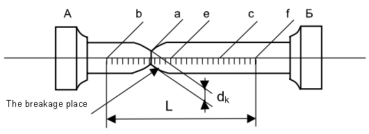
Fig.10. Determining the percentage of elongation and reduction
The reduction in the area of a cylindrical specimen can be determined using the middle value of the diameter in the rupture place, calculated in two mutually perpendicular directions. In the case of testing the plate specimens (GOST 1497-84), as a rule, it is not recommended to determine the value of the reduction in the area. If it is necessary to determine area of the cross-section area АК in the rupture place, it can determined by multiplication of the maximum length of the specimen in the rupture place m and the minimum thickness n.
The percentage reduction in the area after breaking is determined by the formula
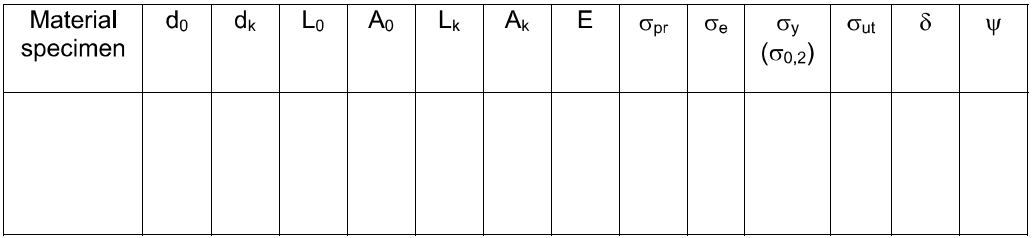
12.8. Determine the grade of the material by the results of virtual testing from table 2, taken from the handbook of materials.
Material |
Е |
|
|
( ) |
|
|
|
MPa |
% |
||||||
Steel Ct.3 |
206000 |
198 |
207 |
235 |
410 |
26 |
65 |
Steel H18K9MST |
190000 |
|
|
2050 |
2100 |
8 |
57 |
Steel 30XrCH2A |
195000 |
1100 |
|
1500 |
1750 |
7 |
|
Cast iron C410 |
60000 |
|
|
|
210 |
0,2 |
|
Cast iron B435 |
170000 |
|
|
220 |
350 |
22 |
|
Brass J196 |
|
|
|
62 |
220 |
52 |
82 |
Report
The report must include:
1. The title page.
2. The goal of the work.
3. The description of equipment and specimens.
4. Tension diagram and its processing.
5. The testing results.
6. Test questions answered.
7. Conclusion.