

11.5. Determining the factor of safety under the symmetrical cycle
The fatigue strength of real details is less than the fatigue strength of laboratory specimen in consideration of the joint influence of the above enumerated factor. They are calculated by the formula
![]() (11.14)
(11.14)
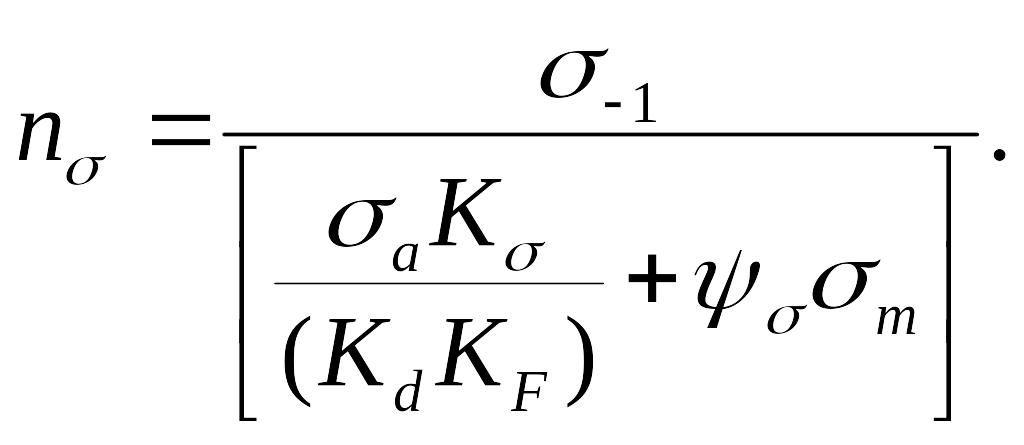
Knowing the maximum symmetrical cycle stress under which a given detail must work we can find the fatigue factor of safety:
![]() (11.15)
(11.15)
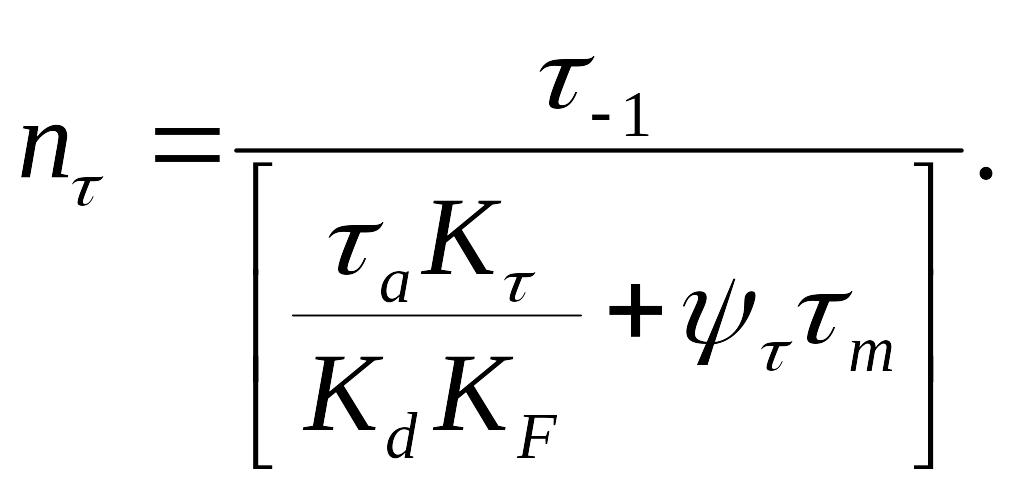
Analogically the factor of safety and in torsion is determined:
![]() (11.16)
(11.16)
Under the combined stress condition the factor of safety is usually calculated by the formula:
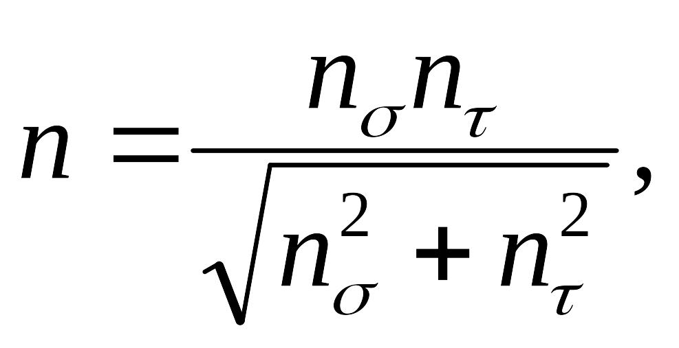 (11.17)
where
![]() and
and
![]() are determined by the formulas (11.15) and (11.16).
are determined by the formulas (11.15) and (11.16).
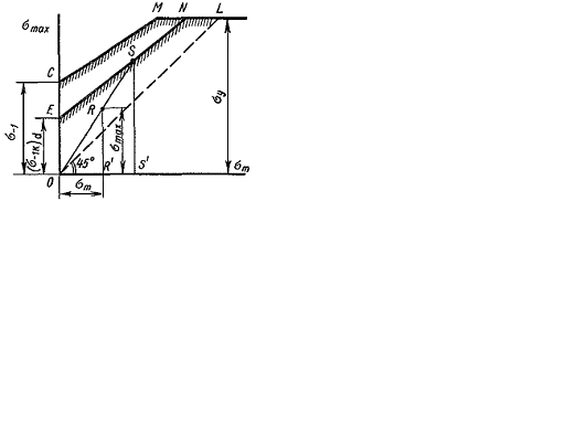
11.6. Determining the factor of safety under the asymmetrical stress cycle
For designs
under the asymmetrical stress cycle the simpled diagram CML of the
limit specimen stress is accepted (see Fig. 11.6 and 11.15). Taking
into account the stress concentration, the influence of the absolute
detail cross section dimensions, the surface condition we can draw
the diagram of the limit detail stresses. There by according to the
given experiences the enumerated factors influence is dated to only
the variable composing cycle i.e. the amplitude
![]() The limit stress amplitude for the specimen according to the formula
(11.15) is
The limit stress amplitude for the specimen according to the formula
(11.15) is
![]() (11.18)
(11.18)
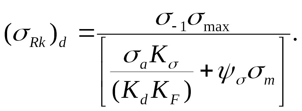
The limit stress amplitude for the detail according to the stated above is equal to
![]() (11.19)
(11.19)
The line equation of the limit stresses EN (Fig. 11.15) to the detail we get the form
![]() (11.20)
(11.20)
Here the current coordinates are denoted by strokes.
Now
calculate the details factor of safety under the variable stress
action
![]() and
(the point R
of the diagram, Fig. 11.15).
and
(the point R
of the diagram, Fig. 11.15).
Development type
Detail
Fig. 11.15.
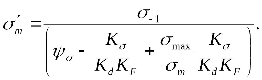
Suppose
that under the detail load increase we have the relation
![]() This loading is called simple.
This loading is called simple.
In this case the limit point according to the rupture is point S.
The safety factor is equal to the relation of the segments SS’ and RR’:
![]() (11.21)
(11.21)
We will
find the value
![]() (the point ordinate S) as the result of combined solving the line
equations of the line EN
and
the line OS.
The line equation has the form:
(the point ordinate S) as the result of combined solving the line
equations of the line EN
and
the line OS.
The line equation has the form:
![]() (11.22)
(11.22)
(The current coordinates are denoted by the strokes).
Equating the right formula parts (11.20) and (11.22) we get
![]() (11.23)
(11.23)
from which
 (11.24)
Substituting the value to the formula (11.20) or (11.22) we find the point coordinate S.
We will
find the value
![]() (the point ordinate S)
as the result of combined solving the line equation of the line EN
and the line OS.
The line equation OS
has
the form:
(the point ordinate S)
as the result of combined solving the line equation of the line EN
and the line OS.
The line equation OS
has
the form:
 (11.25)
Consequently, the following finished relation for determining the safety factor is based on the formulas (11.21):
 (11.26)
Analogically we have in torsion:
 (11.27)
Under the combined stress condition, for example, in torsion with bending the safety factor is calculated by the formula
(11.28)
and the
values
![]() and
are calculated by the formulas (11.26) and (11.29).
and
are calculated by the formulas (11.26) and (11.29).
Except the safety factor of the fatigue strength it is necessary to find the safety factor of the plastic deformations strength as the point s can occur above the line ML. The safety factor of the plastic deformations strength is calculated by the formula
![]() (11.29)
(11.29)
![]() (11.30)
(11.30)
The design
safety (real) factor is less of the factors calculated by the formula
(11.26) or (11.29) or in torsion accordingly to the formula (11.27)
or (11.30). In the case of the design under bending with torsion in
the formula to determine the general safety factor the lesser of the
values
and
![]() calculated as pointed above must be substituted.
calculated as pointed above must be substituted.