

11. Stress analysis under the stresses changing cyclically in time
11.1. Basic definitions
A lot of machine details in their function time are repeatedly subjected to variable loads stresses in time.
For example, the carriage axle working in the bend and rotating together with the wheels suffer changing cyclically stresses although the external forces conserve their values and directions. The axle fibers are either in tension or in compression.
It is highly significant that under the action of the repeated changing loads the fracture occurs as the result of the gradual fracture development called the fatigue fracture. The term «fatigue» is obliged by its origin to the erroneous assumption of the first investigators of this nature about the fact that under the action of variable stresses the metal structure changes.
In the present it is established that the metal structure under the action of the periodical loads does not change. The fracture fatigue nature is conditioned by the peculiarity of the molecular and crystalline substance structure. Apparently, it is concluded in the heterogeneity of the material structure. The separate metal crystal has a different strength in different directions. Therefore, the plastic deformations arise in a separate crystal under certain stresses.
Under the repeated loads and unloadings the strain-hardness arises and the material brittleness increases. Finally, the material ability to the hardness is exhausted and the microcrack arises on one of the crystal sliding planes under the large number of the load reiteration. The appeared crack itself becomes the powerful concentration of stresses and becomes the place of final failure with the consideration of the increasing section weakening.
Two zones in the section where the failure takes place can be clearly differed: the zone with the smooth close-sitting surface (the zone of the gradual crack fatigue development) and the zone with the rough surface.
In Fig. 11.1 the photograph of the destroyed rail section is represented. It is visible that the smooth close-fitting surface arisin as the result of the gradual crack fatigue development around the internal crack which was left in the rail after its rolling; further there is a rough section surface where the final failure of the rail took place due to the large reduction of its section.
Fig. 11.1.
The defect of the internal material structure (the internal cracks, the slag inclusions and the like) and the defect of the detail surface treatment (scratches, traces from the chisel or the grinding stone and so on).
The process of the gradual material damage accumulations under the actions of the variable stresses leading to the property change, the crack formation, its development and failure is called the fatigue and the failure on account of the fatigue crack diffusion is called the fatigue failure.
The material property to resist to the fatigue is called the fatigue strength.
The researches show that the breakdown of the machine parts in the majority cases occurs because of the fatigue crack.
In a general case loads and the stresses can change in time under very complicated laws. The variable stresses can have the stationary and non-stationary modes.
Under the non-stationary mode the change law of stresses in time can be any.
Under the stationary mode the change stresses in time have a repeated (periodical) character. In a certain interval of time (period) the precise repetition of stresses takes place.
The total combination of the consequent stress values for one period of its change, under regular loading is called the stress cycle.
The curves of changing in time of normal and shear stresses in the motor bent axie at one revolution are presented in Fig. 11.2 a, b. As we see the stresses change by a very complicated law but they have a periodical (cyclic) character.
The influence of the stress change curve shape on the fatigue strength is studied insufficiently but this influence is small and the value of the maximum and minimum cycle stresses and their relation play a decisive role. Therefore in future we will suppose that the stress change in time arises accordingly to the law near to the sinusoid (Fig. 11.3 a).
The cycle of variable stresses is characterized:
1) by the
maximum algebraic stress value of the cycle
![]()
2) by the
minimum algebraic stress value of the cycle
![]()
3) by the average stress of the cycle
a)
b)
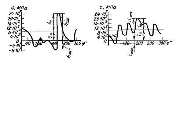
Fig. 11.2.
![]() (11.1)
(11.1)
The average stress of the cycle is the constant cycle component in time (positive or negative);
4) by the cycle stress amplitude
![]() (11.2)
(11.2)
the cycle stress amplitude is the maximum (positive) value of the stress cycle component;
5) by the coefficient of the cycle asymmetry of the stresses
![]() (11.3)
(11.3)
The cycles having the same value R are called similar.
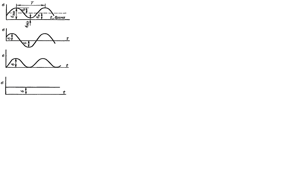
а)
b)
c)
d)
Fig. 11.3.
From the formulas (11.1), (11.2) and Fig. 11.3 we see that
![]() (11.4)
(11.4)
![]() (11.5)
(11.5)
In the case
if
![]() we have the symmetrical
stress cycle
(Fig. 11.3 b). Under that
we have the symmetrical
stress cycle
(Fig. 11.3 b). Under that
![]()
The stress cycle represented in Fig. 11.3 c is called pulsating.
For this case we have
![]()
![]()
The constant statically stress (Fig. 11.3 d) we can consider as a special case of a variable one with the characters
![]()
Any
symmetrical stress cycle can be represented by the sum of the
symmetrical cycle with the maximum stress which is equal to the
amplitude of the given cycle and the constant stress which is equal
to the middle stress of the given cycle (Fig. 11.3 a). All
given terms and relations after the replacement
![]() into
into
![]() remain in force for the case of the variable shearing stress.
remain in force for the case of the variable shearing stress.