
- •1. Основные понятия и положения 11
- •2. Центральное растяжение и сжатие стержня 17
- •3. Геометрические характеристики плоских сечений 42
- •4. Кручение 49
- •5. Изгиб стержней 57
- •Introduction 173
- •1. Basic concepts and principles 175
- •2. Tension and compression of a bar 181
- •3. Geometric characteristics of cross sections 202
- •4. Torsion 208
- •5. Bending of bars 216
- •Index 405 введение
- •1. Основные понятия и положения
- •1.1. Задачи сопротивления материалов, основные гипотезы и допущения
- •1.2. Типы нагрузок и деформаций
- •1.3. Определение внутренних усилий методом сечений. Напряжения
- •2. Центральное растяжение и сжатие стержня
- •2.1. Напряжения и продольная деформация при растяжении и сжатии
- •2.2. Закон Гука при растяжении и сжатии
- •2.3. Поперечная деформация при растяжении и сжатии
- •2.4. Диаграмма растяжения низкоуглеродистой стали
- •2.5. Потенциальная энергия деформации при растяжении
- •2.6. Расчеты на прочность при растяжении и сжатии
- •2.7. Статически неопределимые задачи
- •2.8. Напряжения в наклонных сечениях при растяжении (сжатии) в одном направлении
- •2.9. Закон парности касательных напряжений
- •2.10. Определение напряжений в наклонных сечениях при растяжении (сжатии) в двух направлениях
- •2.11. Определение главных напряжений и положения главных площадок
- •2.12. Зависимость между деформациями и напряжениями при плоском и объемном напряженных состояниях (обобщенный закон Гука)
- •2.13. Работа внешних и внутренних сил при растяжении (сжатии). Потенциальная энергия деформации
- •3. Геометрические характеристики плоских сечений
- •3.1. Статический момент площади
- •3.2. Полярный момент инерции
- •3.3. Осевой момент инерции
- •3.4. Момент инерции при параллельном переносе осей
- •3.5. Главные оси и главные моменты инерции
- •4. Кручение
- •4.1. Определение крутящего момента
- •4.2. Определение напряжений в стержнях круглого сечения
- •4.3. Деформации и перемещения при кручении валов
- •4.4. Потенциальная энергия при кручении
- •5. Изгиб стержней
- •5.1. Типы опор балок
- •5.2. Определение опорных реакций
- •5.3. Определение внутренних усилий при изгибе
- •5.4. Правило знаков для изгибающих моментов и поперечных сил
- •5.5. Дифференциальные зависимости при изгибе
- •5.6. Построение эпюр изгибающих моментов и поперечных сил
- •5.7. Определение нормальных напряжений
- •5.8. Условия прочности по нормальным напряжениям
- •5.9. Потенциальная энергия деформации при изгибе
- •5.10. Теорема о взаимности работ. Теорема о взаимности перемещений
- •5.11. Определение перемещений методом Мора
- •6. Теории прочности
- •6.1. Назначение гипотез прочности
- •6.2. Первая гипотеза прочности
- •6.3. Вторая и третья гипотезы прочности
- •6.4. Энергетические гипотезы прочности
- •7. Сложное сопротивление
- •7.1. Изгиб в двух плоскостях (косой изгиб)
- •7.2. Изгиб с растяжением (сжатием)
- •7.3. Внецентренное сжатие (растяжение)
- •7.4. Кручение с изгибом
- •7.5. Кручение с растяжением (сжатием)
- •7.6. Пример расчета вала на изгиб с кручением
- •8. Расчет тонкостенных сосудов
- •9. Расчет сжатых стержней на устойчивость (продольный изгиб)
- •9.1. Устойчивые и неустойчивые формы равновесия
- •9.2. Формула Эйлера для критической силы
- •9.3. Влияние способа закрепления концов стержня на критическую силу
- •9.4. Пределы применимости формулы Эйлера
- •9.5. Эмпирические формулы для определения критических напряжений
- •9.6. Практическая формула для расчета на устойчивость
- •10. Динамическое действие нагрузок
- •10.1. Динамические нагрузки
- •10.2. Вычисление напряжений при равноускоренном движении
- •10.3. Определение перемещений и напряжений при ударе
- •11. Расчет на прочность при напряжениях, циклически изменяющихся во времени (расчет на усталость)
- •11.1. Основные определения
- •11.2. Кривая усталости при симметричном цикле. Предел выносливости
- •11.3. Диаграммы предельных напряжений и амплитуд цикла
- •11.4. Факторы, влияющие на предел выносливости
- •11.5. Определение коэффициента запаса прочности при симметричном цикле
- •11.6. Определение коэффициента запаса прочности при асимметричном цикле напряжений
- •Предположим, что при увеличении нагрузки на деталь отношение Такое нагружение называется простым.
- •11.7. Практические меры повышения сопротивления усталости
- •Практикум Лабораторная работа № 1
- •Введение
- •Установка
- •Порядок выполнения
- •Контрольные вопросы
- •Литература
- •Лабораторная работа № 2
- •Введение
- •Установка
- •Порядок выполнения
- •Контрольные вопросы
- •Литература
- •Лабораторная работа № 3
- •Введение
- •Установка
- •Порядок выполнения
- •Introduction
- •Basic concepts and principles
- •Tasks, main hypothesis and assumptions of the strength of materials
- •1.2. Types of loads and deformations
- •1.3. Determining the internal forces by the method of sections. Stresses
- •2. Tension and compression of a bar
- •2.1. Stresses and a longitudinal deformation in tension and compression
- •2.2. Hooke,s law in tension and compression
- •2.3. The transverse deformation in tension and compression
- •2.4. The tension diagram of the lowcarbon steel
- •2.5. The potential deformation energy in tension
- •2.6. Strength calculation in tension and compression
- •2.7. Statically indeterminate problems
- •2.8. Stresses at inclined sections under tension (compression) in one direction
- •2.9. Law of the shearing stresses couple
- •2.10. Determination of stresses at the inclined sections in tension (compression) in two directions
- •2.11. Determining the principal stresses and the principal planes position
- •2.12. The relation between the deformations and the stresses for the plane and general stresses (a general form of Hook’s law)
- •2.13. The work of the external and internal forces in tension (compression). Strain energy
- •3. Geometric characteristics of cross sections
- •3.1. First moment of an area
- •3.2. Polar moment of inertia
- •3.3. Axial moment of inertia
- •3.4. The moment of inertia at parallel displacement of axis
- •3.5. Principal axes and principal moment of inertia
- •4. Torsion
- •4.1. Determining the twisting moment
- •4.2. Determining the stresses in the round section bar
- •4.3. The deformations and displacements in the shaft torsion
- •4.4. Internal strain energy in torsion
- •5. Bending of bars
- •5.1. Types of the beam support
- •5.2. Determining the support reactions
- •5.3. Determining the internal stresses in bending
- •5.4. The sign rule for the bending moments and the shearing forces
- •5.5. The differential relationships in bending
- •I.E. The intensity of the distributed load is equal to the derivative of the shearing force with respect to the bar section abscissa.
- •I.E. The shearing force is equal to the derivative of the bending moment with respect to the bar section abscissa.
- •I.E. The second derivative of the bending moment with respect to the bar section abscissa is equal to the intensity of the distributed load.
- •5.6. Drawing bending moment and shearing force diagrams
- •5.7. Determining the normal stress
- •5.8. Strength conditions with normal stresses
- •5.9. Strain energy in bending
- •5.10. Betty’s reciprocal theorem. Reciprocal displacement theorem
- •5.11. Determining displacements by Mohr’s method
- •6. Strengtn theory
- •6.1. The purpose of strength hypotheses
- •6.2. The first strength hypothesis
- •6.3. The second and third strength hypotheses
- •6.4. The energy hypotheses of strength
- •7. Combined stress
- •7.1. Bending in two planes (non-uniplanar bending)
- •7.2. Combined axial tension (compression) and bending
- •7.3. Eceentrical tension (compression)
- •7.4. Combined torsion and bending
- •7.5. Combined torsion and compression
- •7.6. Example of the shaft calculation in bending with torsion
- •8. Calculation of the thin-walled vessels
- •9. Stability analysis of the bars in compression (buckling)
- •9.1. Stable and unstable equilibrium forms
- •9.2. Euler’s formula for the critical force
- •9.3. Influence of bar end conditions on the critical force
- •9.4. Applicability limits of of Euler’s formula
- •9.5. Empirical formula for determining the critical stresses
- •9.6. The practical formula for the stability analysis
- •10. Dynamic load action
- •10.1. Dynamic load
- •10.2. Calculating stresses under the uniformly accelerated motion
- •10.3. Determining displacements and stresses under the impact
- •11. Stress analysis under the stresses changing cyclically in time
- •11.1. Basic definitions
- •11.2. Fatigue (Wohler’s) curve under the symmetrical cycle. Fatigue strength
- •11.3. The limit stress diagram and the cycle amplitude
- •11.4. Factors influencing on the fatigue strength
- •11.5. Determining the factor of safety under the symmetrical cycle
- •11.6. Determining the factor of safety under the asymmetrical stress cycle
- •11.7. Practical measures to increase the fatigue strength
- •Practicum Laboratory work № 1
- •Introduction
- •Installation
- •Test specimens
- •Test questions
- •Literature
- •Laboratory work № 2
- •Introduction
- •Installation
- •Test questions
- •Literature
- •Laboratory work № 3
- •Introduction
- •Installation
- •Individual task report
- •Test questions
- •Literature
- •Англо-русский терминологический словарь
- •Список фамилий ученых
- •Greek alphabet
- •Сокращения
- •Единицы измерения
- •Список наиболее употребительных знаков
- •Список использованной литературы
- •Алфавитный указатель
- •Сопротивление материалов
- •625000, Тюмень, ул. Володарского, 38.
- •625039, Г. Тюмень, ул. Киевская, 52
7. Combined stress
7.1. Bending in two planes (non-uniplanar bending)
The non-uniplaner bending arises when the internal forces perpendicular to the bar axis do not lie on the plane passing through the principal axis of its cross section (Fig. 7.1). In this case the bending moment arising at the cross section can be decomposed into two bending moments acting on the planes passing through the principal axes of the section. Thus, the non-uniplanar bending can be considered as the combination of two plane bends on the mutually perpendicular planes.
Under the non-uniplanar bending the normal stresses at any point of the cross section will be equal to the algebraic sum of stresses from bending into both planes.
Let us consider, for example, the point C of the support section having the x and y-conditions about the principal axes.
At the section we have:
the bending moment arising under the bar bending in the vertical plane with the neutral x-axis
(7.1)
the bending moment arising under the bar bending in horizontal plane with the neutral y-axis
(7.2)
Here F and Fh are the vertical and horizontal components of the force F; is the beam length; is the angle of the force plane inclination with respect to x-axis.
The tension stresses arise in the upper half beam (including at the point) under bending in the vertical plane and in the lower half beam compressions arise because the convex bar side will be on the top. The stress at the point C is determined by the following formula already known from the plane bend theory:
(7.3)
Where y is the distance from the neutral x-axis to the point C; Ix is the second moment of the beam cross section x-axis.
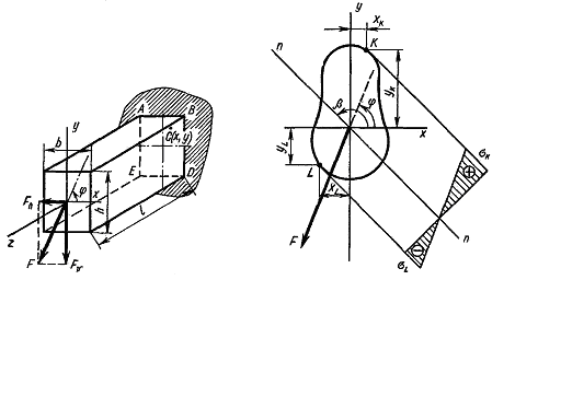
Fig. 7.1. Fig. 7.2.
Because of bending in the horizontal plane the tension stresses arise in the right half beam and consequently at the point C and tension ones arise in the left half beam because the convex bar side under bending in the horizontal plane will be to the right. To be convinced of it bend a flexible ruler in the horizontal plane. The stresses at the point C will be determined by an analogous formula
(7.4)
where x is the distance from the y-axis the neutral axis under bending in the horizontal plane to the point C; Ix is the second moment of the bar cross section about y-axis. The sum stress at the point C is
(7.5)
This formula is also valid for any bar section shape. If the section has the salient angle points for which Xmax and Ymax are achieved simultaneously (a rectangle, a double - T profile), the maximum stresses arise at these points:
(7.6)
where
is the section modulus about the x-axis;
is
the section modulus about the y-axis.
It is evident that the section angle points are dangerous where the stresses with the same sign are added.
For the case represented in Fig. 7.1 such section points will be the points B and E, in this case the point B is in the tension region and the point E is in compression one.
That is why the stresses at the points B and E are equal:
(7.7)
For the section of an arbitrary shape not having jutting angle points it is previously necessary to find the «dangerous» points, i.e. those section points where the maximum tension and compression stresses will act (Fig. 7.2).
At first the position of the zero line in the non-uniplanor bending is determined i.e. the geometric place of the section points at which the normal stresses are equal. In other words the line dividing the section part into tension and compression one is determined. Let it be the line nn.
Under bending the stresses increase according to the distance from the zero line.
It can be seen that the equation (7.5) represents itself the plane equation passing through the zero line. The ordinate measured along the normal from the cross section to this plane is equal numerically to the stress at the given point. It will be maximum for that point which is farther than the rest all from the zero line.
Taking it into consideration we conclude that the points to be verified concerning the stresses will be the ones most remote from the zero line, i.e. the points K and Z. For the material working equally in tension and compression the point with the largest stress arisen is dangerous.
We get the equation of the zero line by making equal the left part of the formula (7.5) to zero:
(7.8)
or
(7.9)
where in accordance with the formulas (7.8) and (7.9) we have
(7.10)
and x0 and y0 are the running coordinates of the zero line points. As Mx=0 then
(7.11)
This is the equation of the zero line.
We can see that this is the straight-line equation, the line passing through the coordinate system origin. By dividing both parts of the equation by x0 we get
(7.12)
But the
relation
is the tangent of the incline angle of the zero line to x-axis, i.e.
its angle coefficient. Hence,
or
(7.13)
We can see from this equation that the angle is not equal to the angle under Ix≠Iy i.e. the zero line is not perpendicular to the force line as it was at a plane (simple) bending. Only in the special case when Ix=Iy (a circle, a square and the like) we have
(7.14)
Hence, in this special case (Ix=Iy) the zero line is perpendicular to the force line, i.e. we have the plane bending.