

5.8. Strength conditions with normal stresses
To ensure the bar strength it is necessary that the maximum tension and maximum compression stresses under bending in a dangerous section, i.e. in the section where M has the maximum value, should not surpass the corresponding allowable working stress (only bars with the constant section along the length are considered).
Denote
(Fig. 5.10 b) by
![]() the distance from the neutral axis to the most remote tension fiber,
by hc
the distance to the most compressed fiber. Then the most tension
stress under bending is
the distance from the neutral axis to the most remote tension fiber,
by hc
the distance to the most compressed fiber. Then the most tension
stress under bending is
![]() (5.15)
(5.15)
the most compression stress (with an absolute value) is
![]() (5.16)
(5.16)
The allowable working stresses in tension and compression are different for brittle materials. Therefore for the beams made of these materials the sections are usually applied which are asymmetrical with respect to the neutral axis. So the section then is located that ht < hc. In this case two conditions for the strength are to be composed:
with the maximum tension stresses
![]() (5.17)
(5.17)
with the maximum compression stresses
![]() (5.18)
(5.18)
where
![]()
![]() are the section modulus of the tension and compression fibers.
are the section modulus of the tension and compression fibers.
If the bar section is symmetrical about the neutral axis, we get the formula
![]() (5.19)
(5.19)
Defining
![]() we get the following condition of the strength under the same
allowable working stresses in tension and compression
we get the following condition of the strength under the same
allowable working stresses in tension and compression
![]()
(5.20)
The
value
![]() is called the section modulus under bending.
is called the section modulus under bending.
Example.
Determine the beam section of the double -T profile in the length L=6
m loaded by the uniformly distributed load
![]()
![]()
Solving. For this case the maximum bending moment takes place in the middle beam section:
![]()
The required section modulus is
![]()
Select the
double -T profile of № 45 from the tables of sections which has
![]() (Wx
understressing being < 5%, which is allowable).
(Wx
understressing being < 5%, which is allowable).
5.9. Strain energy in bending
Under bending the work done by the external forces is to change the strain energy of the deformed bar. The work of the external moment Me can be calculated by the formula
![]()
where
![]() is the section rotation angle at the point of the application moment.
is the section rotation angle at the point of the application moment.
The unit work of the bending moment can be found by the formula:
(5.21)
The total work of the bending moment of the beam long L is
(5.22)
In a general case of bending there arise the shearing forces apart from the bending moment at the beam cross section.
However, the strain energy of the shear corresponding to the work of the shearing force is not large – as the research work shows – and it is often neglected.
Therefore the formula (5.23) is useful both for the pure and general case of bending.
![]() (5.23)
(5.23)
5.10. Betty’s reciprocal theorem. Reciprocal displacement theorem
Let us prove the theorem having an important application, that is Betti’s reciprocal theorem. For this consider a deformed line system in two different conditions corresponding to two different loads (Fig. 5.11). For the simplest case to be considered take a simple beam loaded by the simplest load in two conditions (in one concentrated force). The load, the internal forces and deformations corresponding to these conditions are noted by indexes 1 and 2.
The first system state is represented in Fig. 5.11 a and the second in Fig. 5.11 b.
The
displacement in the load direction for the first state of this load
is denoted by
![]() The displacement in the load direction for the second state caused by
the load action of the first state is denoted by
The displacement in the load direction for the second state caused by
the load action of the first state is denoted by
![]() The designations of the displacement of the second state are given in
Fig. 5.11 b. The displacements containing two similar indices, for
example
The designations of the displacement of the second state are given in
Fig. 5.11 b. The displacements containing two similar indices, for
example
![]() and
and
![]() are called principal
and the displacements of kind
are called principal
and the displacements of kind
![]() and the like are secondary.
Now prove Betti’s
reciprocal theorem, namely: the external force work of the first
state on the displacement of the second state is equal to the force
work of the second state on the displacement caused by the forces of
the first state.
and the like are secondary.
Now prove Betti’s
reciprocal theorem, namely: the external force work of the first
state on the displacement of the second state is equal to the force
work of the second state on the displacement caused by the forces of
the first state.
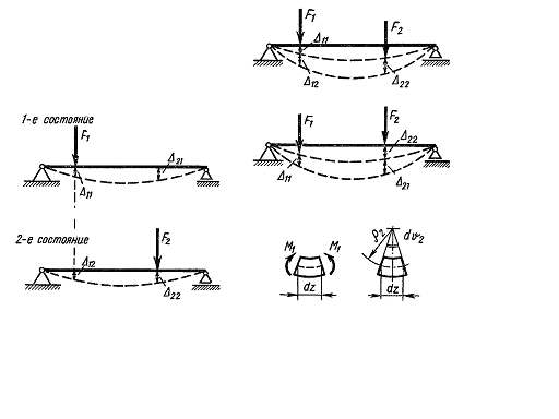

Fig. 5.11. Fig. 5.12.
To prove the theorem let us load the beam by forces F1 and F2 applying them in a different sequence.
To start let us apply the load F1 and then apply the force F2 to the deformed beam (Fig. 5.12 a).
Calculate the work done by the external forces in this case.
The work
done by the force F1
on its displacement
![]() caused by this force is
The work done by the force F2
on its displacement
caused by this force is
The work done by the force F2
on its displacement
![]() is
is
The
additional work of the force F1
on the displacement
![]() caused by the force is
caused by the force is
Pay
attention to that under the calculation of W12
the
multiplier
![]() is missing because the force F on the displacement
fulfils the work, being constant.
is missing because the force F on the displacement
fulfils the work, being constant.
The total work done by the external forces under the first way loading (consequence) is
![]() (5.24)
(5.24)
The actual work W12 done by the force on the displacement caused by the other force (forces) is called additional work. But this work may not be done, and it can be considered only as virtual, i.e. which will be done if the system is loaded by two loads simultaneously. That work is called the virtual (possible) work.
Under further computations we will not differentiate between the additional and virtual works.
2. Load now
the beam in another sequence: first let us apply the force F2
and then the force F1
(Fig. 5.12 b). The work done by the force F2
on its displacement
![]() is
is
(5.25)
The work
done by the force F1
on its displacement
![]() is
is
(5.26)
The work
done the force F2
on the displacement
![]() is
is
![]() (5.27)
(5.27)
The total work in the second way of loading is
![]() (5.28)
(5.28)
But the force work does not depend on the order of their application. Hence, W1=W11, from where we get
![]() (5.29)
(5.29)
or for the case considered
![]() (5.30)
(5.30)
This proves the above formulated theorem about the reciprocal virtual works of the external forces. We have proved it by the example of the concentrated external loads. But the theorem will also be correct for any external load: concentrated, distributed, external moments. It should be kept in mind that the moments work is calculated in this case not on the line but angle displacements.
Analogously there can also be proved the reciprocal virtual work of the internal forces:
![]() (5.31)
(5.31)
Using the energy preservation law it can be shown that the additional work of the external forces is equal to the absolute value of the additional work of the internal forces: and
It follows that
![]() (5.32)
(5.32)
These relations will be used further for the substantiation of the general method of displacements determining (Mohr’s method). The important reciprocal displacement theorem follows from Betti’s reciprocal theorem as the special case.
Taking F1=F2=1 we get
![]() (5.33)
(5.33)
Here the
displacements caused by the forces are equal to the unit and they are
denoted by
![]() and so on.
and so on.
The displacement of the application point of the unit force to its direction caused by a second unit force is equal to the displacement of the application point of the second unit force in the direction of the latter caused by the action of the first unit force.