

5.7. Determining the normal stress
At the plane (simple) pure bend only the bending moments arise at the bar cross section passing through the bar cross section passing through one of the principal axes of the bar cross section. The bending moment is the resultant moment of the internal forces as distributed over the section.
To derive the law of the distribution and value of the internal forces arising at the bar cross section the static equations alone are not enough. It is necessary to use the bar deformation condition.
If subjecting the bar (specimen) with the network drawn on its surface, the following is detected (Fig. 5.9):
1) The lines 1-1 and 2-2 on the bar surface after deforming will turn at some angle d remaining straight. It is supposed that the bar cross-section being flat before the deformation remains flat after the deformation too (the hypotheses of the plane section).
The calculation based on that assumption coordinates with the experience. Since the rectangular network is the same, before and after the deformation the shear stress at the cross section is supposed to be equal to zero.
2) The fiber ab on the convex bar side lengthens, which proves the fact of the fiber tension and the fiber of shortens that proves its compression. The length of the fiber cd doesn’t change that proves the absence of both tension and compression.
The bar layer (the fiber cd) under the bending having neither tension nor compression is called the neutral layer. The cross line of the neutral layer with the plane of the bar cross section (Fig. 5.10 a) is called the neutral axis (line). The crossing of the force plane with the cross section plane is called the force line.
From the experience results considered it follows that the fiber deforms in different ways: the fiber which is farther from the neutral layer has the larger deformation. Show that the deformation is changed by the line law along the bar section height (Fig. 5.9). Indeed, the length b’b’’ is the total lengthening of the fiber ab whose length before the deformation is the same as the fiber length cd belonging to the neutral layer (see Fig. 5.9). The until strain of this fiber is
(5.10)
where ρ is the radius of the bar neutral layer curvature (the value ρ is unknown); y is the distance from the neutral axis to the fiber considered.
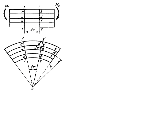
Fig. 5.9.
The bar fibers do not press one another i.e. the stresses in the direction perpendicular to the bar axis is equal to zero. Hence, each fiber is subjected to tension or compression. Then, according to Hook’s law for the uniaxial stress we get
(5.11)
i.e. the normal stress change along the height of the bar cross section is proportional to the distance from the neutral axis. There will be the maximum stresses at the upper and lower section edge. The diagram is shown in Fig. 5.10 a. We shall consider the tension stress as positive.
а) b)
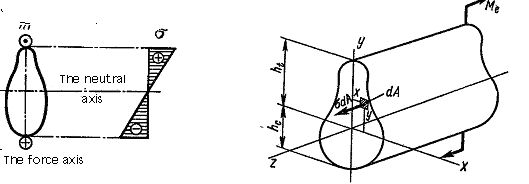
Fig. 5.10.
Having derived the stress distribution law we can also determine the stresses value from the equilibrium equation. Consider the equilibrium of the bar part subjected to the action of the external moment Me and the internal forces, arising at the cross section (Fig. 5.10 b). Under the equilibrium of this bar part six equations of the equilibrium have to be kept: the projection sum of the acting force on three coordinate axes, three moment sums about x, y, z - axes being equal to zero.
Equate to zero the projection sum on y-axis:
The same for x-axis: But and turn into identities because the internal forces σdA are perpendicular to these axes.
Equate to zero the projection sum on the z-axis:
![]() or
or
![]()
We get
![]()
But
![]() as soon as
as soon as
![]() the bend bar is to be considered.
the bend bar is to be considered.
Hence,
This integral represents the first moment of the bar cross-section area about the neutral axis. It is equal to zero, hence, the neutral axis under bending passes through the centroid of the cross section.
The equation turns into an identity because the internal stresses σdA are parallel to z-axis.
The equation gives
 Using
the formula (5.11) we get
Using
the formula (5.11) we get
But
hence,
![]() The integral
The integral
![]() is the product of the inertia cross section with respect to the x
and y-axes.
As soon as it is equal to zero, the x
and y-axes
are to be the principal axes of the section and the moment Me
has
to lie on the plane passing through one of the principal axes, which
is fulfilled under the plane bending. From this condition it also
follows that
the force line and the neutral axis are mutually perpendicular.
is the product of the inertia cross section with respect to the x
and y-axes.
As soon as it is equal to zero, the x
and y-axes
are to be the principal axes of the section and the moment Me
has
to lie on the plane passing through one of the principal axes, which
is fulfilled under the plane bending. From this condition it also
follows that
the force line and the neutral axis are mutually perpendicular.
Equate to zero the moments sum of the forces with respect to the x-axis:
![]()
Using the
formula (5.11) we get
![]() and
and
![]()
The
integral Jx
is the second moment of the section area about the neutral x-axis.
Some external moments as well as any other load can influence on the
bar cut part. In this case the equilibrium equation
![]() contains the algebraic moments sum of all the forces and it is equal
to the bending moment at the cross section M.
The above said remembered relation will be presented by
contains the algebraic moments sum of all the forces and it is equal
to the bending moment at the cross section M.
The above said remembered relation will be presented by
![]() (5.12)
(5.12)
from this
![]() (5.13)
(5.13)
The value is the curvature of the bar neutral layer.
It was shown above that the neutral line of the cross section passes through the centroid. Hence, the bar axis (longitudinal axis) being the geometric place of the cross section centroid is located on the neutral layer. In this way we get the expression (5.13) determining the curvature of the bar axis.
So, the bar axis curvature under bending is proportional to the bending moment and inversally proportional to the value EIx called the flexural rigidity.
Substituting the value found into (5.11) we get the important formula
![]() (5.14)
(5.14)
allowing us to determine the normal stress at any point of the bar cross-section.
The formula (5.14) is derived for the pure bending.
Under the cross bending there arise both normal and shearing stresses at the bar cross-section.
The appearance of shearing stresses is accompanied by appearance of the shearing strain and as a result the bar cross sections are no longer plane i.e. pressing fibers against each other takes place there.
The more detailed analysis shows that the formula (5.14) gives quite reliable results also under the cross bending.