

Установка
В этой работе для испытаний используется изгибно-вращательная машина, обеспечивающая чистый изгиб круглых образцов (рис.3).
Рис
3. Схема машины изгибно-вращательного
типа для испытания круглых образцов
на чистый изгиб при вращении образцов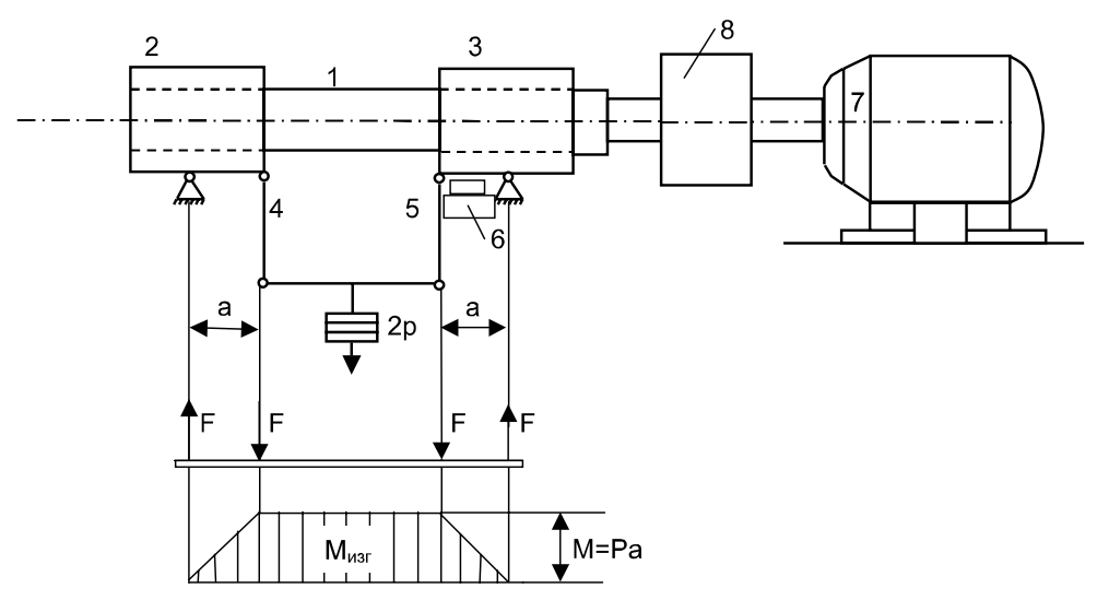
Образец 1 зажат во вращающихся цангах 2 и 3. Усилие передается от груза, подвешенного на серьгах 4 и 5. Счетчик 6 фиксирует число циклов N. Когда образец ломается, происходит автоматическое отключение двигателя 7 от контакта 8. На рис. 3 показана эпюра изгибающих моментов.
Н![]() ормальные
наибольшие напряжения от изгиба
определяются по формуле
ормальные
наибольшие напряжения от изгиба
определяются по формуле
Где d - диаметр образца в рабочей части,
W - момент сопротивления поперечного сечения образца,
М - изгибающий момент, F - нагрузка.
О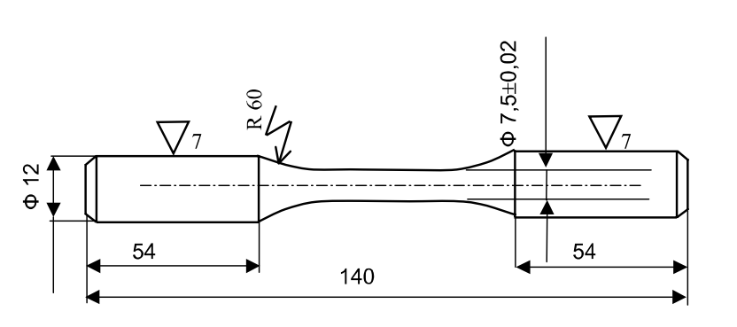 бразец
для испытаний изготовляется в соответствии
с ГОСТ'ом 25.502-79 (рис. 4).
бразец
для испытаний изготовляется в соответствии
с ГОСТ'ом 25.502-79 (рис. 4).
Рис 5. Образец для испытаний
Порядок выполнения
1. Выбрать схему нагружений.
2. Выбрать машину или стенд для испытаний.
3. Задаться базовым числом испытаний N=107.
4. Задать наибольшее напряжение цикла для первого образца
![]() .
.
5. Установить образец в машину.
6. Установить
грузы, соответствующие напряжению
![]() .
.
7. Включить электродвигатель машины.
8. Проводить нагружение образца до разрушения.
9. Записать число циклов N, которое выдержал образец.
10. Повторить
поз. 4 для второго образца, задавая
![]() и
поз.
и
поз.
![]() .
.
11. Повторить для остальных образцов поз. 10, снижая на 0,1 .
12. По данным испытаний и N построить кривую усталости
(рис. 2).
13. По кривой усталости определить предел выносливости .
Отчет
о выполнении индивидуального задания
Ф.И.О студента _________________
Группа ________________________
Лабораторная работа № ___
Тема: ___________________
Отчет должен содержать:
Титульный лист.
Цель работы.
Описание оборудования и образцов.
Протокол испытаний.
Ответы на контрольные вопросы.
Выводы.
Контрольные вопросы
Что такое предел усталости?
Природа разрушений от усталости.
Как определяется амплитуда напряжений цикла?
Какие характеристики напряжений цикла влияют на сопротивление усталости?
Какие виды испытаний на усталость применяются?
Литература
Александров А.В., Потапов В.Д., Державин Б.П. Сопротивление материалов: Учеб. Для ВУЗов. - М.: Высш.шк., 1995. -560с.
Феодосьев В.И. Сопротивление материалов. - М.: Наука, 1986. -512с
Школьник Л.М. Методика усталостных испытаний. Справочник - М.: Металлургия, 1978. - 304с.
Introduction
The present handbook is written in agreement with the state educational standard of the higher professional education on the subject “Strength of materials”. All hard bodies have the strength and stiffness properties i.e. they can in certain limits perceive the external force action without rupture and geometric dimensions material changes. These properties attracted the human attention at the remote times when a man was trying to make the first primitive tools and house-hold articles.
The science of the strength of materials arose in the Renaissance Epoch when the development of engineering, trade, navigation, military science demanded scientific substantiations necessary for building big ships, bridges, hydrotechnical constructions and other complicated constructions. Italian scientist Galileo (1564-1642) is considered to be the propounder of the science.
The strength and stiffness demand attention, qualitative appreciations and certain quantitative measure. The science studying them is called the mechanics of rigid bodies and the educational subject which puts a student in the world of engineering stress analyses and stiffness is called the strength of materials. Strength of materials is a part of the rigid bodies mechanics, but not only. Mechanics of rigid bodies includes other subjects such as the mathematical theory of elasticity which considers the same questions as in the strength of materials but it is performed in a more detailed form.
The engineering science structural mechanics studies the design problems of different types of buildings, machines and their supporting constructions composed of bars, plates and shells for strength, stiffness and buckling. Thus, the strength of materials creates the bases for a proper structural design. It studies the basic deformation types such as tension, compression, torsion and bending bars, mechanics of these deformations development and the ways of the strength appreciation. Alongside with the introduction of the corresponding concepts great attention is paid to the ability to represent the construction element work by the consciously simplified calculating diagram and corresponding analytical correlations which are generally called creating physic-mathematical model of the element work or its construction part. Correctly and competently created design models allow to solve numerous important engineering problems: to give the strength appreciation of the present construction; to determine the limit allowable loads; to choose the needed element dimensions and suitable materials ensuring their strength and efficiency, i.e. to find the parameters ensuring to a certain extent the best properties of this construction and so on.
Studying the strength of materials requires good knowledge of physics, mathematics, theoretical mechanics and it essentially bases on the rules studied in these subjects. The knowledge of the strength of materials fundamentals is the important demand and component part in the process of professional education. The methods of mathematical theory of elasticity lead a student from general to particular. They are characterized by the mathematical rigour, exact and profound analysis, also by the complexity of the mathematical apparatus.
The statement of the strength of materials is done by the opposite principle – from particular to general. The basic purpose is to create practically acceptable simple methods to calculate typical the most common construction elements. Strength of materials and the elasticity theory are interrelated. The course of the strength of materials accepts much from the elasticity theory and naturally applies it in its content. New parts of the mechanics studying the problems of the deformed bodies arised and developed among sciences occupying the intermediate position between the strength of materials and the elasticity theory; the related subjects such as the theory of plasticity, the theory of creep and others appeared.
The methods of the strength of materials do not stay constant. They change simultaneously with new problems arising and new practical tasks.