

Frequency
Рис. 3.19. Частотные зависимости сопротивления связи Z12 и полного сопротивления Zb
внешнего проводника коаксиального кабеля.
Fig. 3.19 - The frequency dependences of the coupling resistance Z12 and the impedance Zb
of the coaxial cable external conductor.
a42
Приведенные выше соображения справедливы, если коаксиальная цепь является источником собственных помех. Но они могут быть использованы также на случай, когда коаксиальная цепь подвержена внешнему влиянию (источник помех расположен вне цепи).
В этом случае ток концентрируется на внешней поверхности внешнего проводника коаксиального кабеля (см. рис. 3.20).

Рис. 3.20. Распределение величины во внешнем проводнике коаксиального кабеля:
а) источник энергии [ Г ] внутри цепи; б) источник энергии [ Г ] вне цепи.
Fig. 3.20 - Distribution the value in the external conductor of the coaxial cable:
a) energy source is inside of circuit; b) energy source is outside of circuit
Сопротивление связи Z12 [Ом/км] определяется так же, как и сопротивление внешнего проводника коаксиального кабеля, только напряжённость поля Ez принимается не на внутренней поверхности внешнего проводника (где радиус r = rb ), а на внешней поверхности внешнего проводника (r = rс ):
 (3.43)
где
 – коэффициент вихревых токов, 1/м;
rb и rc – внутренний и внешний радиусы внешнего проводника, mm;
Δ = (rc - rb ) – толщина внешнего проводника, мм;
 – проводимость
внешнего проводника, Ом.м/мм2;
– проводимость
внешнего проводника, Ом.м/мм2;

Значения
модуля параметра
 ,
необходимые для расчёта сопротивления
связи внешнего медного и алюминиевого
проводников коаксиального кабеля
приведены в таблице 3.1 (смотри
[ 1 ], стр. 237).
,
необходимые для расчёта сопротивления
связи внешнего медного и алюминиевого
проводников коаксиального кабеля
приведены в таблице 3.1 (смотри
[ 1 ], стр. 237).
Для коаксиальных кабелей со стальными экранами в виде спирально намотанной ленты формула для Z12 имеет более сложный вид чем (3.43).
The considerations, which brought above, are correct if the coaxial circuit is a source of the self-generated noise. But these considerations can be used as well for the event, when coaxial circuit is respondent circuit from the external influence (the noise source is located outside of the circuit). In this case current concentrates on the external surface of the external conductor of the coaxial cable (look at the Fig. 3.20).
The coupling resistance Z12 [Ohm/km] is defined as well as the resistance of the external conductor of the coaxial cable, only field density Ez is taken not on the internal surfaces of the external conductor (where radius r = rb ), but on the external surface of the external conductor (r = rс ):
(3.43)
where – coefficient of eddy current, 1/mm;
rb and rc – internal and external radiuses of an external conductor, mm;
Δ – thickness of the external conductor, mm;
–conduction of the external conductor, Ohm.m/mm2;
 ,
Ohm/km.
,
Ohm/km.
{ sinh(x) = (ex-e-x)/2 }
The values of the module of the parameter which are required for calculation the coupling resistance Z12 of the external copper and aluminum conductor of the coaxial cable were provided in the Table 3.1 (see [ 1 ], p. 237).
For the coaxial cables with the steel-cord belt shields the formula for Z12 has a more complex type than formula (3.43).
Table 3.1 – Dependence of the parameter from frequency f and thickness of conductor Δ
Frequency f, kHz |
Value |N|, Ohm/km, at the thickness of conductor Δ, mm |
|||||
Δ = 0,1 |
Δ = 0,15 |
Δ = 0,2 |
Δ = 0,25 |
Δ = 0,3 |
Δ = 0,5 |
|
Copper |
||||||
10 60 100 200 300 500 |
181 177 176 175 174 168 |
120 116 115 114 110 99 |
87 86 85 81 73 59 |
69 68 66 56 50 35 |
56 55 53 44 34 19 |
40 27 21 11 6 2 |
Aluminum |
||||||
10 60 100 200 300 500
|
296,7 295 294,4 293,9 293,5 292,2 |
197 196,5 196,4 194,3 193,2 187,5 |
147,5 147 146,6 144,7 139,8 128,1 |
117,9 117,3 116,1 111,4 104,1 87,4 |
98,2 97,2 95,2 87,5 77,7 58,6 |
58,8 54,3 47,9 33,7 22,3 11,44 |
Лекция № 9
Lecture # 9
3.9. ПЕРЕХОДНОЕ ЗАТУХАНИЕ МЕЖДУ КОАКСИАЛЬНЫМИ ЦЕПЯМИ
3.9. THE transient attenuation BETWEEN coaxial CIRCUITS
a43
Уравнения влияния,
методика расчёта и формулы переходного
затухания в коаксиальных цепях такие
же, как в симметричных. Разница заключается
лишь в параметрах электромагнитной
связи. В симметричных цепях влияние
обусловлено поперечными электрическим
 и
магнитным
и
магнитным полями
и соответствующими связями K12,
M12 (см.
формулы (3.2), (3.4) из лекции №1). Причём,
на ближнем конце эти связи суммируются
полями
и соответствующими связями K12,
M12 (см.
формулы (3.2), (3.4) из лекции №1). Причём,
на ближнем конце эти связи суммируются
 ,
а на дальнем - вычитаются
,
а на дальнем - вычитаются
 (см. формулы (3.26) и (3.29)).
В коаксиальных цепях внешнее поперечное поле отсутствует и имеется лишь продольное поле Ez, которое создаёт падение напряжения в соседних цепях. Это влияние рассчитывается через параметр сопротивления связи Z12 и по своей природе аналогично магнитному влиянию M12 в симметричных цепях. Электрическое влияние в коаксиальных цепях отсутствует, так как электрическое поле замыкается внутри кабеля между проводниками цепи (K12 = 0). Магнитная связь между коаксиальными цепями определяется выражением:
 ,
(3.44)
,
(3.44)
где Z12 – сопротивление связи влияющей цепи; Z21 – сопротивление связи цепи, подверженной влиянию; Z3 = Z11 + Z22 + iωL3 – полное сопротивление третьей, промежуточной цепи;
Z11 и Z22 – собственные сопротивления внешних проводников влияющего и подверженного влиянию кабелей; jωL3 – внешнее индуктивное сопротивление III цепи (которая образована из влияющего и подверженного влиянию кабелей). Если коаксиальные цепи соприкасаются друг с другом, то внешняя индуктивность отсутствует (jωL3 = 0) и тогда
 (3.45)
Эта формула соответствует физической сущности влияния в коаксиальных кабелях (см. рис. 3.16). Вначале влияющее поле Ez уменьшается в первой цепи пропорционально Z12, затем это поле уменьшается во второй цепи также пропорционально Z21 и лишь оставшееся результирующее поле поступает в виде помех в цепь, подверженную влиянию.
The equations of the influence, method calculation and formulas of the transient attenuation in the coaxial circuit are the same as in the symmetrical circuit. The difference is concluded only in the parameter electromagnetic coupling. In the symmetric circuits influence is stipulated by the transversal electric field and magnetic field and corresponding to them couplings K12, M12 (look at formulas (3.2), (3.4) from the lecture #1). Besides, on the near end these couplings are added and on the far end couplings are subtracted (look at formulas (3.26) and (3.29)).
In the coaxial circuits the external transversal field is absent and there is only the longitudinal field Ez, whish creates the voltage drop in the adjacent circuits. This influence is calculated by the coupling resistance Z12 and inherently is analog of magnetic coupling M12 in the symmetric circuits. Electric influence in the coaxial circuits is absent, because the electric field is locked inside cable between conductors of the circuit (K12 = 0).
Magnetic coupling between coaxial circuits is determined by expression
(3.44)
where Z12 is the coupling resistance of to the influence circuit; Z21 is resistance of the respondent circuit; Z3 = Z11 + Z22 + iωL3 is a full resistance of third, intermediate, circuit; Z11 and Z22 are the intrinsic resistances of the external conductors of the influence cable and respondent cable; iωL3 is external inductive resistance of the III circuit (which formed from influence and respondent cables). If the coaxial circuits touch with each other, that external inductance is absent (jωL3 = 0) and then
(3.45)
This formula corresponds to physical essence of influence in coaxial cables (fig. 3.20). In the beginning the influence field Ez decrease in the first circuit proportionally Z12, after that the field Ez decrease in the second circuit as well proportionally Z21 and then only remaining resultant field reaches to the respondent circuit as the noises.
а44
Соотношение
Z11/Z12
характеризует
переход энергии
из первой, влияющей цепи в третью,
промежуточную цепь, образованную из
внешних проводников коаксиальных
кабелей. Соотношение Z22/Z21
характеризует
переход энергии из третьей, промежуточной
цепи, во вторую цепь, подверженную
влиянию. В отличие от симметричных
цепей, где на ближнем и дальнем концах
действуют различные электромагнитные
связи N12
и F12,
в коаксиальных цепях магнитные связи
 одинаковы
для обоих концов цепей.
одинаковы
для обоих концов цепей.
Величины переходного затухания на ближнем и дальнем концах коаксиального кабеля можно найти по формулам:
 (3.46)
 (3.47)
Величина защищённости цепи:
 (3.48)
Переходное
затухание на ближнем конце для предельных
случаев коротких линий ( dB)
и длинных линий (
dB)
и длинных линий ( dB)
может быть определено по следующим
упрощённым формулам:
dB)
может быть определено по следующим
упрощённым формулам:
 (
dB)
(3.49)
(
dB)
(3.49)
 (
dB)
, (3.50)
(
dB)
, (3.50)
где - коэффициент распространения, ZВ – волновое сопротивление.
Формулы для расчёта сопротивлений связи приведены в лекции №8. Расчёты собственных сопротивлений внешних проводников коаксиальных кабелей Z11 и Z12 можно взять из [ 1 ] (формула (3.50) стр. 118).
Correlation Z11/Z12 defines the energy flow from the first, influence circuit, to the third, intermediate circuit formed from the external conductors of the coaxial cables; correlation Z22/Z21 defines the energy flow from the third, intermediate circuit to the second, respondent circuit. As opposed to the symmetric circuits, where the different electromagnetic connections N12 and F12 operate on the near end and far end, in coaxial circuits magnetic couplings are identical for the both ends of circuits.
The values of the transient attenuation on the near end and the far end of the coaxial cable are determined from the next expressions:
(3.46)
(3.47)
The value of the circuit protectability is: (3.48)
The transient attenuation on the near end for the extreme cases of the short lines ( dB) and the long lines ( dB) can be defined from the next simplified formulas:
(3.49)
(3.50),
where - coefficient of propagation, ZВ – wave impedance.
The formulas for calculation of the coupling resistances are in the lectures #8. The calculation of the intrinsic resistances of the coaxial cables external conductor Z11 and Z12 is possible from [1] (the formula (3.50) p. 118).
a45
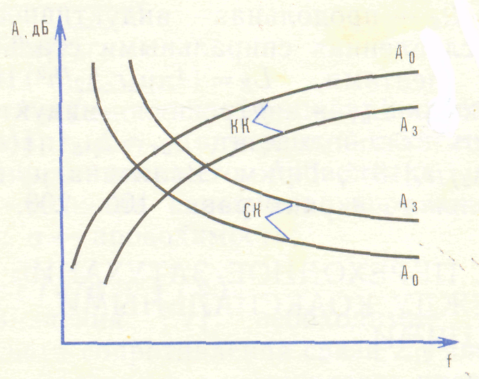
Частотная зависимость переходного затухания A в коаксиальных и симметричных кабелях различна (рис. 3.21). В симметричных кабелях переходное затухание падает, так как с ростом частоты увеличиваются электромагнитные связи (K12 и M12). В коаксиальных кабелях А растёт, поскольку увеличивается экранирующий эффект внешнего проводника кабеля. С увеличением длины коаксиальной линии переходное затухание изменяется по тому же закону, что и в симметричной линии (см. рис. 3. 10 лекции №5).
transient attenuation
← coaxial cables
← symmetric cables
Frequency
Рис. 3.21.Частотная зависимость переходного затухания в коаксиальных (КК) и
симметричных кабелях (СК)
Fig. 3.21 – Frequency dependence of the transient attenuation in the coaxial (КК) and
symmetric (СК) cables
Frequency dependence of the transient attenuation A in the coaxial and symmetric cables is different (fig. 3.21). In symmetric cables the transient attenuation decreases, because the electromagnetic couplings (K12 and M12) increase with the increase of frequency. In the coaxial cables value A increase, since the screening effect of the cable external conductor increases. With the increase of the coaxial line length the transient attenuation is changed on the same law, as the low in the symmetric line (look at Fig. 3.1 of the lecture #5).
Лекция № 10
Lecture # 10
3.10. НОРМЫ ПЕРЕХОДНЫХ ЗАТУХАНИЙ МЕЖДУ ЦЕПЯМИ
3.10. standardS OF THE transient attenuation BETWEEN CIRCUITS
a45
Помехи по своему действию подразделяются на шумы и переходные разговоры.
Напряжение шумов маскирует слабые составляющие разговорной речи, снижая тем самым диапазон полезного сигнала.
Помехи бывают следующих типов:
- тепловые, обусловленные дробовым эффектом ламп и хаотическим тепловым движением электронов в транзисторах и жилах кабеля;
- нелинейные шумы, возникающие вследствие нелинейных характеристик аппаратуры и устройств группового тракта;
- линейные переходы, обусловленные электромагнитным влиянием между цепями связи.
По действующим нормам ССЭМСЭ (Сектор стандартизации электросвязи Международного союза электросвязи), называемым «Рекомендации», величина всех помех на эталонной цепи длиной 2500 км в точке с нулевым относительным уровнем не должна превышать по мощности 10 nВт. Это соответствует напряжению шумов 1,1 мВ. Причём, 2,5 нВт отводится на долю аппаратуры оконечных и транзитных устройств, а остальные 7,5 нВт – на линию с усилителем (в среднем 3 пВт на 1 км цепи). Величины помех, отводимые на линейный тракт, по-разному подразделяются для симметричных и коаксиальных цепей (см. таблицу 3.2):
Таблица 3.2
|
Симметричный кабель |
Коаксиальный кабель |
Тепловые шумы, % |
25 |
50 |
Нелинейные шумы, % |
25 |
50 |
Линейные переходы, % |
50 |
– |
The interference on the action subdivided into noises and crosstalk. Noise voltage masks weak components of conversation, reducing thereby the range of a useful signal.
The interference take place the following types:
- thermal, stipulated by the shot effect of lamps and chaotic thermal motion of the electrons in transistors and cable cores;
- the nonlinear noises arising from nonlinear characteristics of equipment and control unit channel;
- linear junctions, stipulated by the electromagnetic influence between communication circuits.
From the operating norms of ITU-T (International Telecommunication Union - Telecommunication sector), which named «Recommendations», the value of all noises on the standard circuit long 2500 kilometers in the point with a zero relative level must not exceed on the power10 nW. It corresponds to the voltage of noises 1.1 mV. Besides, 2.5 nW is taken on the equipment share of the terminal and transit devices, and other 7.5 nW – for the line with amplifier (on the average 3 pW for 1 kilometer of circuit). The value of noises, taken on a linear highway, differently subdivides for symmetric and coaxial cables (look at the Table 3.2):
Table 3.2
|
Symmetrical cable |
Coaxial cable |
Thermal noise, % |
25 |
50 |
Nonlinear noise, % |
25 |
50 |
Linear junctions , % |
50 |
– |
a46
Поскольку коаксиальные кабели обладают высокими экранирующими свойствами, линейные переходы у них должны отсутствовать. Однако величины переходных затуханий и защищенность, как на коаксиальные кабели, так и на другие типы линий нормируются. Исходя из допустимой величины шумов в цепях связи 1,1 мВ величина защищённости цепей от переходного разговора должна быть не менее 54,7 дБ.
Для двухпроводных цепей воздушных линий связи допускается защищённость 50,4 дБ. Соответственно этим величинам нормируются значения переходного затухания и защищённости на усилительный участок.
Токи помех с
усилительных участков складываются,
поэтому защищённость на один участок
должна быть увеличена во столько раз,
сколько усилительных участков имеет
данная магистраль. Однако для токов
помех применяется геометрический закон
сложения, поэтому величина защищённости
уменьшается не в N раз, а
в
 (см.
рис. 3.7 лекции №3). Таким образом, на
ближнем и дальнем концах усилительного
участка необходимо иметь защищённость
(см.
рис. 3.7 лекции №3). Таким образом, на
ближнем и дальнем концах усилительного
участка необходимо иметь защищённость
 (дБ), где N – число
усилительных участков.
(дБ), где N – число
усилительных участков.
Нормы переходного
затухания и защищённости воздушных и
кабельных линий определяются по
различной методике. Для воздушных линий
защищённость нормируется на эталонную
линию (2500 км), поэтому её величину
необходимо пересчитывать на один
усилительный участок. Для кабельных
линий защищённость нормируется
непосредственно на один усилительный
участок (исходя из защищённости на
эталонную линию). Во всех случаях следует
иметь в виду, что с увеличением длины
линии влияние увеличивается и защищённость
снижается по закону
 [дБ]. Здесь
 и
и -
соответственно нормированная и
определяемая защищённость; l
и lx
– длины участков, на которых нормируется
и определяется защищённость.
-
соответственно нормированная и
определяемая защищённость; l
и lx
– длины участков, на которых нормируется
и определяется защищённость.
As long as coaxial cables have the high screening properties, linear junctions in them must be absent. However values of the transient attenuation and protectability both on coaxial cables and on other types of lines are normalized. Coming from the permissible value of noises in communication circuit of 1,1 mV, the value protectability of circuits from the crosstalk must be not less than 54,7 dB.
For two-wire circuits of the airlines coupling protectability 50,4 dB is supposed.
According to these values attenuation and protectability are normalized for the repeater section. The noise currents from repeater sections are added; therefore the protectability for one should be increased by one site in so much time, how many repeater sections the given pipe-line has. However for the noise currents the geometrical law of addition is used, therefore the value protectability is decreases not in N time, and in time (look at Fig. 3.7 of the lecture #3). Thus, on the near end and far end of the repeater sections it is necessary to have protectability (dB), where N is quantity of repeater sections.
Norms for the transient attenuation and protectability of the air and cable lines are defined on a different methodology. For the airlines the protectability is normalized for the standard line (2500 kilometers), therefore the value of the protectability must be counted for the one repeater section.
For cable lines the protectability is normalized directly for the one repeater section (coming from protectability for the standard line). It is necessary to mean in all cases that with the increase of length of line the influence increases and protectability is decreases by law, [dB].
Here is normalized protectability is defined protectability; l is normalized lengths of line and lx is lengths of line where protectability is defined.
a47
Для воздушных линий связи защищённость на длине усилительного участка:
 [дБ]
(3.51)
[дБ]
(3.51)
Переходные затухания на дальнем и ближнем концах усилительного участка будет соответственно:
 [дБ]
(3.52)
[дБ]
(3.52)
 ,
(3.53)
,
(3.53)
где p – коэффициент отражения, принимаемый для ВЧ телефонирования p = 0,1
Для цепей из стальных проводов защищённость Aз = 46,9 дБ.
Для ВЧ цепей симметричных кабелей нормируются:
Защищённость на длине усилительного участка, дБ….. Переходное затухание на дальнем конце, дБ………….. Переходное затухание на ближнем конце для двухкабельной системы, дБ………………………… Переходное затухание на ближнем конце при однокабельной системы, дБ………………………... |
73,8 (допускается 10% значений 71 dB)
73,8 +
60,8
73,8 + |

Для НЧ симметричных кабелей нормируются:
|
Двухпроводный режим |
Однопроводный режим |
Защищённость на длине усилительного участка, dB… |
60,7 |
65,1 |
Переходное затухание на дальнем конце, дБ………… |
60,8 + |
65,1 + |
Переходное затухание на ближнем конце, дБ………... |
60,8 + |
65,1 + |
Для коаксиальных кабелей нормируются:
|
ra/rb = 2,6/9,5 мм |
ra/rb = 1,2/4,6 мм |
Защищённость на длине усилительного участка, dB.. |
110 |
90,3 |
Переходное затухание на дальнем конце, дБ……… |
110 + |
90,3 + |
Переходное затухание на ближнем конце, дБ……... |
110 + |
90,3 + |
For the airlines the protectability on the length of the repeater section is
 [dB]
(3.51)
[dB]
(3.51)
The transient attenuation on the far end and near end of the repeater section will be:

 [dB]
(3.52)
[dB]
(3.52)
 ,
(3.53)
,
(3.53)
where р is the reflection coefficient accepted for the high frequency (HF) telephones 0,1.
For the steel circuits the protectability Aз = 46,9 dB.
For the HF circuits of the symmetric cable next parameters are normalized:
Protectability on the repeater sections, dB…….…………….. Transient attenuation on far end, dB……………………..… Transient attenuation on near end for 2-cable system, dB…. Transient attenuation on near end for 1-cable system, dB…. |
73,8 (allowed 10% value 71 dB) 73,8 + 60,8 73,8 + |
For the low frequency (LF) circuits of the symmetric cable next parameters are normalized:
|
2- wire operating regime |
4- wire operating regime |
Protectability on the repeater sections, dB |
60,7 |
65,1 |
Transient attenuation on far end, dB |
60,8 + |
65,1 + |
Transient attenuation on near end, dB |
60,8 + |
65,1 + |
For the coaxial cable next parameters are normalized
|
ra/rb = 2,6/9,5 мм |
ra/rb = 1,2/4,6 мм |
Protectability on the repeater sections, dB….. |
110 |
90,3 |
Transient attenuation on far end, dB………… |
110 + |
90,3 + |
Transient attenuation on near end, dB………. |
110 + |
90,3 + |