

Торсионные поля и информационные взаимодействия – 2016
.pdf150mm is connected. The outside end of the secondary coil is connected to a ground line, which is the link of the transmitter and receiver.
The primary coil is printed under the printed circuit board with wider copper wire. The primary coil is connected directly to the output of the RF driver circuit. At the exact resonance frequency, there will be low impedance at the primary coil of the transmitter. So the RF driver should be a special one, this will be discussed later.
The two coils of the Phase-Conjugate-Resonator are in Figure 4.
Figure4. The two Tesla coils in Phase-Conjugate-Resonator
The signal generator and the RF amplifier circuit are also needed for driving the transmitter of the Phase-Conjugate-Resonator. The signal generator is DDS type,frequency range is 0-8 Mhz, the output impedance is standard 50 Ohms, which is suitable for the input impedance of RF amplifier. The RF amplifier is a kind of class AB amplifier, whose bandwidth is 3-30 Mhz and designed power is 45 watts. But the output impedance of the RF amplifier should not be 50 Ohms because of the low impedance of the primary coil of transmitter coil. So the impedance of primary coil and the output impedance of RF amplifier should be matched.
As to the adjustment of the Tesla Phase-Conjugate-Resonator, we should pay attention to what N.Tesla said in 1927:
"The mode of propagating the currents from the transmitter through the terrestrial globe is most extraordinary considering the speed of the electrification of the surface. The wave starts with a theoretically infinite speed, slowing down first very quickly and afterwards at a lesser rate ... The mean surface speed is thus about 471,200 kilometers per second -- fifty seven percent greater than that of the so-called Hertz waves -- which should propagate with the velocity of light if they exist ...
in the system I have devised only force is conveyed to all points of the earth, the energy itself travelling in definite paths determined beforehand. Perhaps the most wonderful feature is that the energy reaches the receiver without the slightest dispersion, so that an incomparably greater amount is collected than is possible by radiations [4]."
Prof.K.Meyl also talked about the transmission of scalar wave with 1.5 times the speed of light [5]. In this work, there are two frequencies, one is the frequency of LC resonance, other one is the frequency of Phase-Conjugate-Resonance. According to 1/4 wavelength theory, the wavelength would not change with the same coil, so the ratio of speeds would be equal to the ratio of frequencies. In this work, the frequency of LC resonance is 2.65 Mhz, and the frequency of Phase- Conjugate-Resonance is 4.17 Mhz, so the ratio of these two frequencies is about 1.57 .
261
That's the whole configuration of the Phase-Conjugate-Resonator, corresponding to the condition of scalar wave.
2.2. Methodology
There are many methods for detecting torsion field, see [6]. In this work, the torsion balance consisting of a wooden frame is chosen to detect the torsion field generated by the dual Tesla coil system.
The torsion balance method is very sensitive and it can be rotated by torsion field directly. In [7, 8], this method was used by V.Zamsha and V.Shkatov in their telekinetic experiment with two photos at distance of about 8000 kilometers. There was obvious rotation of wooden frame after the palm was near the photo of wooden frame remotely.The video of this experiment is in [9].
There are also many experiments showing this method by V.Zamsha in [10, 11, 12]. In these experiments, the wooden frame was rotated by the photo of crystal, the hands, the photo of human and the torsion field generator.
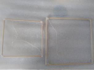
Of course this method is also verified by other scientists and is also easy-built. So it's chosen in this work. The wooden frames used in experiments are in figure5. There are different sizes of them, the side length of left frame is 148mm and the side length of right frame is 206mm.
Figure5. The wooden frames used in experiments
2.3. The full configuration of hardware
In this part, all kinds of the hardware are combined to a whole system to conduct the experiment. The full configuration is in Figure6.
In this configuration, the transmitter is put on the table. The receiver is put into a closed hardboard box on the ground. The wooden frame is suspended at the top of the stainless steel ball antenna by a very thin line.
262
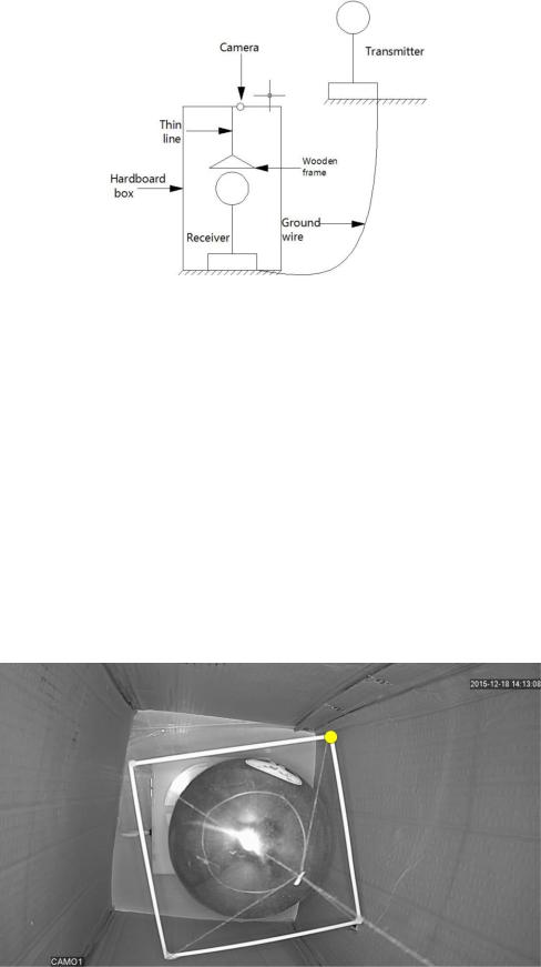
Figure6. The full configuration of experiments
The other side of this thin line is connected at the center of the top cover of box. There is a hole next to the center at the top cover of box, it's used to place a WIFI camera here. Then the scene in the box can be watched in real time at any place.
3. Experimental process
In this section, the experiment process will be described in detail. There are two representative and independent experiments in this part. The torsion balance consisting of the wooden frame is used in the experiments.
In the first experiment, the wooden frame whose side length is 148mm was used. The wooden frame was put into the hardboard box hung by a very thin line. Then the hardboard box was closed and the author used the WIFI camera to watch the inside of the box on the computer a few meters away. Before the beginning of this experiment, the author let the wooden frame be relaxed until it was static. The relax time was more than 24 hours, and the screen on the computer showed that the wooden frame was almost static. The static wooden frame could not rotate in a closed box if there was no extern force. The process is in block figure7 and the video [13].
263
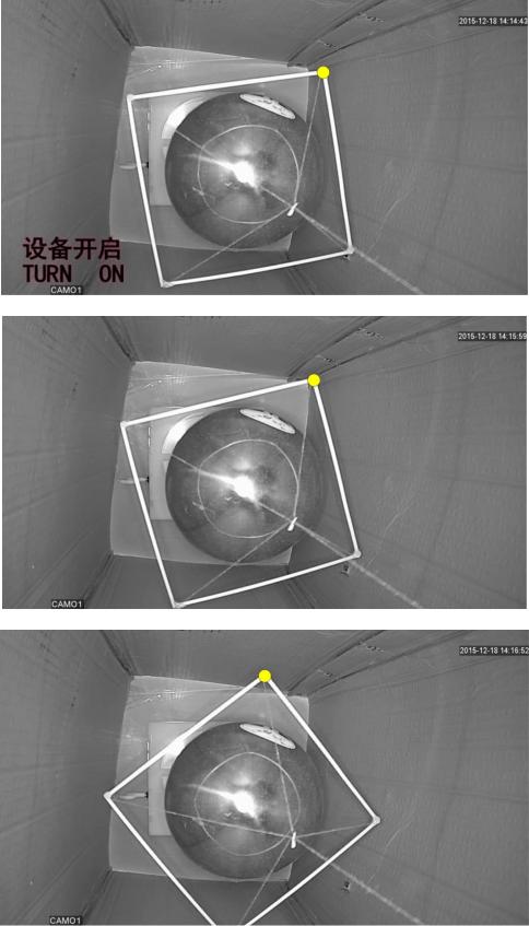
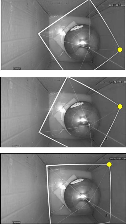
Block figure7. Sample positions of the wooden frame in the first experiment, one of the corners was marked using a yellow circle.
As we can see from the video, there is regular movement of the wooden frame. The direction of rotation was counter clockwise from the camera. At first stage, the angular acceleration of wooden frame was the largest at the beginning of the movement, then the acceleration would become smaller and smaller because the torque force of the thin line whose direction was opposite
264
to the direction of torsion field force would become larger and larger. And the angular speed of wooden frame would be larger and larger. At second stage, the angular speed of wooden frame became largest when the torque force of the thin line was equal to the torsion field force generated by the dual Tesla coil. Then the angular acceleration would change its direction and became larger and larger because the torsion field force didn't change but the torque force of the thin line became larger and larger as the wooden frame rotated. The angular speed of wooden frame would be smaller and smaller until the wooden frame stopped.
Then the wooden frame would be back and forth for several times as the law said above. At last, the wooden frame would be static in a position, where the torque force of the thin line was equal to the torsion field force. This position would be between the original position and the maximum angular position of the wooden frame. In fact, the wooden frame would back to the original position after turned off the device. But this process was not in this video. It will be discussed in the second experiment.
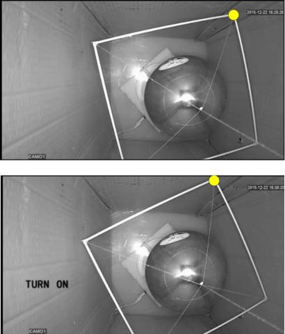
In the second experiment, the wooden frame whose side length is 206mm was used. This larger wooden frame was in the same position as in the first experiment. Other configuration was also the same. But in the second experiment, the author didn't wait until the wooden frame was static, because the wooden frame was more sensitive with larger size. It was very difficult to let the wooden frame be absolutely static. So the second experiment began when the wooden frame was oscillating back and forth in a small scale. If the wooden frame rotated in a large scale after turning on the device, it also could show some significant results. The process is in block figure8 and the video [14].
265

266
Block figure8. Sample positions of the wooden frame in the second experiment, one of the corners was marked using a yellow circle.
The video is 4X speed faster than the normal speed of the original video, because the original video is too long. As we can see, the sample positions are also more than the first experiment, because the movement back to the original position is also recorded in this video.
In the second experiment, there was also regular movement of wooden frame. But there was obvious difference between the first experiment and the second experiment. The direction of rotation was clockwise from the camera. Before the beginning of the second experiment, the wooden frame was not static but it was already oscillating back and forth in a small scale. After turning on the device, the wooden frame began to rotate just like the law in first experiment. The total path of the wooden frame was nearly half a circle. It was a obvious result driving by the torsion field force.
267
There was also a more complete movement process in the second experiment compared with the first one. The process back to the original position was recorded too after turning off the device. As we can see from block figure8, after turning off the device, the wooden frame began to rotate in counter clockwise. Because there was no torsion field force in this time, there was only torque force of the thin line itself in this time. So this force would drive the wooden frame to the original position before the beginning of the experiment.
4. Analysis of results
The results above can be replicated in other author's experiments. The wooden frame whose side length is 148mm rotates in counter clockwise from the camera but the one whose side length is 206mm rotates in clockwise from the camera.
There is regular movement in both of these two experiments, it's obvious that it can't be the random factors leading to the movement of wooden frame.
4.1. The dual vortex structure
Because the two wooden frames are in the same position at the top of the antenna of receiver coil in dual Tesla coil system,just the side length of these two wooden frames is different. So we can move the two wooden frames in one plane in figure9 to analyze.
Figure9. Two wooden frames in one plane from the camera
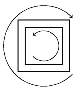
As we can see in figure9, only the side length of two wooden frames is different, other conditions are all the same in these two experiments. But there are two kinds of torsion field including left-handed and right-handed are detected in dual Tesla coil system. It seems that there is a dual vortex structure in scalar wave.
As everyone knows, there is dual vortex phenomena in fluid mechanics. Leonardo da Vinci had observed in liquids the two basic types of vortices in duality:"one of these vortices moves slower at the center than it does at its perimeter and the other moves faster at its center than it does along the perimeter [15]."
And according to Prof.K.Meyl's scalar wave theory, there are two basic types of vortices too. One is the current vortex which has the property of expansion and the other one is the potential vortex which has the property of concentration found by Prof.K.Meyl.
The tornado is a kind of typical phenomena of dual vortex. It consists of expanding vortex from inside and counter vortex contracting from outside. From the results of this work, the dual vortex structure is also detected using two wooden frames with different sizes. So there is the "electromagnetic tornado" in dual Tesla coil system, the author thinks it's a basic structure for
268
wireless energy transmission.
4.2. Scalar wave consists of non-stationary spinning
In one of the Dr.M.Krinker's works, the 14g disk suspended inside the double quadrupole spinner turned for about 10 degrees. The spinning in the quadrupole spinner was modulated in amplitude specially, so the non-stationary spinning was generated to drive the disk [16].
Non-stationary spinning is very important to generate the mechanical torque which can rotate the wooden frame. According to the model of scalar wave in Figure3, there are many vortices with different diameters perpendicular with the direction of transmission. These vortices follow the Lorenz Transformation. When the diameter of vortex is the maximum, then the angular speed is the minimum at the anti-node; when the diameter of vortex is the minimum, then the angular speed is the maximum at the node. The angular speed of the vortices between anti-node and node are different and the scalar wave is a kind of longitudinal wave with the property of oscillation, so the vortices of scalar wave are a kind of non-stationary spinning.
5. Conclusions and further developments
In this work, author mainly did many experiments using the torsion balance consisting of wooden frame. Two typical experiments are chosen to be analyzed. To be honest, the second experiment is not designed intentionally. Author just wants to improve the sensitivity using the larger wooden frame at first, but the opposite direction is detected. Author believes that the size of dual vortex structure generated by dual Tesla coil system can be changed with different power.
Some conclusions:
The nature of scalar wave is torsion field.
There are two kinds of torsion field including left-handed and right-handed in the resonant dual Tesla coil system. They are combined to become a tornado structure.
The vortices of scalar wave are a kind of non-stationary spinning.
The torsion balance consisting of wooden frame is a sensitive method to detect the torque generated by the torsion field.
Of course this work is just a beginning, further exploration and experiments are needed. For example, testing with different driving power for Tesla scalar system; testing with different position of wooden frame; testing the transmitter coil and receiver coil of Tesla scalar system simultaneously; testing Tesla scalar system for non-local effects and so on.
6. Acknowledgment
Author would like to thank V.Shkatov and V.Zamsha, who wrote the book called "Torsion Field and Interstellar Communication". Author got Mr.V.Zamsha's permission to translate this book into a Chinese version and spread it for free. There is no this book, then there is no this work. Author also would like to thank Mr.M.Krinker for some discussions and the joint non-local experiments. Further more, author would like to thank Association of Unconventional Science and Cybertronica Research for their translated English version papers and files about torsion field.
7.Reference
[1]Vesperman. Gary. Space travel innovations.
[2]Nikola Tesla. Apparatus for transmission of electrical energy. May 15 1900. US Patent 649,621.
[3]Konstantin Meyl. Dna and cell resonance. INDEL G mb H Verlagsabteilkung,
Villingen-Schwenningen,(2ndedn), Germany, 2011.
269
[4]Nikola Tesla. World system of wireless transmission of energy. Telegraph and Telephone Age, 1927.
[5]Konstantin Meyl. Scalar waves: Theory and experiments1. Journal of Scientific Exploration, 15(2):199–205, 2001.
[6]Serge Kernbach. On metrology of systems operating with high penetrating emission. International Journal of Unconventional Science,1(2):76–91, 2013.
[7]Vitaliy Zamsha and Victor Shkatov. Telekinetic experiment with two
photos at distance of about 8,000 kilometers.
[8]Victor Shkatov and Vitaliy Zamsha. Torsion field and interstellar communication. 2015.
[9]Victor Shkatov and Vitaliy Zamsha. https://youtu.be/ld7-hk5xmzq.
[10]Vitaliy Zamsha. https://youtu.be/mm8ih3q-3nq.
[11]Vitaliy Zamsha. https://youtu.be/ucw0hq687ds.
[12]Vitaliy Zamsha. https://youtu.be/e7pivjo–v4.
[13]Gao Peng. https://www.youtube.com/watch?v=uosaexjbsgm.
[14]Gao Peng. https://www.youtube.com/watch?v=kvkbocxkhxe.
[15]Konstantin. Meyl. About vortex physics and vortex losses. Journal of
Vortex Science and Technology, Ashdin Publishing, Vol. 1 (2012), (Article ID 235563):10 pages doi:10.4303/jvst/235563, 2012.
[16] Mark Krinker. Some physical aspects of artificial and natural field gyroscopes. relation to atmospheric phenomena and geo-pathogenic zones.
2014.
ПОПЫТКИ ОБНАРУЖИТЬ ТОРСИОННЫЙ ХАРАКТЕР ПОЛЯ СКАЛЯРНОЙ ВОЛНЫ, ГЕНЕРИРУЕМОЙ ДВОЙНОЙ СИСТЕМОЙ КАТУШЕК ТЕСЛЫ
Gao Peng
The Scalar Wave Technology Research Web, Китай Лаборатория Beijing Wellan Century Co., Ltd
gpufo@outlook.com
Впервые скалярные волны были обнаружены Николой Тесла и использованы в его экспериментах по беспроводной передаче энергии. Проф. К. Мэйл расширил уравнения Максвелла и нашёл скалярные волны как недостающую их часть. Теория скалярных волн, предложенная проф. К. Мэйлом, указывает, что скалярные волны имеют торсионный характер. Данная работа пытается обнаружить торсионный характер скалярных волн, генерируемых двойной системой катушек Теслы, используя крутильные весы в виде деревянной рамки. Результат положительный: обнаружены два вида кручения, левое и правое в двойной системе катушек Теслы.
270