

Execution of the laboratory work
1. Study the theoretical principles of using PN for modeling of digital systems.
2. Present home-work results.
3. Input into your computer the description of the input and output PN matrices of an on-board computer.
4. Calculate the compatibility matrix using your computer.
5. Input the initial marking of the PN into your computer and define possible functional states of the on-board computer using a space of reachable markings and a table of PN semantic description.
Contents of the Experimentation Paper
1. Home-work results.
2. An input, an output and a compatibility matrices.
3. A space of reachable markings.
4. Conclusions (analysis of the functional states of an on-board computer).
Home work
1. Study the PN of an on-board computer and the semantic description of the net. For the PN make up the following:
• a matrix equation of the input matrix;
• a matrix equation of the output matrix;
• a matrix equation of the compatibility matrix.
2. Make up a program for determination of the space of reachable markings for a given PN which enables the following:
• computing a compatibility matrix using the input and output matrices;
• computing a possible PN marking using a given initial marking.
3. Make up a program for outputting the results of modeling.
4. The programs are to be executed using a high-level language.
Questions for the Self-Testing
1. Why doesn’t a PN marking have negative values?
2. How are the PN tools used for modeling of logic formulas?
3. How can a compatibility matrix be determined?
MODULE 3
Laboratory work 3.1
DATA CONVERSION FROM BINARY TO DIGITAL LOGARITHMIC FORM. DIGITAL-LOGARITHMIC ARITHMETIC
Aim of the work: The aim of the work is to study algorithms for conversion of binary numbers into digital logarithmic (DL) representation and get acquainted with basic procedures of DL arithmetic.
Basic Principles
Let
an n-capacity
binary number A
be represented in a fixed-point format:
![]() where
is the radix.
where
is the radix.
Each digit ai equal to non-zero ( ) may be represented as a position digit number Ni. Thus the binary number A can be represented by an array of non-zero digit numbers:
where Ni is the number of non-zero digits ( ).
The use of DL representation makes it possible to build a common structure for formats with floating points and fixed points. For each number of non-zero digits the representation capacity may be increased by 1 bit; the value of the order is added to each number if this order is the power index of 2. Consequently, the structure of a generalized representation has the form:
SignA |
Q |
SignN1 |
N1+p |
SignN2 |
N2+p |
… |
SignNn |
Nn+p. |
The conversion from binary representation to the form where each non-zero digit is represented by its number is uniquely determined and realized without additional functional transforms. A substitution operation is performed with each non-zero digit.
The conversion of binary numbers into DL forms may be performed by two methods. The first method lies in finding the difference between the number and the power indices of two and substituting these indices into the DL array if the difference is positive. If x - 2i 0, then the value of the variable i is included as an element of elements of the resultant array of DL digits, and the value of x is decreased by 2i. The process of finding the significant digits of the result continues until x becomes zero or the array size exceeds the limitations or precision determined by the conditions of the problem.
The second method lies in logical addition of the digits of a binary number and the power indices of two. If the result is positive, then the number of the binary digit is written to the DL array. The process continues until all the binary digit numbers have been conver-ted. This process is controlled by the size of the binary number in bits.
T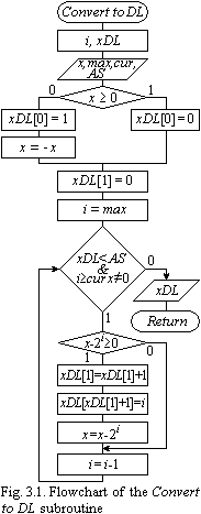 he
flowchart of the Convert
to DL
subroutine realizing the algorithm of number conversion from the
binary number system to DL representation is depicted in Fig. 3.1.
he
flowchart of the Convert
to DL
subroutine realizing the algorithm of number conversion from the
binary number system to DL representation is depicted in Fig. 3.1.
The variables used in the algorithm are: x is the binary number used to be converted; xDl is an array of integer numbers (DL representation of the number x); max, cur are constants defining accordingly the range of data variation and the precision of their representation; AS is the limitation on the size of the xDL array; and i is an auxiliary variable.
The sign of x is determined at the first step of the algorithm. “1” is written as the zeroth element of the DL array if x is negative, and “0” otherwise. Besides, if x is negative, its sign needs to be changed to the opposite, since transformations are done on the all subsequent absolute value of the number. According to DL data representation, the next array element after the sign should be the element with the number Q, i.e., the number of significant digits of x. That’s why this element is zeroized at the beginning of the conversion. The value of max is assigned to the variable i. The significant digits of the result are determined by substitution. If x 2i, then the value of i is included as an element of the resultant array xDL, and the value of x is decreased by 2i. The process of finding the significant digits of the result continues until x becomes zero or the size of the array exceeds the limitation AS or the value of i becomes less than the specified precision cur.
Data conversion to DL code with structural support is performed as writing of appropriate codes to the positions of nonzero digits:
X2=+ |
1 |
0 |
0 |
1 |
0 |
1 |
0 |
1 |
|
|
|
|
|
|
|
|
|
|
111. |
***. |
***. |
100. |
***. |
010. |
***. |
000. |
XDL=0,4,7.4.2.0.
Common procedures used in operations of DL arithmetic, as opposed to the binary one, are data sorting and collecting terms.
An example of the algorithm of array sorting (SORT) in decreasing order of its elements is depicted in Fig. 3.2, where the following notations are used: S is the initial array of a DL number; i, j are the cycle indices; and t is sorting parameter.
An example of the algorithm collecting terms (COL) is depicted in Fig. 3.3, where the following notations are used: S is the initial array of a DL number; G is the resultant array; i is the cycle index; and x is an auxiliary variable for finding the order and total number of elements in the array G.
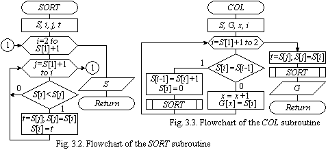
The SORT and COL subroutines will be used in the study of arithmetic operations in DL data representation in the following laboratory works.