

1.3.3 Decoding of the nonsystematic convolutional codes
Nonsystematic convolutional codes are specified by polynomials in an octal notation usually, and for construction of the coder it is necessary to convert polynomials in binary form.
Let's consider the elementary nonsystematic code (7, 5). For reception of generator polynomials we will convert figures in binary and polynomial notations:
G(1) = 78 = 1112 D2 + D + 1,
G(2) = 58 = 1012 D2 + 1.
 The
flow diagram of the coder corresponding to polynomials G(1)
and G(2),
is resulted in fig. 1.8a.
The state diagram for this coder is shown in figure 1.8b.
The
flow diagram of the coder corresponding to polynomials G(1)
and G(2),
is resulted in fig. 1.8a.
The state diagram for this coder is shown in figure 1.8b.
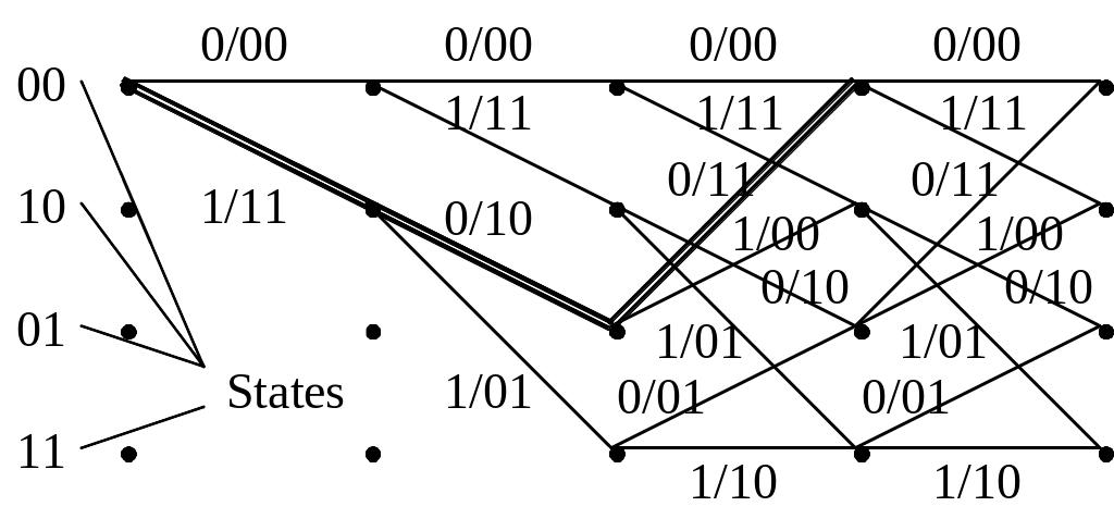
Figure 1.8 – Flow (a) and state (b) diagram of the coder (7,5)
Convolutional coder as the final automatic machine with memory is described by the state diagram. Internal states of the coder are the symbols containing in (K – 1) register cells (beginning from a coder input). The coder in fig. 1.8a can be in one of four states S1S2 = (00, 10, 11, 01), as K = 3. The diagram represents the directed graph which contains all states and describes possible transitions from one state to another, and also symbols of inputs/outputs of the coder, accompanying these transitions. Coder states are shown in circles; arrows show the possible transitions. Symbols about arrows are shown coder input/output a/b(1)b(2), corresponding to each transition.
The development of the state diagram in time forms the trellis diagram (fig. 1.9). On a trellis the states are shown by the trellis points, transitions connect them by the lines. The trellis diagram represents all resolved paths on which the coder can move ahead at coding.
To determine free code distance of CvC (7,5) we have to encode the single influence of kind ei = 1 0 0 0 0 0 0 . . . 0 by the formula (1.22):
v = 11 10 11 00 00 00 00…
W(v) = 5, so df = 5.
The way of the coding of such sequence is shown in the fig. 1.9 by double branches.
Figure 1.9 – Trellis diagram of the coder (7,5)
Constraint length of such code and the amount of informative bits in the limits of CL are
Na = n0 (K + 1) = 2 (2 + 1) = 6, Ka = K + 1 = 3.
As the amount of inputs of the coder (7, 5) k0 = 1, and the amount of the outputs n0 = 2, relative information transfer rate and redundancy are
R = k0/n0 = 1/2, ρ = 1 – R = 1/2.
 Nonsystematic
codes can be decoded by probabilistic algorithms of decoding, i.e.
sequential decoding algorithm (SDA) and the Viterbi algorithm (VA).
Nonsystematic
codes can be decoded by probabilistic algorithms of decoding, i.e.
sequential decoding algorithm (SDA) and the Viterbi algorithm (VA).
The idea of the sequential decoding consists of that a path must proceed only on the path tree which looks like most probable. A path is a certain sequence of combinations of the coder output (on a transmission), corresponding to the certain informative sequence acting on the entrance of the coder. Totality of such output sequences forms this tree, where every branch corresponds to the certain sequence on the output of the coder.
Viterbi algorithm is modified variant of the sequential decoding algorithm, which differs from it on some positions:
the search of optimal path is realized on a few paths (branches);
the search of optimal path is realized on a trellis, which is got from the path tree by shorting of the similar (identical) states of knots and branches;
the specific number of operations, necessary for decoding of code sequences corresponding to single bit, does not depend on the number of the received error symbols and is permanent.
Decoding
on Viterbi
algorithm
is tracing on a code trellis of a path with maximum posterior
probability. At decoding choose such sequence of branches
![]() ,
which provides a sum minimum
,
which provides a sum minimum
PM
=![]() , (1.29)
, (1.29)
where
![]() – input
sequence of the decoder;
– input
sequence of the decoder;
![]() – set of code branches estimation.
– set of code branches estimation.
The
expression (1.29) is the
decoded path
metrics
(PM).
The path metrics is the sum of branches metric: PM =![]() ,
where branches
metrics
are
,
where branches
metrics
are
![]() .
In the discrete channel for an estimation of distances use Hamming
metrics.
.
In the discrete channel for an estimation of distances use Hamming
metrics.
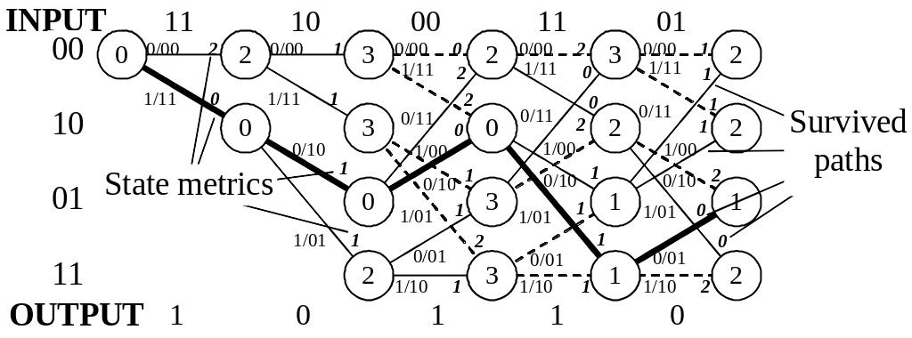
The periodic structure of the trellis diagram essentially simplifies comparison and a choice of paths according to rules (1.29). The amount of states on a trellis is limited, and two at random enough long paths have, as a rule, the common states. Sections of the paths entering these states are necessary to compare and choose a path with the least (minimum) metrics. Such path is surviving. According to Viterbi algorithm comparison and cutting of paths sections make periodically on each step of decoding. We will consider decoding (7, 5) which symbols are transferred on the discrete channel. In this case the branches metrics BM is equal to Hamming distance between a bit set b(1)b(2) on the decoder input and a bit set v(1)v(2), corresponding to the given branch on the trellis diagram. If b(1)b(2) = 01, possible values of BM for a code (7, 5) with a trellis represented on fig. 1.9, will be: BM(00) = 1, BM(01) = 0, BM(11) = 1 and BM(10) = 2. The path metrics is the sum of metrics of the branches forming some path on the trellis diagram. The state metrics SM is equal to PM which comes to an end in the given state.
 In
fig. 1.10 development of decoding process for code (7, 5) is shown.
On a decoder input pairs of symbols from the channel b(1)b(2)
=
11 10 00 11 01 enter
...
Figures about branches designate branches metrics; figures in
circles designate state metrics. In the initial moment of time the
decoder is in a state 00 and initial metrics SM(00)
= 0. If from the channel symbols 11 enter, metrics of two branches
leaving this state, BM(00)
= 2 and BM(11)
= 0. As other branches from the state 00 in states 00 and 11 there
are not, metrics of these states are equal to metrics of entering
branches: SM(00)
= 2 and SM(10)
= 0. Similarly on the following step, when from the channel symbols
10 enter. Here BM(00)
= 1, BM(11)
= 1
and
BM(10)
= 0, LM(01)
= 2. States metrics on this step are defined now as the sums of
metrics of entering branches with metrics of the previous states:
SM(00)
= 2 + 1 = 3,
SM(10)
= 2 + 1 = 3, SM(01)
= 0 + 0 = 0, SM(11)
= 0 + 2 = 2. On this step the development of the trellis diagram
comes to end.
In
fig. 1.10 development of decoding process for code (7, 5) is shown.
On a decoder input pairs of symbols from the channel b(1)b(2)
=
11 10 00 11 01 enter
...
Figures about branches designate branches metrics; figures in
circles designate state metrics. In the initial moment of time the
decoder is in a state 00 and initial metrics SM(00)
= 0. If from the channel symbols 11 enter, metrics of two branches
leaving this state, BM(00)
= 2 and BM(11)
= 0. As other branches from the state 00 in states 00 and 11 there
are not, metrics of these states are equal to metrics of entering
branches: SM(00)
= 2 and SM(10)
= 0. Similarly on the following step, when from the channel symbols
10 enter. Here BM(00)
= 1, BM(11)
= 1
and
BM(10)
= 0, LM(01)
= 2. States metrics on this step are defined now as the sums of
metrics of entering branches with metrics of the previous states:
SM(00)
= 2 + 1 = 3,
SM(10)
= 2 + 1 = 3, SM(01)
= 0 + 0 = 0, SM(11)
= 0 + 2 = 2. On this step the development of the trellis diagram
comes to end.
Figure 1.10 – Decoding process for code (7, 5)
Two paths lead to each new state. For example, to the state 00 leads paths from states 00 and 01. The decoder calculates paths metrics as the sums of metrics of the previous states and metrics of entering branches.
Then goes paired comparison of metrics of the paths entering into each state. As a result of comparison the decoder chooses the smaller metrics and it consider as the metrics of the given state for the subsequent step of decoding. The path entering into the given state with the smaller metrics is survived. The paths entering into states with the big metrics, consider torn off. They are shown on the trellis diagram by shaped lines.
If metrics of compared paths are identical, a choice of one of two paths make in a random path. On each step as a result of comparison half of possible paths is rejected and further is not used. Other half forms continuations of paths for a following step of decoding. From each state on a following step there are two variants of paths continuation again. It provides a constancy of the calculations made on each step. The decoder traces a path having the minimum distance from a path which generates the coder on a trellis.
The resulted path with minimal PM = 1 is shown in fig. 1.10 by bold line, the output of the decoder is 1 0 1 1 0.
Decoding of convolutional code can be realized with hard or soft decisions, and on the output decoder we will get hard or soft data. At decoding with a hard decision, every received bit is “0” or “1” depending on that less or more these bits than threshold value. Redundant information, added in the coder, is used in a decoder for determination of errors and, on possibility, their correction. Sought output data of decoder is the corrected code word.