

1.4.3 Turbo codes
Works to improve the serial concatenated coding led to the construction of the new method of concatenated coding – parallel concatenated codes, which are called turbo codes in 1993 by Claude Berrou and other scientists. These codes can provide a characteristic of the communication channel with the noise, approaching the theoretical Shannon limit.
Turbo code is a systematic code in which the check group is made of check bitsб generated by the two encoders of recursive systematic convolutional codes (RSC), and information sequence enters the encoder of first RSC (RSC1) directly, and in the second encoder of RSC (RSC2) through pseudorandom interleaving device.
In recursive systematic convolutional codes previously encoded information bits are continually fed back to the encoder’s input. A binary rate 1/2 RSC code is obtained from a nonsystematic convolutional code by using a feedback loop, and setting one of the two outputs b(1) or b(2) equal to input a. Figure 1.14a illustrates an example of such an RSC code with K = 3, obtained from CvC (7, 5), and figure 1.14b illustrates trellis diagram for this code.
F igure
1.14 – Flow (a)
and
trellis (b)
diagram of the RSC coder (1, 7/5)
igure
1.14 – Flow (a)
and
trellis (b)
diagram of the RSC coder (1, 7/5)
Comparing figures 1.9 and 1.14b, will see that trellis structures of nonsystematic convolutional code (7,5) and recursive systematic convolutional code (1, 7/5) are identical with respect to state transitions and their corresponding output bits. However, the two output sequences do not correspond to the same input sequence.
 Consider
the parallel concatenation of two RSC encoders of the type shown in
fig. 1.14a.
Good turbo codes have been constructed from component codes having
short constraint lengths (K
= 3 to 5). An example of such a turbo coder with code rate 1/3 is
shown in fig. 1.15. There is no limit to the number of coders that
may be concatenated, and, in general, the component codes need not
be identical with regard to constraint length and rate.
Consider
the parallel concatenation of two RSC encoders of the type shown in
fig. 1.14a.
Good turbo codes have been constructed from component codes having
short constraint lengths (K
= 3 to 5). An example of such a turbo coder with code rate 1/3 is
shown in fig. 1.15. There is no limit to the number of coders that
may be concatenated, and, in general, the component codes need not
be identical with regard to constraint length and rate.
Figure 1.15 – Flow diagram of turbo code with component RSC (1, 7/5)
The turbo coder in fig. 1.15 produces code words from each of two component coders. The weight distribution for code words out of this parallel concatenation depends on how the code words from one of the component coders are combined with code words from the another coder.
If the component coders are not recursive, the unit weight input sequence (0 0 … 0 0 1 0 0 … 0 0) will always generate a low weight code word at the input of a second encoder for any interleaver design. In other words, the interleaver would not influence the output code word weight distribution if the component codes were not recursive. However, if the component codes are recursive, a weight-1 input sequence generates an infinite impulse response (infinite-weight output).
The cause of the phenomenal error-rate performance of turbo codes lies in the combination of the following properties:
1) Strong weight dependence of RSC output sequence from the input information sequence, i.e., on the order of zeros and units in it;
2) Using of interleaver to change the type of the input sequence supplied to the coder inputs of composite RSC.
The first purpose of the interleaver is construction of a long code. The second purpose is decorrelation of input sequences of the two coders for creating the possibility of suboptimal iterative decoding algorithm based on the exchange of information between the two decoders. If the input sequence of the two decoders are almost uncorrelated, then with high probability, the errors are not corrected can be corrected by one another. And so on.
Decoding algorithms must have a soft output. There are four algorithms with a soft decision, suitable for decoding of turbo codes:
the algorithm of maximum a posteriori probability (MAP);
the logarithm of maximum a posteriori probability (log-MAP);
maximize the logarithm of a posteriori probability (max-log-MAP);
the soft-output Viterbi algorithm (SOVA).
The algorithm MAP is computationally much more complex than the algorithm SOVA. The operations in the algorithm MAP are multiplication and exponentiation, while in the Viterbi algorithm – a simple addition, comparison and selection.
MAP algorithm reduces the probability of erroneous reception of bits, while the Viterbi algorithm minimizes the probability of errors in the chain of the bits. Both algorithms are almost identical when for transmission are used the channels with low-noise characteristics. At a high level of noise the algorithm MAP provides the best transmission characteristics compared with the Viterbi algorithm for iterative decoding.
An iterative turbo decoder is shown in fig. 1.16. The iterative decoder for composite codes consists of two “soft decoders”, outputs of which are separated by interleavers. The component decoders are based on MAP or SOVA algorithm, generating a weighted soft estimate of the input sequence. An iterative algorithm performs information exchange between the two component decoders.
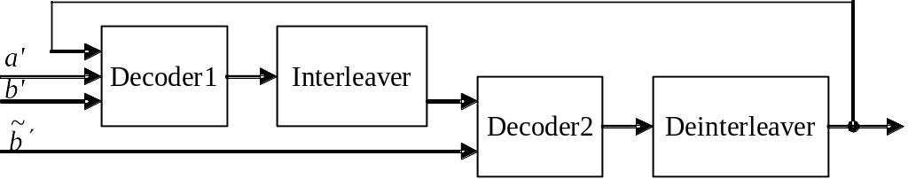
Figure 1.16 – Flow diagram of the iterative decoder
In
the iterative scheme first decoder takes the uncoded input sequence
![]() and
encoded sequence
and
encoded sequence
![]() .
It operates it and gives out a soft decision, which goes through the
interleaver to the second decoder with the accepted information
sequence after the same interleaver
.
It operates it and gives out a soft decision, which goes through the
interleaver to the second decoder with the accepted information
sequence after the same interleaver
![]() ,
as well as a coded sequence of the second encoder
.
The second decoder also makes a soft decision, which can be used by
the first decoder for further errors correction, and so on. After a
few iterations of the decoding unit soft outputs of both decoders
are no longer used for further error correction. In the last stage
the decoder makes a hard decision.
,
as well as a coded sequence of the second encoder
.
The second decoder also makes a soft decision, which can be used by
the first decoder for further errors correction, and so on. After a
few iterations of the decoding unit soft outputs of both decoders
are no longer used for further error correction. In the last stage
the decoder makes a hard decision.