

Phedotikov / 1 / FreeEnergy_27.01.08 / Схемотехнические / Генератор MEG / Build Electrical Over-Unity Devices
.pdfHOW TO BUILD SOLID-STATE ELECTRICAL OVER-UNITY DEVICES
REV. 2.0a
William Alek
INTALEK, INC.
3506-43rd. Place
Highland, IN
46322
CONTACT INFO:
PHONE: 219.924.2742 EMAIL: alekws@intalek.com
(c) INTALEK, INC., 2002
(c) INTALEK, INC., 2002 |
2 |
ABSTRACT
Electrical coil-based devices that use Free Energy or Over-Unity effects require a unique understanding when determining their "correct" operation.
These devices can be placed into three unique categories. The first category are classic coils that use ferromagnetic (iron alloy) core material. These devices typically have a COP (Coefficient Of Performance) less than unity. The second category are coils that use ferromagnetic cores and opposing and/or orthogonal magnetic fields applied by permanent magnets (pms). These devices typically have a COP close to, but NOT greater than unity. The third category are coils that use ferromagnetic cores and/or pms in a special configuration, and have unique operating requirements. These devices have a COP greater than unity.
The purpose of this paper is to present the "hidden" mechanism that is at work in these devices which causes them to produce excess electrical energy.
(c) INTALEK, INC., 2002 |
3 |

THE DEFINITION OF COP
The Coefficient Of Performance, or COP, is a unitless number, and is expressed as a ratio of the energy out divided by the energy in.
EIN |
|
|
|
Coil-Based |
|
|
|
EOUT |
|
|
|
|
|
|
|||
|
|
|
Device |
|
|
|
||
|
|
|
|
|
||||
|
|
|
|
|
|
|
|
|
|
|
|
|
|
|
|
|
|
COP = |
EOUT |
or COP = |
òPOUTdt |
EIN |
òPINdt |
||
|
|
|
FERROMAGNETIC DOMAINS
A ferromagnetic domain of iron alloy core materials can be modeled as an ideal "unity-gain" solenoid. The key words here are unity-gain, meaning that the domains are in electromagnetic equilibrium with the thermal environment. External coils can mutually couple to these domains, thereby increasing its' inductance, and as a consequence, its' energy.
THE MAGNETIC AXIS CAN PIVOT OR ROTATE
 B
B
S
N
B
|
μoH |
I |
|
+ |
S |
|
|
A |
|
- |
N |
|
μoH |
THE POTENTIAL DIFFERENCE IS BOUND WITHIN THE DOMAIN
FERROMAGNETIC |
SOLENOID |
DOMAIN |
MODEL |
(c) INTALEK, INC., 2002 |
4 |
ORTHOGONAL MAGNETIC FIELDS
Magnetic fields are represented as vectors. Adding orthogonal magnetic fields using permanent magnets will " i n c r e a s e t h e p e r m e a b i l i t y μ " o f t h e ferromagnetic core material. As a consequence, the inductance and the energy of the coil increases. The results are a higher COP value.
Y |
|
|
|
|
INCREASING PERMEABILITY: |
||||
|
|
|
|
|
|
|
|
|
|
|
|
|
|
|
|
|
|
|
μXY > μo |
|
|
|
|
|
|
|
|
|
|
|
μXYHXY |
|
|
|
|
|
INCREASES INDUCTANCE: |
||
|
|
|
|
|
|
||||
|
|
|
|
|
|
LXY > LIN |
|||
|
|
|
|
|
BY |
|
|||
|
|
|
|
|
|
|
|||
|
|
|
|
|
|
|
X |
|
INCREASES OUTPUT ENERGY: |
|
|
|
|
|
|
|
|
|
|
0 μoHX |
|
|
|
EXY > EIN |
|||||
|
|
|
|
||||||
|
Y |
|
|
|
|
|
|||
|
|
|
|
|
|
|
|
|
INCREASING PERMEABILITY: |
|
|
BZ |
|
|
|
|
μXYZ > μo |
||
|
|
|
BY |
|
INCREASES INDUCTANCE: |
||||
|
|
|
|
||||||
|
|
|
|
|
|
|
|||
μXYZHXYZ |
|
|
LXYZ > LIN |
||||||
|
|
|
|
||||||
|
|
|
|
|
|
|
|
X |
INCREASES OUTPUT ENERGY: |
|
0 μoHX |
|
|
|
|||||
|
|
|
|
|
|||||
|
|
|
|
|
EXYZ > EIN |
||||
|
|
|
|
|
|
|
|
|
|
Z
(c) INTALEK, INC., 2002 |
5 |

PERFORMANCE METHODS
CATEGORY |
DESCRIPTION |
|
|
1 |
Under-Unity Devices, COP << 1.00 |
|
|
|
Coil/Core - Classic Devices |
|
|
|
Classic use of magnetic fields applied to |
|
ferromagnetic (iron alloy) core materials. |
|
|
2 |
Near-Unity Devices, COP < 1.00 |
|
|
|
Coil/Core/Magnet - SmartPAK POD, POD |
|
|
|
Opposing/orthogonal magnetic fields |
|
applied to ferromagnetic materials. |
|
|
3 |
Over-Unity Devices, COP > 1.00 |
ACoil/Core - SmartPAK ZPOD
E l e c t r o s t r i c t i o n / m a g n e t o s t r i c t i o n phenomena of ferromagnetic materials. Cooling of ferromagnetic material is observed. A "negative" Carnot cycle is occurring within the material
BCoil/Core/Magnet - SmartMEG, MEG, PP
Full flux transfer magnetic core anomaly. This phenomena is related to the nature of flux flowing within the magnetic material.
CCoil/Core/Magnet - H. Kunel, Adams Motor
A variable reluctance control of magnet in a Category 2 Near-Unity device.
(c) INTALEK, INC., 2002 |
6 |
A SYSTEM REQUIREMENT:
THE "SOURCE DIPOLE"
The source dipole, defined as a forced separation of electric charges, serves as a "starting engine" for all these devices. A source dipole may be a battery, a charged capacitor, or any stored-electrical medium. A C A T E G O R Y 1 U n d e r - U n i t y d e v i c e o r a CATEGORY 2 Near-Unity device will eventually deplete, or collapse its' source dipole over time. However, a CATEGORY 3 Over-Unity device can be configured to maintain, or replenish its' dipole.
TWO AND FOUR TERMINAL DEVICES
|
|
|
|
|
|
|
|
EIN |
|
|
|
|
|
|
|
|
|
|
|
|
|
|
|
|
|
|
|
|
|
|
|
||
|
|
|
|
|
|
|
|
|
|
|
|
1 |
|
|||
|
|
|
|
|
|
|
|
|||||||||
Source |
|
|
|
|
|
|
|
|
|
|
|
Coil-Based |
|
|||
|
|
|
|
|
|
|
|
|
|
|
|
|
|
|||
Dipole |
|
|
|
|
|
|
|
|
|
|
EOUT |
|
Device |
|
||
|
|
|||||||||||||||
|
|
|
|
|
|
|
|
|
|
|
||||||
|
|
|
|
|
|
|
|
|
|
|
|
|
||||
|
|
|
|
|
|
|
|
|
|
|
|
|
2 |
|
||
|
|
|
|
|
|
|
|
|
|
|||||||
|
|
|
|
|
|
|
|
|
|
|
|
|
|
|
|
|
|
|
|
|
|
|
|
|
|
|
|
|
|||||
|
|
|
|
|
|
|
|
|
|
|
|
|
|
|
|
|
|
|
|
|
|
|
|
|
|
|
|
|
|
|
|
|
|
|
|
|
|
|
|
|
|
|
|
|
|
|
|
|
|
|
|
|
|
|
|
|
|
|
|
|
|
|
|
|
|
|
|
|
|
|
|
|
|
|
|
|
|
|
|
|
|
|
|
|
1 |
4 |
|
|
|
|
|
|
|
|
|
|
|
|
||
|
|
|
|
|
|
|
|
|
|
|
|
|
|
|
|
|
|
|
|||||||||
Source |
|
|
|
|
|
|
|
EIN |
|
|
|
|
Coil-Based |
|
|
|
EOUT |
|
|
|
|
|
|
|
|
|
Load |
|
|
|
|
|
|
|
|
|
|
|
|
|
|
|
|
|
|
|
|
|
|||||||
|
|
|
|
|
|
|
|
|
|
|
|
|
|
||||||||||||||
|
|
|
|
|
|
|
|
|
|
|
Device |
|
|
|
|
|
|
|
|
|
|
|
|
Dipole |
|||
|
|
|
|
|
|
|
|
|
|
|
|
|
|
|
|
||||||||||||
|
|
|
|
|
|
|
|
|
|
|
|
|
|
||||||||||||||
|
|
|
|
|
|
|
|||||||||||||||||||||
|
|
|
|
|
|
|
|
|
|
|
|
|
|
|
|
||||||||||||
Dipole |
|
|
|
|
|
|
|
||||||||||||||||||||
|
|
|
|
|
|
|
|
|
|
|
|
|
|
|
|
|
|
|
|
|
|
|
|||||
|
|
|
|
|
|
|
|
|
|
|
|
|
|
|
|
|
|
|
|
|
|
|
|
||||
|
|
|
|
|
|
|
|
|
|
|
2 |
3 |
|
|
|
|
|
|
|
|
|
|
|
|
|||
|
|
|
|
|
|
|
|
|
|
|
|
|
|
|
|
|
|
|
|
|
|
|
|||||
|
|
|
|
|
|
|
|
|
|
|
|
|
|
|
|
|
|
|
|
|
|
|
|
|
|
|
|
|
|
|
|
|
|
|
|
|
|
|
|
|
|
|
|
|
|
|
|
|
|
|
|
|
|
|
|
|
|
|
|
|
|
|
|
|
|
|
|
|
|
|
|
|
|
|
|
|
|
|
|
|
|
|
|
(c) INTALEK, INC., 2002 |
7 |
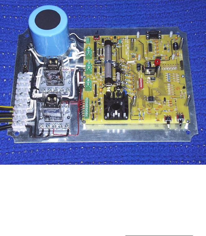
R&D PLATFORM:
THE SmartPAKTM CONTROLLER
DESCRIPTION
SmartPAKTM is the world's first all solid-state FREE ENERGY or OVER-UNITY power management s y s t e m t h a t t r a n s f o r m s a m b i e n t t h e r m a l environmental energy to excess electrical energy. It provides a "standard" platform for experimenters, researchers, and developers to do energy-related practical applications, experiments, and perform exploration of the OVER-UNITY phenomena.
The theory of operation is based on the difference of energy between magnetization/de-magnetization cycles of ferromagnetic materials utilizing a coil/ core or coil/core/magnet Head assembly. It has been discovered that EXCESS energy is released during the de-magnetization portion of the cycle using a suitable core assembly. The SmartPAKT M system is specially designed to measure, collect, and store this excess energy for later use.
The SmartPAK T M system is controlled by a M o t o r o l a 6 8 H C 9 0 8 G P 3 2 m i c r o c o n t r o l l e r programmed to measure input/output voltages and currents, calculate COP, and contains software algorithms for a complete "turn-key" power management system. The system features a "standard" user interface, which allows the user to design their own custom coil/core/magnet "head assemblies", and immediately test and display in real-time its' performance.
(c) INTALEK, INC., 2002 |
8 |
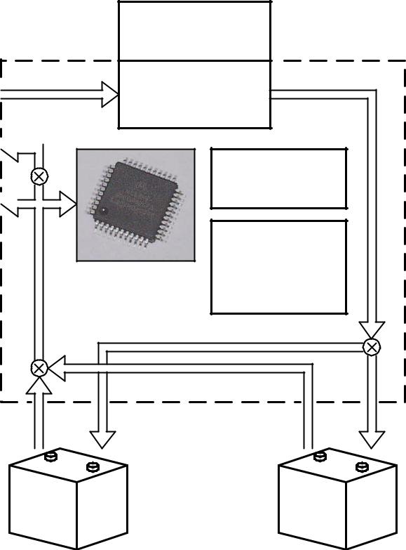
FUNCTIONAL BLOCK DIAGRAM
EXTERNAL
SUPPLY
OUTPUT 
LOAD
INTERNAL 
SUPPLY
SOURCE BATTERY
PATH "B"
CUSTOM
COIL/CORE/MAGNET
HEAD ASSEMBLY
SHOCK CHARGING
POWER CIRCUITRY
|
MICROCONTROLLER |
BATTERY |
|
INTERFACE |
|
|
|
|
|
CIRCUITRY |
|
|
16X2 LCD DISPLAY |
LOAD |
|
|
|
|
AND |
|
|
SIX PUSHBUTTON |
|
CONTROLLED BY |
SWITCHES |
|
(EXTERNALLY |
|
|
68HC908GP32 |
|
|
MOUNTED) |
|
|
MICROCONTROLLER |
|
|
|
|
|
|
PATH "A" |
|
PATH "A" |
|
PATH "B" |
|
|
BATTERY BANK 1 |
BATTERY BANK 2 |
(c) INTALEK, INC., 2002 |
9 |
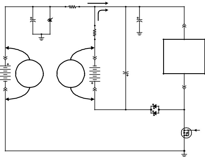
SmartPAK XX10-XX Coil Driver
I_EXT
|
R8 |
|
|
|
|
|
0.01 |
|
|
|
|
C1 |
3% |
I_LD_BAT |
C28 |
|
|
D2 |
J7 |
||||
TANTALUM |
|
TANTALUM |
|||
|
|
|
|
|
R22 |
|
P1 |
|
|
|
|
0.01 |
|
|
|
|
|
|
|
|
|
|
|
|
|
3% |
|
+ |
|
|
|
|
|
|
|
|
|
|
|
|
|
User |
|
|
|
|
|
|
Designed |
|
|
+ |
- |
|
|
Head (POD) |
|
|
|
|
Assembly |
|
||
EXT |
V_EXT |
V_LD_BAT |
BAT1(2) |
C22 |
- |
|
TANTALUM |
|
|
||||
|
- |
+ |
|
|
P2 |
|
|
|
|
|
|
J6 |
|
|
NOTE: |
|
|
|
D13 |
|
|
|
|
|
|
|
|
|
COP = Pout / Pin |
|
|
|
|
|
|
where, |
|
|
|
|
|
|
Pout = V_LD_BAT x I_LD_BAT |
|
|
|
|
|
|
Pin = V_EXT x I_EXT |
|
|
D |
PWM |
|
|
|
|
|
|
||
|
|
|
|
|
G |
|
|
|
|
|
|
|
|
|
|
|
|
|
S |
|
|
|
|
|
|
Q7 |
|
ELECTRICAL DIAGRAM
NOTE:
VOLTAGES AVAILABLE: 12V, 24V, 36V, and 48V
(c) INTALEK, INC., 2002 |
10 |