

Phedotikov / 1 / FreeEnergy_27.01.08 / Схемотехнические / Генератор MEG / Build Electrical Over-Unity Devices
.pdfSHOCK CHARGING SYSTEM BY STEFAN HARTMANN
ELECTRICAL DIAGRAM
The Shock Charging System presented by Stefan Hartmann is classified as a CATEGORY 3A OverUnity Device. The excess electrical energy appears in the secondary coil of the transformer during the d e m a g n e t i z a t i o n p h a s e o f a m a g n e t i z a t i o n / demagnetization cycle.
The magnetization phase of the cycle is initiated by closing switch S1. The fluroescent tube functions as current limiting resistor.
(c) INTALEK, INC., 2002 |
21 |
COMPARISON BETWEEN
T. BEARDEN'S MEG AND J. FLYNN'S PP
T. BEARDEN'S MEG
DESIGN
S2 |
+12V |
S1 |
|
|
|
|
|
+ |
STACK 1 |
+ |
|
VOUT2 |
VOUT1 |
||
MAGNET |
|||
- |
- |
||
|
J. FLYNN'S PARALLEL
PATH DESIGN
|
|
|
S1-A |
S2-B |
|
|
|
+12V |
|
|
|
|
+ |
STACK 2 |
|
STACK 1 |
+ |
VOUT2 |
|
|
VOUT1 |
||
|
MAGNET |
|
MAGNET |
||
|
- |
|
- |
||
|
|
|
|
||
|
|
|
S2-A |
S1-B |
|
|
|
+12V |
|
|
|
BOTH DESIGNS HAVE IDENTICAL SWITCH STATES
 T1
T1 
 T2
T2 
CLOSED
S1
OPEN
CLOSED
S2
OPEN
SWITCHING CHARACTERISTICS
The Flynn design has a more efficient input switching scheme than the Bearden design.
(c) INTALEK, INC., 2002 |
22 |
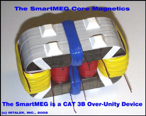
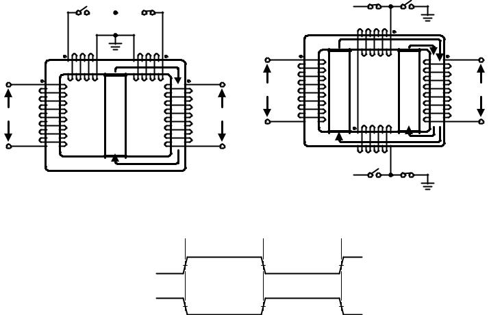
THE SmartMEG
OVER-UNITY DEVICE
The SmartMEG is classified as a CATEGORY 3B Over-Unity Device.
The design implements the efficient Flynn input scheme. This devices uses the series-wired control coils and a double magnet stack.
(c) INTALEK, INC., 2002 |
23 |
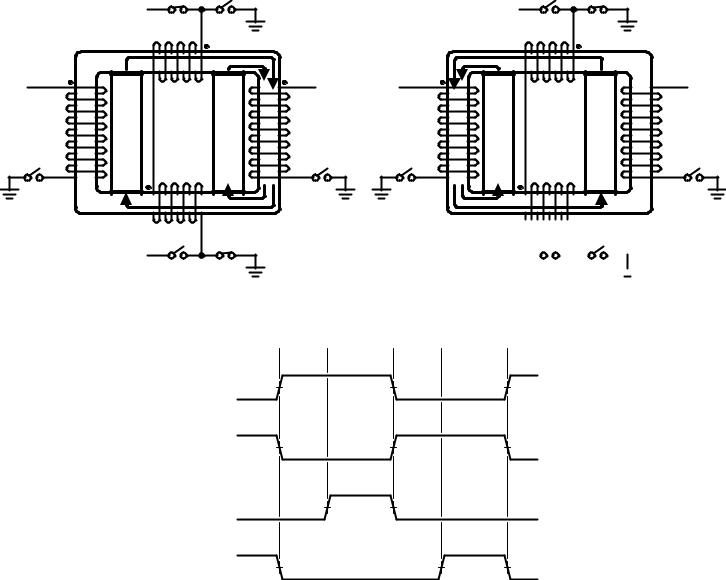
THE SmartMEG SWITCHING STATES
|
|
|
|
S1-A |
S2-A |
|
|
|
|
|
|
+12V |
|
|
|
|
|
|
|
|
|
|
+ |
|
|
|
|
|
+ |
2 |
|
1 |
+ |
|
+ |
VOUT2 |
|
|
|
|
VOUT1 |
VOUT2 |
||
|
|
STACK |
|
STACK |
|
|||
|
|
|
|
|
|
|
||
|
S4 |
|
MAGNET |
|
MAGNET |
|
S3 |
S4 |
|
|
|
|
|
|
|||
|
|
- |
|
|
|
- |
|
- |
|
|
|
|
|
- |
|
|
|
|
|
|
+12V |
S2-B S1-B |
|
|
|
|
|
|
|
|
|
|
|
||
|
|
|
|
|
|
ELECTRICAL DIAGRAM |
||
|
S1-A S2-A |
+12V |
|
|
- |
MAGNET STACK 2 |
MAGNET STACK 1 |


 +
+
+12V 


 S2-B S1-B
 +
+
-
VOUT1
S3
 T1
T1 
 T2
T2 
 T3
T3 
 T4
T4 
CLOSED
S1
OPEN
CLOSED
S2
OPEN
CLOSED
S3
OPEN
CLOSED
S4
OPEN
SWITCHING CHARACTERISTICS
T1 & T3 : Wait for full flux transfer.
T2 & T4 : Activate output switches. Collect excess energy.
When S3 and S4 are open, the intended secondary coil has a voltage bounded by Faraday's Law to the total flux flowing through its' core. This flux is the sum total of the two magnet stacks flux and the control coils flux.
(c) INTALEK, INC., 2002 |
24 |
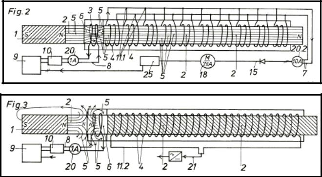
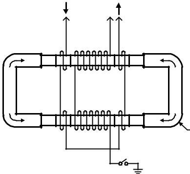
THE Heinrich Kunel PATENT
(DE3024814) January 1, 1982
The Heinrich Kunel patent is classified as a CATEGORY 3C Over-Unity Device, but NOT as shown in the patent.
The "correct" operation of this device appears to be a combination of the SmartMEG and the Adams Motor. The magnetization of the control coil cancels the field flowing through the flux gate . Then, reverse magnetization of the same causes flux from the control coil plus the flux from the magnet to magnetize the core. An output delay turn-on circuit may be required as a caveat to ensure magnet flux transport across the air gap. Excess energy can then be collected in the output coil.
(c) INTALEK, INC., 2002 |
25 |
B
μoH
THE SmartPAK KPOD
OVER-UNITY DEVICE
|
|
IC |
|
|
IC |
|
|
|
|
|
L3 + |
L1 |
|
L6 |
|
|
|
|
|
2.5mH + |
|
|
NOTE 1: |
|||
S |
N |
AIR |
FERRITE |
AIR |
S |
N |
μoH: Produced by coil L1 and L2. |
|
RODS |
B: Produced by magnet MAG1 - MAG4. |
|||||||
|
|
|
|
|
|
|||
|
MAG1 |
|
|
+ |
MAG2 |
|
μoH |
|
|
|
|
|
L1 and L2 use 50ft of 16AWG magnet wire |
||||
|
|
|
|
|
|
|||
|
|
|
|
|
|
|
||
|
|
|
|
|
|
|
each. |
|
|
MAG3 |
|
|
|
MAG4 |
|
C-Core: METGLAS, AMCC-500. |
|
|
|
|
|
|
B |
|||
|
|
+ |
+ |
|
|
|
MAG1 - 4 are NIB type magnets. |
|
|
|
|
|
|
|
|||
N |
S |
AIR |
FERRITE |
AIR |
N |
S |
|
|
RODS |
METGLAS |
|||||||
|
|
|
|
|
|
|||
|
|
|
|
+ |
|
|
||
|
|
L4 |
L2 |
L5 |
|
C-CORE |
||
|
|
|
2.5mH |
|
|
|
|
|
|
|
|
|
S1 |
|
|
||
ELECTRICAL DIAGRAM
The SmartPAK KPOD is classified as a CATEGORY 3C Over-Unity Device.
The coils L3 - L6 are the flux control gates, and are operated bidirectionally (AC). The actual operation is very similar to the Flynn input design. Output delay turn-on is provided by switch S1. This will ensure the magnet flux is transported across the air gap.
Excess energy is collected in output coils L1 and L2.
(c) INTALEK, INC., 2002 |
26 |
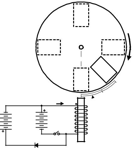
THE Adams MOTOR
N
S
N |
S |
TDC
S
N
|
|
I |
+ |
|
|
|
|
Source |
Source |
|
|
Battery |
Battery |
|
|
(BAT2) |
(BAT1) |
S1 |
|
|
|
|
|
|
D1 |
|
- |
|
|
|
DIRECTION
S |
N |
OF ROTATION |
|
|
S
N
 MAGNETIZATION PHASE
 DEMAGNETIZATION PHASE
NOTE:
S1 is closed during the magnetization phase of a magnetization / demagnetization cycle.
ELECTRICAL DIAGRAM
The Adams Motor is are classified as a CATEGORY 3C Over-Unity Device.
As the magnet approaches Top-Dead-Center (TDC), maximum influence of the magnet flux with the coil/ core demagnetization phase is obtained. Hence, the coil/core demagnetization energy is greater than the magnetization energy.
As the magnet moves past TDC, the influence of its flux with the coil/core decreases.
(c) INTALEK, INC., 2002 |
27 |
FUTURE RESEARCH
GRAVITONICS
I s a s c i e n t i f i c d i s c i p l i n e t h a t i n v e s t i g a t e s ferromagnetic-based methods and devices that control or influence gravity.
The latest Russian research shows a correlation between magnetostriction and gravity.
Develop the Gravito-Ferromagnetic Space Drive.
THERMOFERROMAGNETICS
I s a s c i e n t i f i c d i s c i p l i n e t h a t i n v e s t i g a t e s ferromagnetic-based methods and devices that c o n t r o l o r i n f l u e n c e t h e a m b i e n t t h e r m a l environment.
The latest Russian research shows a correlation between magnetostriction and the ambient thermal environment.
(c) INTALEK, INC., 2002 |
28 |
REFERENCES
1.Nicolas Zaev, "Inductive Conversion of Heat Environmental Energy to Electrical Energy", 1999.
2.Nicolas Zaev, "Fuel-less Energetics", 1999.
3.William Alek, "The Motionless Battery Shock Charger", 2001.
4.Jean-Louis Naudin, "The Parametric Power Conversion", 1997.
5.Leon Dragone, "Energetics of Ferromagnetism", 1989.
6.William Alek, "Analysis of Leon Dragone's, Energetics of Ferromagnetism", 2002.
7.Spartak and Oleg Poliakov, "Gravitonics is Electronics of the 21st Century", 2000.
8.Hayt & Kemmerly, "Engineering Circuit Analysis", McGraw Hill, 1993.
9.Col. William McLyman, "Transformer and Inductor Design Handbook", Marcel Dekker, 1988.
10.Technical Marketing Staff of Gates Energy Products, Inc., "Rechargeable Batteries, Applications Handbook", Butterworth-Heinemann, 1992.
11.Del Toro, "Electromechanical Devices for Energy Conversion and Control Systems", 1968.
12.Halliday & Resnick, "Physics Part II", 1960, 1962
13.Pressman, "Switching Power Supply Design", 1998.
14.William H. Clark, "Pulsed Current Battery Charging Method and Apparatus", US Patent 3,963,976, June 15, 1976.
15.Paul Meretsky, Amiran Carmon, "Inductive Device Having Orthogonal Windings", US Patent 4,210,859, July 1, 1980.
16.H. Kunel, "Procedures and Devices for Energy Production", DE3024814, Jan. 28, 1982.
17.H. Aspden and R. Adams, "Electrical Motor-Generator", GB2282708, Sept. 30, 1993.
18.T. Bearden and co., "Motionless Electromagnetic Generator", US Patent 6,362,718, Mar. 26, 2002.
19.C. Flynn, "Methods for Controlling the Path of Magnetic Flux from a Permanent Magnet and Devices Incorporating the Same", US Patent 6,246,561, June 12, 2001.
20.Tim Harwood's Over-Unity CD Motor, http://www.geocities.com/theadamsmotor/ cdmotor.html.
(c) INTALEK, INC., 2002 |
29 |