

Phedotikov / 1 / FreeEnergy_27.01.08 / Схемотехнические / Генератор MEG / Magnetic Technology
.pdfParallel Path
Magnetic
Technology
Flynn Research
Defining The Shape Of Science & Technology
Visit Us On The Web At http\\www.flynnresearch.net
A Greater Force Of Attraction / Unit Of Electrical Input Can Be Achieved With Parallel Path Magnetic Technology........ Than With Any Conventional Electro-Magnetic Systems In Use Today.
The Foundation of Parallel Path Magnetic Technology:
The Judicious placement of Magnets and Coils on Flux paths that allow For a
Magnet and Electro-Magnet to Act in Series and the Resulting Flux to Act in
Parallel with Another Permanent Magnet.
The Sum Of the Series Flux and The Parallel Flux in the Active Path is Twice the Amount That Would Be Produced By the Electro-Magnet Acting Alone.
The Definition of Parallel Path Magnetic Technology:
Parallel Path Magnetic Technology is therefore defined as a special application of a controllable magnetic circuit where the flux of one permanent magnet is ADDED to the flux of second permanent magnet.
The Application of Parallel Path Magnetic Technology:
Parallel Path Magnetic Technology can be applied to virtually any electro-magnetic application that produces a holding force or any motion.
Parallel Path Magnetic Technology is a Trademark of Flynn Research Inc. Copyright 1999 Flynn Research
Patents Pending
Flynn Research Inc.
Visit Us On The Web At http\\www.flynnresearch.net

Parallel Path
Technology Table
of Contents
Flynn Research
Defining The Shape Of Science
&
Technology
Visit Us On The Web At http\\www.flynnresearch.net
 Parallel Path Technology Table of Contents
 Page 1......Parallel Path Magnetic Technology, The Basics
Page 2...... |
Parallel Path, Geometry |
|||
Page 3...... |
Conventional Magnetic Circuit & Force Comparisons: |
|||
Page 4...... |
Determining Input Power |
|||
|
|
|
|
|
Page 5...... |
Finite Element Analysis of Parallel Path Magnetic Technology |
|||
|
|
|
|
|
Page 6...... |
Finite Element Analysis of the Three states of Parallel Path |
|||
|
|
|
Magnetic Technology |
|
Page 7 |
Test Set up |
|||
|
|
....... |
||
Page |
8 |
|||
Test Results |
||||
Page 9 |
Test Results Cont'd |
|||
|
|
....... |
||
Page |
10 |
|||
Linear Applications |
||||
Page 11...... |
Rotary Applications |
|||
|
|
|
||
Page 12...... |
Contact Us |
|||
|
|
|
|
|
Parallel Path Magnetic Technology is a Trademark of Flynn Research Inc. Copyright 1999 Flynn Research Patents Pending
Flynn Research Inc.
Page 1
Parallel Path Magnetic
Technology
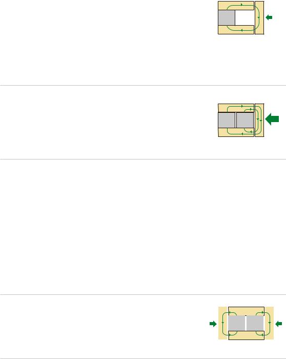
If a permanent magnet were placed in a magnetic circuit as shown, all of the flux from the permanent magnet would flow through the upper flux path to the armature and from the armature to the lower flux path and then return to the permanent magnet.
N
S 1 unit of Force
A magnetic force of attraction exists between the upper & lower flux paths and the armature. For this discussion we assign the amount of this force as 1 unit.
If another magnet with equal properties is added in parallel to the circuit as shown below the flux through the armature doubles. By doubling the flux in the magnetic circuit the force of attraction on the armature is now 4 units.
N |
N |
|
S |
S |
4 units |
|
|
|
|
|
of Force |
This is defined by the formula for the magnetic |
|
|
|
|
|
|
|
force of attraction. The formula is: shown at the right |
|
|
|
|
|
|
|
Where F is the force and B is the flux in the airgap |
|
|
|
|
|
|
|
and A is the area of a pole face in the air gap and |
|
|
|
β |
2 |
Α |
|
2uo is the magnetic constant. Since the only difference |
F |
= |
|
|
|||
between the first and second magnetic circuits is the |
|
|
|
|
|
||
|
2μο |
||||||
addition of a second magnet then wecan see that the |
|
|
|
||||
force of attraction can be defined as a function of
B squared. For those knowledgeable about magnet circuits, this is elementary, but is fundamental to understanding Parallel Path Magnetic Technology.
If the magnetic circuit is again modified by the addition of a second armature as shown below, each of the permanent magnets now have separate flux paths through their respective armatures.
|
|
|
|
|
|
|
|
|
|
|
|
N |
|
N |
|
|
|
1 unit |
|
|
S |
|
S |
|
|
1 unit |
|
|
|
|
|
|
|
||
of Force |
|
|
|
|
|
|
|
of Force |
It should now be obvious from the above discussion that the resulting force would be 1 unit acting on each armature. Now armed with this basic magnetic theory we are ready to discover what Parallel Path Magnetic Technology is and how it works.
Visit Us On The Web At http\\www.flynnresearch.net
Page 2 |
|
|
Parallel Path Magnetic Technology, |
|
|
The Geometry: |
|
|
The magnetic circuit is again modified by placing a coil on each |
|
|
|
|
|
flux path as shown at the right. If no current flows in the |
|
|
coils then the magnetic circuit remains the same as if the coils |
1 units |
|
do not exist. |
of Force |
|
|
|
|
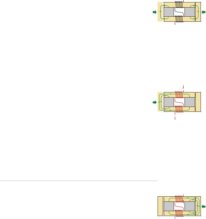
However if current flows in the coils to produce a magnetic |
|
|
polarity as shown at the right the resulting events occur. The |
|
|
magnetic flux produced by the coils couple with the permanent |
|
|
magnet flux and the result is as shown. The magnet on the |
|
|
right and the coils are magnetically in series. Since they are in |
|
|
series there is no gain in flux density. |
|
|
The magnet on the right and the coil's flux are now placed in |
|
|
parallel with the flux of the magnet on the left, with a resulting |
|
|
equivalent of the flux of both magnets passing through the |
|
|
armature on the left. The result is no force acting on the |
|
|
armature on the right and 4 units of force acting on the |
|
|
armature on the left. The coil only contributes 1/2 of the |
|
|
magnetic field that is producing the force on the left armature. |
4 units |
|
At this point the advantage of Parallel Path Magnetic |
of Force |
|
|
|
|
Technology should be obvious. |
|
|
The reason the flux cannot pass through the armature on the right is partly due to the axiom that a magnetic source's poles
will couple with the nearest opposite pole. However at the same time it is impossible for both the coil's flux and the magnet's flux to both pass through the armature on the right. Their fluxes would be traversing the armature in opposite directions. Flux can pass through the armature on the right, however, if an excess of flux is produced by the coil. Excessflux is covered on page 4.
The magnetic circuit at the right is identical to the preceding circuit with the exception of the polarity of the coils. The current through the coils is reversed and and thus the polarity
is reversed.
0 unit of Force
The sum of the fluxes now traverses the armature on the right resulting in 4 units of force acting on the armature on the right and no force on the armature on the left. The ability to arbitrarily move the force from one point to another is the basis for motion.
N |
N |
|
S |
S |
1 unit |
|
|
|
|
|
of Force |
I
N |
S |
|
|
N |
N |
0 unit |
|
S |
S |
||
of Force |
|||
S |
N |
|
|
|
I |
|
S |
N |
|
N |
I |
|
N |
|
|
S |
S |
4 units |
|
|
|
|
|
of Force |
N |
S |
|
 I
I
Page 3
Parallel Path Magnetic Technology vs.
Conventional Magnetic Circuit & Force Comparisons:
The same magnetic test apparatus, with magnets removed is used for the conventional comparison tests. The same electrical input is used in these examples as the electrical input required to move all of one of the permanent magnet's flux to the opposite armature with the magnets installed (Parallel Path Magnetic Technology). The amount of this electrical input is defined as 1 unit. All tests performed use 1 unit of electrical input.
The armatures on the left is applied without an air gap. The armature on the right has an air gap. Force is can only be exerted on the armature with the air gap.
0 unit
of Force
1 units of Force
Both Armatures have air gaps. This reduces the reluctance
of the circuit and divides the force between the two armatures.
.5 units |
.5 units |
of Force |
of Force |
Visit Us On The Web At http\\www.flynnresearch.net
Page 4
Parallel Path Magnetic Technology
Determining Input Power:
And The Effects of Excess Electrical Power Input.
The amount of electrical power required for maximum efficiency and force on a single armature is the amount of electrical power required to produce an equal number of lines of flux in the coil as is produced by 1 of the permanent magnets. The easiest way to determine this electrical input power is to slowly increase the power until zero force is exerted on the armature on the left by the flux paths.
This is defined as 1 unit of electrical input.
 I
I
|
S |
N |
|
0 unit |
N |
N |
|
S |
S |
|
|
of Force |
4 units |
||
|
|
|
of Force |
|
N |
S |
|
 I
I
If electrical input power exceeds 1 unit of electrical input, more lines of flux are produced by the coil than are produced by one of the permanent magnets. If the coil produces more lines of flux than the magnet produces, the coils excess flux traverses the upper and lower flux paths and through both armatures. The armature on the left experiences a force of attraction
that is function of the square of the excess flux produced by the coil. The armature on the right |
|||||||||||||||
also experiences an additional force that is a function of the |
|
|
|
|
|
|
|
|
|
|
I |
|
|
|
|
square of the excess flux. Ironically these two forces |
|
|
|
|
S |
|
|
N |
|
|
|
|
|||
|
|
|
|
|
|
|
|
|
|||||||
balance using the fixed air gap. Therefore the force on |
|
|
|
|
|
|
|
|
|
|
|
|
|
|
|
the armature on the right remains at 4 units of force. In |
|
|
|
N |
|
|
|
|
|
|
|
N |
|
|
|
|
|
|
S |
|
|
|
|
|
|
|
S |
|
|
|
|
practice where the air gap is time varying, as it would |
X units |
|
|
|
|
|
|
|
|
|
|
|
4 units |
||
|
|
|
|
|
|
|
|
|
|
|
|
|
|||
of Force |
|
|
|
|
|
|
|
|
|
|
|
|
|
of Force |
|
be in motion producing devices, the forces due to |
|
|
|
|
|
|
|
|
|
|
|
|
|
||
|
|
|
|
N |
|
|
|
S |
|
|
|
+ |
|||
|
|
|
|
|
|
|
|
|
|
||||||
excess flux when averaged over an appropriate time |
|
|
|
|
|
|
|
I |
|
|
|
|
|
X Units |
|
|
|
|
|
|
|
|
|
|
|
|
|
of Force |
|||
frame would be equal. However at a given instance the force,
due to excess flux. on one armature would be greater than the force on the other armature. In all cases the armature that contains the flux from the Parallel Path Magnetic Effect will always have the greater force. Therefore electrical power that exceeds 1 unit of electrical input is wasted.This would be true of all electromagnetic devices where a coil couples with a flux that is produced by a permanent magnet.
In the illustrations below the power through the coil is reversed. The effects of applying 1 unit of electrical power input and the application of electrical input that exceeds 1 unit are identical with the exception of force, with the same relationships, is acting on the opposite armatures.
|
|
I |
|
|
|
I |
|
|
N |
S |
|
|
S |
N |
|
|
N |
N |
0 unit |
4 units |
N |
N |
|
|
S |
S |
S |
S |
|
||
4 units |
of Force |
of Force |
X units |
||||
of Force |
|
|
|
+ |
|
|
of Force |
|
|
|
X Units |
|
|
||
|
S |
N |
|
N |
S |
|
|
|
|
of Force |
|
||||
|
|
I |
|
|
I |
|
|
|
|
|
|
|
|
Visit Us On The Web At http\\www.flynnresearch.net
Page 5
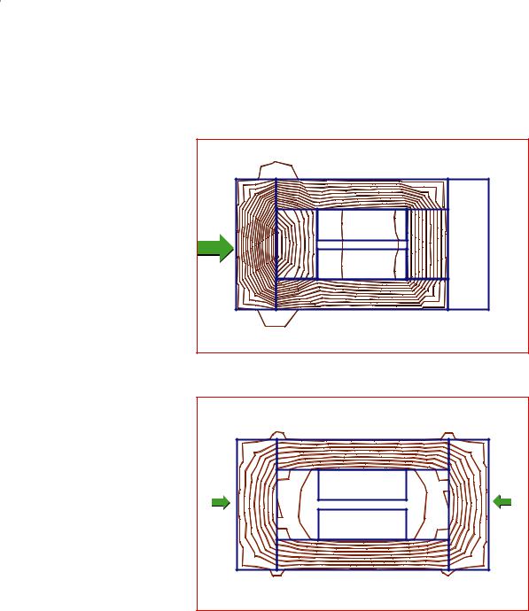
Parallel Path Magnetic Technology
Finite Element Analysis:
Below is a finite element analysis comparison of the magnetic circuit with the magnets installed, Parallel Path Magnetic Technology, and with the magnets removed, conventional technology. This analysis clearly shows the advantage of Parallel Path Magnetic Technology.
The Scale factor for both is .0003 webers, and the coil is energized identically in both systems, 1 unit of electrical input as described on page 4.
Parallel Path
Technology
Conventional
Technology
Air |
|
|
|
|
|
|
|
|
|
|
|
Steel |
|
|
|
|
|
N |
N |
Coil |
S |
N |
|
2 Units B |
|
|
|
|
|
|
|
|
|
|
|
|
|
|
|
Force |
Steel |
Magnet |
|
Air |
|
Magnet |
Steel |
|
|
|
|
||||
4 Units of Force |
S |
S |
Coil |
N |
S |
|
|
|
|
||||||
|
|
|
|
Steel |
|
|
|
|
|
|
Parallel Path System |
|
Air |
||
|
|
|
|
|
|
|
|
The Advantage Of Parallel Path Technology Can Be Clearly Seen in This Analysis Of Flux (B) & Force |
|||||||
Air |
|
|
|
|
|
|
|
|
|
Steel |
|
|
|
N |
S |
|
|
1 Unit B |
|
Coil |
|
1 Unit B |
|
|
|
||
Force Steel |
Air |
Air |
Steel |
Force |
|
|
|
1 Unit of Force |
|
1 Unit of Force |
|
|
|
|
|
Coil |
|
|
|
|
S |
|
|
|
|
N |
|
|
|
|
|
Steel |
|
|
|
Conventional System |
|
Air |
|
Visit Us On The Web At http\\www.flynnresearch.net
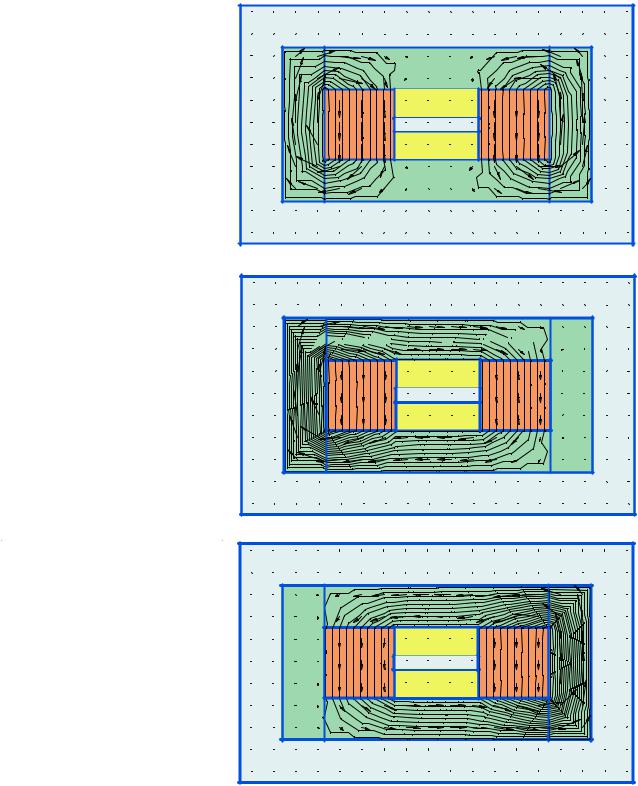
Page 6
Three States of
Parallel Path Magnetic
Technology
Scale = .005 weber
Finite Element Analysis:
|
Air |
|
|
|
No power in Coil |
|
Steel Armature |
|
|
|
|
|
||
Analysis shows 10 lines through |
S |
coil off |
S |
|
magnet |
AIR |
magnet |
||
each armature: |
||||
N |
coil off |
N |
||
|
||||
10 x .005 = .5 weber |
|
|
|
|
|
|
|
Air |
Coil powered to place all flux through left armature.
Analysis shows 20 lines through left armature:
20 x .005 = .1 weber
Indicating the flux doubles as predicted
Coil powered to place all flux through right armature.
Analysis shows 20 lines through right armature:
20 x .005 = .1 weber
Indicating the flux doubles as predicted
Air


 Steel Armature


S |
S coil N |
S |
magnet |
AIR |
magnet |
N |
N coil S |
N |
|
|
Air |
Air |
|
|
|
Steel Armature |
|
S |
N coil S |
S |
magnet |
AIR |
magnet |
N |
S coil N |
N |
|
|
Air |
Page 7
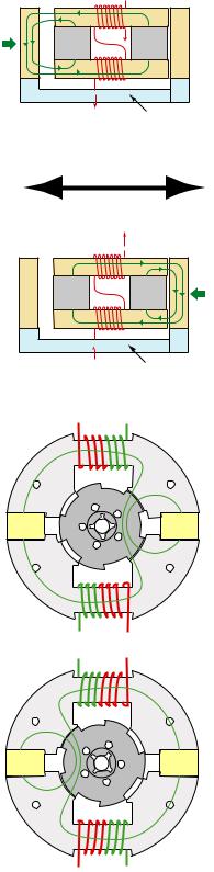
Application Of Parallel Path Technology to Rotary & Linear Motion:
The application of Parallel Path Magnetic technology for the production of linear motion or rotary motion is fairly simple and does not vary much from the test apparatus.
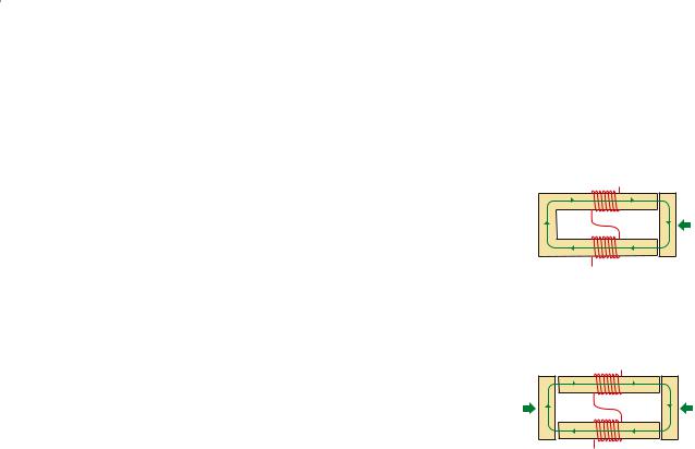
Linear Motion:
If the armatures on the test apparatus were mechanically coupled the result would be a basic linear motion device.
Depending on the polarity of the coil, one of the two armatures would be attracted to the upper & lower flux paths. This would produce a simple back and forth motion which has utility as a Linear servo or a linear pump.
There are many forms of linear devices, both simple & complex, utilizing Parallel Path Magnetic Technology.
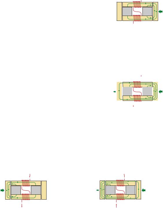
Rotary Motion:
Observe the similarities between the linear motion device above and the rotary motors at the right. The stators and magnets are the same as the flux path sand magnets in the linear device. The coils are located identical to the coils in the linear device. The rotor poles simulate the linear armatures where one set aligns across one of the two magnet stator poles at different angles during rotation.
|
N |
S |
|
|
N |
I N |
|
4 units |
S |
S |
0 unit |
|
|
||
of Force |
|
|
of Force |
|
S |
N |
|
|
|
I |
|
|
Mechanical Coupling |
|
|
|
Motion |
|
|
|
|
I |
|
|
S |
N |
|
|
N |
N |
|
0 unit |
S |
S |
4 units |
|
|
||
of Force |
|
|
of Force |
N S
I |
Mechanical Coupling
N |
S |
N |
N |
S |
S |
S N
Rotation is obtained by alternating the polarity of the coils. The rotor poles align with the stator magnet poles on one side of the structure during one coil polarity and then align with the stator magnet poles on the other side of the structure with the coil has the opposite polarity. The motor lends itself to both ac, and brush or brushless dc operation more about the motor control and motor characteristics or for a demo of a prototype motor.
N |
S |
N |
N |
S |
S |
S |
N |
Visit Us On The Web At http\\www.flynnresearch.net
|
|
|
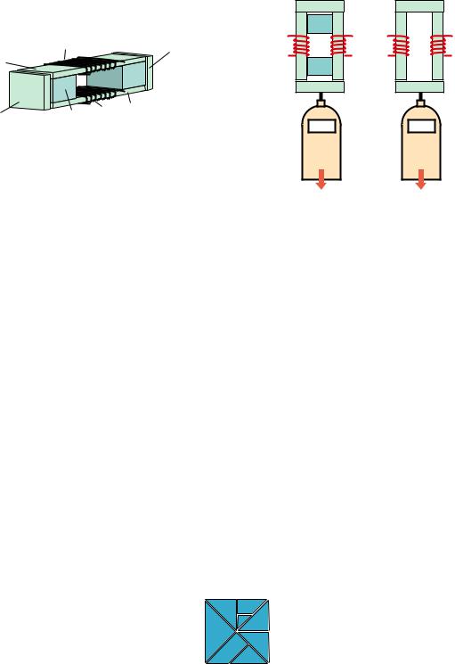
Page 8 |
Flynn Research |
|
Test Setup |
Defining The Shape Of Science & Technology |
|
|
|
|
A Greater Force Of Attraction / Unit Of Electrical Input Can Be Achieved With Parallel Path Magnetic Technology........ Than With Any Conventional Electro-Magnetic Systems In Use Today.
Coil |
Movable Armature |
Upper Flux Path
 Magnet
Lower Flux Path
Movable Armature |
Magnet Coil |
Linear Actuator Test Apparatus
Armature A
N S
N S
Armature B
0000
Armature A
Armature B
0000
Materials |
Test Procedure |
The material used for the flux paths and armatures is Hyperco. The magnets are Ceramic VIII. The coils are 80 T of 22 Ga copper for each coil. The Hyperco can be substituted with any magnetic material with high permeability and low retentivity such as silicon steel.
To request a drawing with the exact dimensions for the test apparatus, e-mail your request to drawing@flynnresearch.net or call Dave (573) 545-4546.
Companies or Universities may request to borrow an assembled test piece for 2 weeks for testing.
A digital force gauge capable of reading up to 5000 Grams is attached to one of the armatures. The Gauge is set on 'hold' to capture maximum force. Power is applied to where zero force is present on armature 'A'. Armature 'B' is pulled from the test apparatus using the force gauge. The measurement is then recorded. Several tests can be made and the results averaged if desired. To measure the conventional electromagnetic equivalent the permanent magnets are removed from the test apparatus. With the exact same amount of power applied to the coils as in the first test armature 'B' is again pulled from the test apparatus using the force gauge. The measurement is then compared with the Parallel Path system. Additional force tests as shown on our Tests page can also be performed.
Share your test results eith us, e-mail to: debate@flynnresearch.net
Parallel Path Magnetic Technology is a Trademark of Flynn Research Inc. Copyright 1999 Flynn Research
Patents Pending
Flynn Research Inc.
Visit Us On The Web At http\\www.flynnresearch.net