

Phedotikov / 1 / FreeEnergy_27.01.08 / Схемотехнические / Генератор MEG / Build Electrical Over-Unity Devices
.pdfTHE SmartPAK POD
NEAR-UNITY DEVICE
B
μoH
|
|
|
L1 |
|
I |
|
|
|
|
|
|
|
|
|
2.5mH |
+ |
|
S |
|
N |
FERRITE |
S |
N |
|
RODS |
||||
|
|
|
|
|
|
|
MAG1 |
|
- |
|
MAG2 |
|
|
|
|
||
|
MAG3 |
|
|
+ |
MAG4 |
N |
|
S |
FERRITE |
N |
S |
|
RODS |
||||
|
|
|
|
|
-L2
I 2.5mH
μoH
B
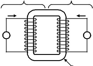
NOTE 1:
μoH: Produced by coil L1 and L2.
B: Produced by magnet MAG1 - MAG4.
L1 and L2 use 50ft of 16AWG magnet wire each. C-Core: METGLAS, AMCC-500.
MAG1 - 4 are NIB type magnets.
METGLAS
C-CORE
ELECTRICAL DIAGRAM
The SmartPAK POD is classified as a CATEGORY 2 Near-Unity Device. The coil L1 and L2 fields are mutually coupled to the ferrite rods' magnetic domains, which are magnetized in an opposing direction by permanent magnets.
(c) INTALEK, INC., 2002 |
11 |

THE NEAR-UNITY MODEL
OF THE SmartPAK POD
With switch S1 closed, the current (iBAT1 ) flows from the source battery (BAT1) and magnetizes coil L.
This action transfers or discharges energy from the source battery (BAT1) and stores it in L.
|
|
|
+ |
|
|
Source |
iBAT1 |
vL |
|
iBAT2 = 0 |
Load |
Dipole |
L |
Dipole |
|||
(BAT1) |
|
|
|
|
(BAT2) |
|
|
|
- |
|
|
|
S1 |
|
|
D1 |
|
t<0
MAGNETIZATION PHASE OF CYCLE
When switch S1 opens, the voltage (vL) across the coil L reverses (Lenz's Law) and the energy stored in
L flows out as a high-current impulse (iBAT2). Energy is transferred from L to the load battery (BAT2).
 -
-
Source |
iBAT1 = 0 |
vL |
L |
iBAT2 |
Load |
Dipole |
Dipole |
||||
(BAT1) |
|
|
|
|
(BAT2) |
|
|
|
+ |
|
|
|
S1 |
|
|
D1 |
|
t ³ 0
DEMAGNETIZATION PHASE OF CYCLE
(c) INTALEK, INC., 2002 |
12 |
THE ENERGETICS OF
FERROMAGNETISM
EXTERNAL |
PERMANENT |
|
COIL |
MAGNET |
|
IC |
|
IM |
+ |
N |
+ |
V |
LC LM |
A |
- |
S |
- |
POLARIZED
FERROMAGNETIC
MATERIAL
CLASSIC TRANSFORMER ANALYSIS
The total field energy of the system is,
ESYS = EM + EC - EMUTUAL |
1 |
where,
ESYS is total field energy.
EM is energy of permanent magnet (pm). EC is energy of coil.
EMUTUAL is mutual energy between coil and ferromagnetic core coupled to a pm.
(c) INTALEK, INC., 2002 |
13 |

Differentiating ESYS with respect to time is the total instantaneous power, PSYS or,
ESYS = PSYS |
2 |
Because EM is conserved and does NOT change over time,
EM = PM = LM IM IM = 0 Watts |
3 |
Now, rewriting PSYS,
PSYS = PC - PMUTUAL |
4 |
So,
P |
SYS |
= L I |
C |
I |
C |
+ I |
C |
2 L - M I |
M |
I |
C |
5 |
|
C |
|
|
C |
|
|
||||||
|
|
FLUX |
|
PARAMETRIC |
|
|
|
|
||||
|
|
COUPLING COUPLING |
|
|
|
|
||||||
|
|
TERM |
|
|
TERM |
|
|
|
|
|||
|
|
|
|
|
|
PC |
|
PMUTUAL |
|
|||
Now, of particular interest is LC of IC
CATEGORY 1 Under-Unity devices,
LC = 0 Ω |
6 |
(c) INTALEK, INC., 2002 |
14 |

However, by "strategically" polarizing the ferromagnetic material, this increases the permeability μ, and increases the inductance LC. This reveals the "hidden" mechanism that makes these CATEGORY 3 Over-Unity devices,
LC ¹ 0 Ω |
7 |
Since the coil dissipates power, the instantaneous power PSYS equates to,
P |
SYS |
= R I |
2 + L I |
C |
I |
C |
+ I |
2 L - M I |
M |
I |
C |
8 |
|
C |
C |
|
C |
C |
|
|
Since LC has the same units as resistance Ω, this resistance may be positive or negative depending upon the slope of LC. For example, if LC is "engineered" to be positive, then the power is positive, however, if LC is "engineered" to be negative, then the power is negative.
So, integrating PSYS with respect to time is the total energy, ESYS or,
ESYS = ò PSYS dt |
9 |
In conclusion, given special operating conditions, the ferromagnetic domain can serve as a "hidden" source of energy simply by mutually coupling it to a coil. The energy is in the form of excess electrical energy, and the domains transforms this energy from the ambient thermal environment. This causes an observable cooling effect in the domains.
(c) INTALEK, INC., 2002 |
15 |

THE FREE ENERGY "Alek Effect"
(B) |
|
DENSITY |
B-H CURVE |
|
|
PERMEABILITY and FLUX |
PERMEABILITY (μ) |
|
|
|
MAGNETIZING FORCE (H) |
NORMAL VARIATION OF μ ALONG MAGNETIZATION CURVE
DENSITY (B) |
|
|
FLUX |
MODIFIED PERMEABILITY (μm) |
|
and |
(CAUSED BY ELECTROSTRICTION / |
|
MAGNETOSTRICTION OF IRON |
||
|
||
PERMEABILITY |
ALLOY CORE) |
|
COMPONENT DUE TO |
||
|
B-H CURVE IS SHIFTED LEFT |
|
|
EXCESS FREE ENERGY |
|
|
INITIAL MAGNETIZATION |
MAGNETIZING FORCE (H)
MODIFIED VARIATION OF μ ALONG MAGNETIZATION CURVE
(c) INTALEK, INC., 2002 |
16 |
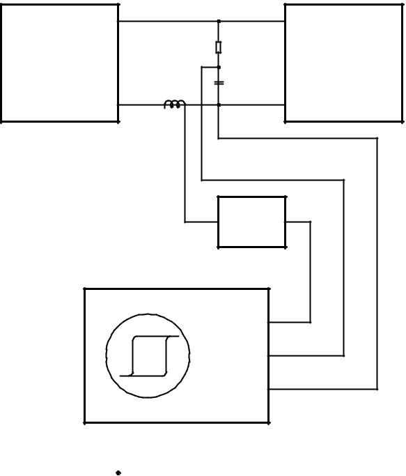
DYNAMIC B-H LOOP TEST FIXTURE
POWER |
10K |
"POD" HEAD |
OSCILLATOR |
|
ASSEMBLY |
(SQUARE WAVE) |
0.7uf |
UNDER TEST |
|
|
CURRENT
PROBE
P6042
HORIZ
VERT
SCOPE GND
Engineering LC will shift the BH curve either left or right.
(c) INTALEK, INC., 2002 |
17 |

The SmartPAK ZPOD
OVER-UNITY DEVICE
D1 |
|
|
|
|
|
|
|
|
|
|
|
|
|
|
|
|
n x LSEC |
||||||||
|
|
|
|
|
|
|
|
|
|
|
|
|
|
|
|||||||||||
|
|
|
|
|
|
|
|
|
|
|
|
|
|
|
|
||||||||||
+ |
|
LSEC1 |
|
|
LSEC2 |
|
|
LSEC3 |
|||||||||||||||||
|
|
|
|
|
|
|
|
|
|
|
|
|
|
|
|
|
|
|
|
|
|
|
|
|
|
|
|
|
|
|
|
|
|
|
|
|
|
|
|
|
|
|
|
|
|
|
|
|
|
|
|
|
|
|
|
|
|
|
|
|
|
|
|
|
|
|
|
|
|
|
|
|
|
|
|
|
|
|
|
|
|
|
|
|
|
|
|
|
|
|
|
|
|
|
|
|
|
|
|
|
|
|
|
|
|
|
|
|
|
|
|
|
|
|
|
|
|
|
|
|
|
|
|
|
|
|
|
|
|
|
|
|
|
|
|
|
|
|
|
|
|
|
|
|
|
|
|
|
|
|
|
|
|
|
|
H |
T1 |
H |
T2 |
H |
T3 |
o |
1:1 |
o |
1:1 |
o |
1:1 |
μ |
μ |
μ |
|||
|
|
|
+ |
LPRI2 |
LPRI3 |
LPRI1 |
||
|
|
LPRI |
|
|
n |
LSECn |
- |
H |
Tn |
o |
1:1 |
μ |
|
|
|
|
- |
|
LPRIn |
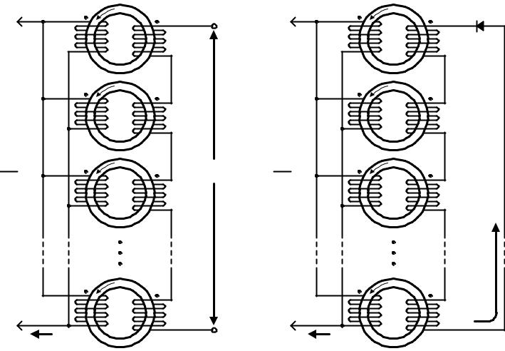
 SECONDARIES WIRED IN SERIES
 PRIMARIES WIRED IN PARALLEL
ELECTRICAL DIAGRAM
T h e S m a r t P A K Z P O D i s c o n s i d e r e d t o b e a Thompson-Plank PERPETUAL MOTION MACHINE, and is classified as a CATEGORY 3A Over-Unity Device.
(c) INTALEK, INC., 2002 |
18 |

THE OVER-UNITY MODEL
OF THE SmartPAK ZPOD
With switch S1 closed, the current (iBAT1 ) flows from the source battery (BAT1) and magnetizes coil L0.
This action transfers or discharges energy from the source battery (BAT1) and stores it in L0.
|
|
|
+ |
|
|
Source |
iBAT1 |
vL0 |
|
iBAT2 = 0 |
Load |
Battery |
L0 |
Battery |
|||
(BAT1) |
|
|
|
|
(BAT2) |
|
|
|
- |
|
|
|
S1 |
|
|
D1 |
|
t<0
MAGNETIZATION PHASE OF CYCLE
When switch S1 opens, the voltage (vL) across the coil L reverses (Lenz's Law) and the energy stored in L (increased permeability μ, of L0) flows out as a high-current impulse (iB A T 2 ). Excess energy is transferred from L to the load battery (BAT2).
 -
-
Source |
iBAT1 = 0 |
vL |
|
iBAT2 |
Load |
Battery |
L |
Battery |
|||
(BAT1) |
|
|
|
|
(BAT2) |
|
|
|
+ |
|
|
|
S1 |
|
|
D1 |
|
t ³ 0
DEMAGNETIZATION PHASE OF CYCLE
(c) INTALEK, INC., 2002 |
19 |
THE MAGNETIZATION / DEMAGNETIZATION CYCLE
+ |
μoH |
+ |
|
T1 |
|||
LPRI1 |
LSEC1 |
||
|
1:1 |
|
μoH |
|
LPRI2 |
T2 |
LSEC2 |
|
1:1 |
LPRI |
μoH |
HIGH |
n |
T3 |
VOLTAGE |
LPRI3 |
LSEC3 |
|
|
1:1 |
|
μoH |
|
LPRIn |
Tn |
LSECn |
- |
1:1 |
|
|
- |
|
iMAG |
|
|
|
|
MAGNETIZATION PHASE OF CYCLE
- |
μoH |
- |
D1 |
|
|||
T1 |
|
||
LPRI1 |
LSEC1 |
|
|
|
1:1 |
|
|
μoH |
|
LPRI2 |
T2 |
LSEC2 |
|
1:1 |
L |
PRI |
' |
μoH |
n x LSEC' |
|
n |
|
|
|
|
LPRI3 |
T3 |
|
|
|
|
LSEC3 |
||
|
|
|
1:1 |
HIGH
CURRENT
|
μoH |
|
LPRIn |
Tn |
LSECn |
+ |
1:1 |
|
|
+ |
|
iDEMAG |
|
|
|
|
DEMAGNETIZATION PHASE OF CYCLE
Excess electrical energy is released from the device d u r i n g t h e d e m a g n e t i z a t i o n p h a s e o f a magnetization/demagnetization cycle . A s a consequence of releasing this excess electrical energy, the device transforms it from the ambient thermal environment, thereby cooling itself.
(c) INTALEK, INC., 2002 |
20 |