

3. Measurement parameters and instrumentation
As shown in chapter 2, the actual measured variable is the resonance frequency. But for using eq. 1, another variable has to be known, that is the P-wave velocity vp or the depth of the discontinuity. lf the latter isn't known, and this is the reason for our investigations, vp has to be determined. (Knowing the dimensions of a specimen the method can be used for velocity measurements also).
3. 1. Measurement of the p-wave velocity
Usually, the P-wave velocity in materials is determined by measuring the travel time of a triggered pulse. Yet the travel distance between impactor and transducer has to be known. In the case of remote objects, this method is not applicable, since only the surface is accessible. At a little higher expenditure, it is possible to measure the P-wave velocity also on the surface of an object. The reason therefore is the propagation of the wave field also along the surface of the object. As shown in fig. 2, this measurement is enabled by an additional transducer at some distance from the other transducer. The signal produced by the impactor is triggering transducer a after a time t, and is reaching transducer b, travelling along the track S2. The travel time measured, the velocity easily can be computed:
Equation 2 : Vp = s2/t2 – tl
During one single test, with the same impactor-signal, it is possible to determine the P-wave velocity and simultaneously the object thickness. Thus it is possible to rewrite eq. 1 as:
Equation 3 : d = S2/2*Fr*dt with dt = (t2-t1)
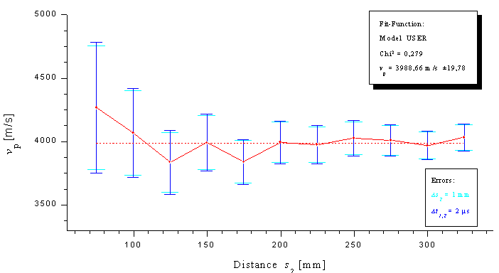
But as the travel path that is used for both measurements is not identical, the velocity measurement contains a systematic error. If the travel path is chosen too short, inhomogeneities under the surface of the concrete are affecting the measurement. Increasing error bars at decreasing distances of the transducers show the increasing scatter of the measured values. At about 25 cm the vp-values have reached a certain constancy at 4020 m/s (+/- 100 m/s). For further measurements of the compression wave velocity at the surface, thus the distance should not remain under this minimum.
3.2. Impactor signal
As this non-destructive testing method uses sound waves, the excitation of these waves is of considerable importance for the success of the measurement. Especially required is a wide range of frequency components in the radiated wave field. This is the only way to make sure that the frequency corresponding to the thickness of the object is stimulated. This is easy to realize by dropping a small spherical steel ball from a certain height down to the surface next to the transducer. Besides it's obvious, that the width of the frequency spectrum is inverse to the contact time of the steel ball on the surface of the object - an idealized delta-peak is producing a white spectrum, the widest spectrum that is possible. Therefore, it is important to use steel balls as small as possible for the excitation. The larger the diameter of the balls, the lower-frequent are the emitted signals. Usually, we used steel balls with diameters of 4-8 mm. Different energies, respectively amplitudes of the impulse may easily be attained by varying the height of fall. Carino & Sansalone suggested to use a steel ball which is hit by a spring bolt as impact source. The advantage of this Arrangement is a better control of the applied energy. But this parameter is not decisive.