

Requirements
The goal of the Requirements workflow is to describe what the system should do and allows the developers and the customer to agree on that description. To achieve this, we elicit, organize, and document required functionality and constraints; track and document tradeoffs and decisions.
A Vision document is created, and stakeholder needs are elicited. Actors are identified, representing the users, and any other system that may interact with the system being developed. Use cases are identified, representing the behavior of the system. Because use cases are developed according to the actor's needs, the system is more likely to be relevant to the users. The following figure shows an example of a use-case model for a recycling-machine system.
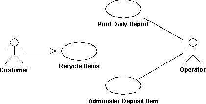
An example of a use-case model with actors and use cases.
Each use case is described in detail. The use-case description shows how the system interacts step by step with the actors and what the system does. Non-functional requirements are described in Supplementary Specifications.
The use cases function as a unifying thread throughout the system's development cycle. The same use-case model is used during requirements capture, analysis & design, and test.
Analysis and Design
The goal of the Analysis and Design workflow is to show how the system will be realized in the implementation phase. You want to build a system that:
-
Performs-in a specific implementation environment-the tasks and functions specified in the use-case descriptions.
-
Fulfills all its requirements.
-
Is structured to be robust (easy to change if and when its functional requirements change).
Analysis and Design results in a design model and optionally an analysis model. The design model serves as an abstraction of the source code; that is, the design model acts as a 'blueprint' of how the source code is structured and written.
The design model consists of design classes structured into design packages and design subsystems with well-defined interfaces, representing what will become components in the implementation. It also contains descriptions of how objects of these design classes collaborate to perform use cases. The next figure shows part of a sample design model for the recycling-machine system in the use-case model shown in the previous figure.
Part of a design model with communicating design classes and package group design classes.
The design activities are centered around the notion of architecture. The production and validation of this architecture is the main focus of early design iterations. Architecture is represented by a number of architectural views. These views capture the major structural design decisions. In essence, architectural views are abstractions or simplifications of the entire design, in which important characteristics are made more visible by leaving details aside. The architecture is an important vehicle not only for developing a good design model, but also for increasing the quality of any model built during system development.