

VI. Translate into English: Зерноуборочные комбайны.
Для уборки прямым комбайнированием, а также для подборки и обмолота валков используют самоходные зерноуборочные комбайны.
Устройство и принцип работы комбайнов в основном аналогичны. Различаются они размерами, пропускной способностью молотилки, устройством отдельных агрегатов.
Пропускную способность молотилки оценивают предельным количеством хлебной массы, которое может обрабатывать комбайн за одну секунду с соблюдением агротехнических требований. Пропускную способность комбайнов определяют при обмолоте хлебной массы соотношением содержания зерна к соломе.
Жатка комбайна предназначена для скашивания, сбора хлебной массы и транспортировки ее к молотильному аппарату. При раздельной уборке жатка служит для подбора хлебной массы из валка и подачи ее к молотильному аппарату.
Жатки современных комбайнов копирующие, они автоматически обеспечивают заданную высоту среза. К комбайнам выпускают несколько жаток, отличающихся шириной захвата. Жатка комбайна состоит из самой жатки и наклонной камеры. Корпус наклонной камеры присоединен к корпусу молотилки шарнирно и гидроцилиндрами, может подниматься и опускаться, поворачиваясь вокруг шарниров. Корпус жатки подвешен к наклонному корпусу в трёх точках: в центре при помощи сферического шарнира и по сторонам при помощи подвесок, соединенных с блоками пружин механизма уравновешивания через рычаги. Конструкция уравновешивания автоматически обеспечивает постоянное давление жатки на башмаки при любых её перекосах.
Режущий аппарат предназначен для срезания растений при прямом комбайнировании. Он состоит из пальцев, закрепленных на брусе, и ножа с насеченными сегментами. Пальцы снабжены противорежущими пластинами. К левому концу спинки ножа прикреплена головка с шаром для присоединения механизма привода. Нож приводится в движение кривошипно-шатунным механизмом.
Для отделения срезаемых стеблей от хлебной массы и подвода крайних стеблей к ножу применяют делители.
Мотовило подводит стебли к ножу, поддерживает их во время среза, подает их к шнеку и очищает от них режущий аппарат. Применяют универсальное эксцентриковое, планчатое и копирующее мотовила.
Part II
1. Read the text and translate it.
2. Study the vocabulary and prepare your own sentences with them.
3. Be ready to explain the vocabulary words.
Vocabulary
concave – дека, подбарабанье
grate(s) - грохот, решета, сетка
rasp-bar – рашпили, рашпильные решета
beater – цеп, битер
grain pan – стрясная доска
rack – граблина
straw walker – клавиша соломотряса
shoe sieve – нижнее решето
chaffer - решето первой очистки
tailing auger – нижний колосовой шнек
Principal units of the combine (continued)
III. Threshing Unit. Threshing removes the grain or seed from the head or pod. The major parts of this unit are the cylinder, the concaves and the grates.
A. CYLINDER: three different types are used (Fig. 2).
(a) Spike-tooth. This is the oldest type: it was used in stationary threshers that preceded the combine. It has proved quite satisfactory for threshing most grain crops. The spike teeth, carried in the transverse bars of the cylinder, thresh out the grain as they revolve through similar teeth in the concaves.


(b)

Fig. 2. Three types of cylinders: (a) spike-tooth cylinder, (b) rasp-bar cylinder, (c) angle-bar cylinder (USDA).
(b) Rasp-bar. This type has transverse bars with grooved metal faces. These grooves are cut diagonally, in opposite directions, across adjacent bars. Threshing is done by the rasping action between the cylinder bars and the solid concave bars below the cylinder.
(c) Angle-bar. The spiral bars of this cylinder are rubber-faced, the rubber being vulcanized to the metal. They flail out the grain between the revolving cylinder bars and the stationary shelling plate and stationary block rubber concaves.
B. CONCAVES AND GRATES. These stationary bars and open grates extend across the full width of the cylinder (Fig. 4). They are located below the cylinder and surround about one-quarter of its circumference. Hence they are called "concaves."

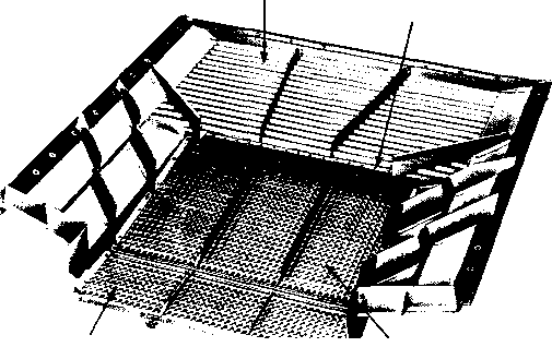
Fig. 3. Concaves, beater, deflectors, straw rack, and grain conveyor (John Deere).
Various types are used but all do the same work. Together with the cylinder, the concaves apply a basic principle used in all models, that of passing the grain between a rapidly revolving cylinder and a stationary surface.
Spike-tooth concaves are used with spike-tooth cylinders, rasp-bar or channel-bar concaves with rasp-bar cylinders, and rubber-block concave bars with rubber-bar cylinders.
Open grates with slotted holes or perforations are placed between the concave bars. Much of the threshed grain falls through these openings to the grain pan beneath.
IV. Separating Unit. Most of your threshed grain is separated from the straw at the concaves and at the finger grate at the rear of the cylinder. But some is mixed with the mass of straw thrown from the rear of the cylinder.
Removing this threshed grain from the mass of straw is accomplished by the straw rack (Fig. 3) which tosses and tumbles the straw and propels it to the rear. This aggressive motion separates threshed grain from the straw; the grain falls through openings in the bottom of the rack to the grain pan or to the grain conveyor. The straw travels the full length of the rack and is discharged at the rear of the combine.
A revolving beater strips the straw from the rear of the cylinder and distributes it to the straw rack. Deflectors or rotary beaters above the rack regulate the movement of the straw and deflect flying kernels.
In some models, the straw rack has four longitudinal sections. These are driven by a four-throw crankshaft which gives an alternate lifting and dropping motion as the straw is "walked" toward the rear. Figure 4 shows the flow of material from these straw "walkers' into a straw-chopping attachment which brings important advantages under certain field conditions.

Fig. 4. Straw chopper attachment for combine (International Harvester Co.).
V. Cleaning Unit. This unit (Figs. 5 and 6) removes chaff and fine residue from the threshed grain. It cleans by the combined action of sieves and an air blast.
A. GRAIN PAN. The grain pan is located so that all threshed grain may fall onto it – both that which passes through the concaves and that which sifts through the straw rack. The grain pan extends from beneath the cylinder to a point well back toward the rear.
The motion of the grain pan moves the grain toward the rear.
Grain pan
Grain pan fingers
Chaffer Chaffer
extension
Fig. 5. Grain pan. chaffer, and chaffer extension (International Harvester Co.).
B. CHAFFER. This is an extension of the grain pan. It has relatively large, adjustable openings. Threshed grain drops through these openings to the cleaning sieve, but unthreshed heads and larger pieces of residue are carried back to the chaffer extension.
C. CHAFFER EXTENSION. This short unit is hinged to the rear of the chaffer. The grain pan, chaffer, and chaffer extension are usually a single unit.
The chaffer extension has adjustable openings that can be raised or lowered. When it is properly adjusted, unthreshed heads fall through the openings into the tailings auger. But large particles and coarse residue are carried out the rear.
In some models there is a tailboard at the end of the chaffer extension. You can raise this, if necessary, to prevent grain from being blown out.

Fig. 6. Cleaning shoe, shoe sieve, and fan (International Harvester Co.).
D. TAILINGS AUGER. This conveys the unthreshed heads across the rear of the combine into the tailings elevator. The elevator returns the "tailings" 'to the cylinder for rethreshing.
E. SHOE SIEVE. Located below the chaffer, this adjustable sieve permits the grain to fall through it; then the grain moves down the inclined surface of the shoe to the grain auger. The shoe sieve has an oscillating or shaking motion. This aids in cleaning and sifts the grain through the sieve openings.
The position or angle of this sieve in the shoe is adjustable as is the size of its openings. The sieve is usually placed in the shoes with a slight angle downward, toward the fan and grain auger. For cleaning dirty grain, you can raise the rear of the sieve and increase the air blast.
F. FAN. In most designs the blast of air from the fan passes through the shoe sieve, the chaffer, and the chaffer extension and is regulated by doors (blinds) at the fan housing. The air blows the light straw and chaff out of the combine but permits grain to sift through the chaffer and shoe sieve to the grain auger.
VI. Grain-Handling Unit. This power-driven unit conveys the threshed, cleaned grain to the point at which it is taken from the combine. It includes these parts: clean grain auger; clean grain elevator; and grain tank and tank unloader, or bagger and bag chute.
The clean grain auger collects the clean grain at the bottom of the shoe and conveys it across the combine to the elevator.
The clean grain elevator extends upward along one side of the combine. It elevates grain from the auger and discharges it into the grain tank or bagger.
The grain tank retains the cleaned grain until a truckload or wagonload has accumulated. Capacities of grain tanks vary from 18 to 60 bushels or more depending on the size of the combine. A power-driven auger unloads the tank quickly, delivering the grain through an adjustable spout into the wagon or truck.
Where it is customary to sack the grain, a two-spout bagger attachment replaces the grain tank. One bag is filled while the other is being removed, tied, or sewed. A platform is provided for the operator, and there is a chute down which he slides the full sacks to the ground.
VII. Hydraulic Control. You will find hydraulic power used for many purposes in combine operation. With hydraulic controls you can adjust platform height, adjust the reel (in some models the reel is driven by hydraulic power), steer with hydraulic power, and unload the grain tank hydraulically. And, as in the tractor, you can reach these hydraulic controls easily from the operator's seat.
VIII. Propulsion Drives in Self-Propelled Combine. Most self-propelled combines now in use employ belt-and-gear type transmissions. These transmissions afford a wide selection of forward speeds – from less than 1 mile per hour to a highway travel speed of about 15 miles per hour.
HYDROSTATIC GROUND DRIVES. Manufacturers are providing hydrostatic drives for propelling certain combine models. These employ a hydraulic system to transmit power to the drive wheels. The hydraulic fluid is contained in an enclosed loop and is under high static pressure.
These advantages of hydraulic propulsion were found by engineers from International Harvester Company:
1. Infinite speed control.
2. Forward and reverse with one lever.
3. Dynamic braking.
4. No overloading or shock loading of the engine, transmission, and final drive.
5. Components that last life of the machine.
6. Very little maintenance required.
7. Increased combine productivity.
And the hydrostatic drive eliminates the need for many conventional parts, including the clutch, clutch housing, belts and sheaves, shafts, bearings and control linkages.
Exercises: