

ppl_05_e2
.pdfID: 3658
Customer: Oleg Ostapenko E-mail: ostapenko2002@yahoo.com
Customer: Oleg Ostapenko E-mail: ostapenko2002@yahoo.com
CHAPTER 5: LANDING
LANDING DISTANCE.
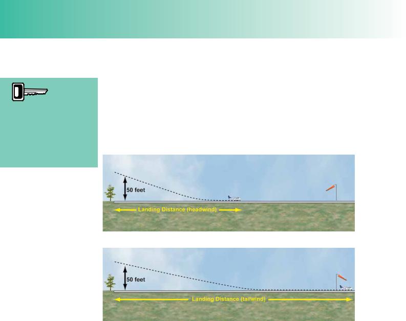
The landing distance required for an aircraft to touch down safely is measured from a point where the aircraft is 50 ft above the threshold to the point at which the aircraft is bought to a full stop. (See Figure 5.1.)
Figure 5.1 Landing Distance is measured from the 50 feet screen height to the point in the landing run where the aircraft is bought to a full stop.
The Landing
Distance is measured
from a point
50 feet above the threshold to the point in the landing run where the aircraft is brought to a full stop. At the screen height, the reference landing
speed, VREF, is assumed to be 1.3 times, VSO .
The 50 feet point is referred to as the landing screen height which is similar to the take off screen height. In the defnition of landing distance, it is assumed that, at the landing screen height, the aircraft is fying at a reference speed, VREF, of at least 1.3 times the aircraft’s stalling speed. VREF gives the aircraft a 30% margin of safety over its stalling speed, in the landing confguration. The stall speed in the landing confguration, with faps lowered, is known as VSO. So, if VSO is 50 knots, VREF is 30% greater than this; that is 65 knots.
Pilots must be aware that although VREF must be at least 1.3 × VSO, if the speed exceeded VREF signifcantly, the landing distance would also be increased by a signifcant margin. It is very important that a pilot should determine the correct approach speed for the conditions, and fy that speed as accurately as possible.
The Landing Distance Available.
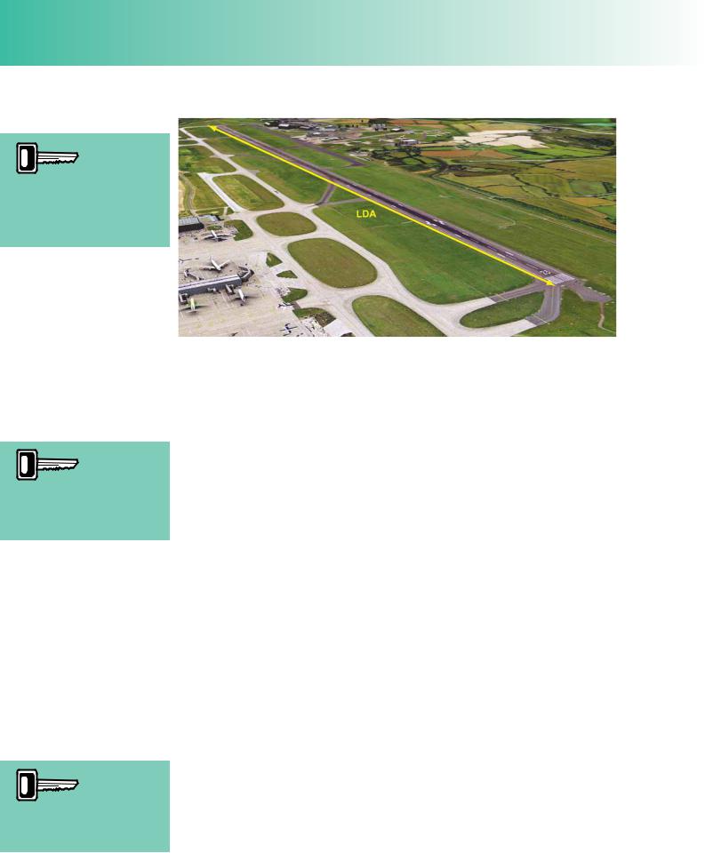
The landing distance that an aircraft requires must not exceed the landing distance available. The landing distance available (LDA) at an airfeld is defned as being the length of runway suitable for landing, taking into account any obstacles in the approach path. Usually, the LDA is the distance from one threshold of the runway to the other. (See Figure 5.2, overleaf.)
In a typical landing, landing faps will have been selected at a suitable point on the approach, and with an airspeed of at least VREF at the 50 feet screen height, the throttle will normally have been closed. By following this procedure, the landing distance required will be kept to a minimum. There are, however, several factors which affect landing distance required, which we will now go on to examine.
VREF must
be achieved, but excess
speed on the
approach will increase the landing distance required.
443
Order: 6026
Customer: Oleg Ostapenko E-mail: ostapenko2002@yahoo.com
Customer: Oleg Ostapenko E-mail: ostapenko2002@yahoo.com
CHAPTER 5: LANDING
The Landing Distance
Available is the length of
runway suitable for landing, taking into account any obstacles in the approach path.
Figure 5.2 The Landing Distance Available (LDA) at an airfield is defined as being the length of runway suitable for landing.
Increased aircraft
mass means increased
momentum, increased VREF and increased landing distance.
A 10% increase in
aircraft mass will increase Landing Distance Required by
10%.
FACTORS AFFECTING THE LANDING.
Aircraft Mass.
Increased mass means that for any given true airspeed, the momentum of the aircraft will also be higher (momentum = mass × velocity). A body’s momentum is often defned as a measure of how much force is required to stop the body moving.
Therefore, the higher an aircraft’s momentum the greater the braking force required to bring the aircraft to rest. As braking force is a function of the aircraft’s brake assembly and is constant for any given set of runway conditions, the greater the aircraft’s mass, the longer will be the period of time during which the braking force must be applied and the longer will be the landing distance required.
As you learnt in Principles of Flight, the greater the aircraft’s mass, the greater will be its weight. You have also learnt that the heavier an aircraft is, the higher will be its stall speed. Therefore, as approach speed needs to be at least 1.3 times VSO, a heavier aircraft will need to approach and touch down at a higher speed than a lighter aircraft. As we mentioned above, momentum = mass × velocity, so the higher speed will impart greater momentum to the aircraft and increase the landing distance required.
Of course, the heavier the aircraft, the greater will be the load acting on the undercarriage rolling assembly and the greater will be the rolling resistance once the aircraft is on the ground. However, this one benefcial effect on landing performance of increased mass or weight does not affect the aircraft anywhere near as much as its increased momentum.
The overall effect of increasing an aircraft’s mass or weight, then, is to increase the landing distance required. As a rule of thumb, we may assume that the landing distance required increases by 10% for every 10% increase in the aircraft’s mass. As a practical guide, for a light aircraft, a 10% increase in mass equates approximately to carrying an extra passenger with luggage.
Reducing mass will, by counter argument, shorten the landing distance required.
444

ID: 3658
Customer: Oleg Ostapenko E-mail: ostapenko2002@yahoo.com
Customer: Oleg Ostapenko E-mail: ostapenko2002@yahoo.com
CHAPTER 5: LANDING
Air Density.
As you have learned from the lift equation in Principles of Flight, Lift = CL½ ρv2 S, lift is directly proportional to air density, ρ. Thus, a decrease in air density will also decrease lift, and, for the reasons given below, lead to an increase in the landing distance required.
Air density, you will recall, decreases with increasing altitude and increasing temperature.
In lower air density, lift is reduced at any given value of true airspeed, v. Consequently, in order to maintain the lift necessary to support the aircraft in steady fight, whether that be straight and level fight or descending fight, such as on the approach to land, an aircraft will have to fy at a higher true airspeed as air density falls. Increased speed increases an aircraft’s momentum, making it more diffcult to stop, and, therefore, also increases, increasing the landing distance required.
You should be aware that it is particularly diffcult for the pilot to detect conditions of low air density. True airspeed, v, must increase to maintain lift when air density falls; indicated airspeed is not affected by changing air density, being a measure of the dynamic pressure, ½ ρv2. As ρ falls, v increases so that the expression, ½ ρv2, remains constant, giving a constant indicated airspeed. Consequently, the pilot will get no clue from his airspeed indicator that air density is low.
In order, then, that a pilot may recognise that air density is low and, thus, be ready and prepared for longer landing distances, he needs to know what the density altitude is of the airfeld from which he is operating. However, if he uses a landing performance graph to calculate the landing distance required for his aircraft, on a given day, he enters pressure altitude and temperature into the graph. As we learnt earlier in the chapter on Take-Off, these two factors used together will account for air density. But if a pilot has no access to landing performance graphs for his aircraft, he may calculate the density altitude of the airfeld using a fight navigation computer. That calculation will tell the pilot whether or not air density is of a signifcantly high or low level. If density altitude is signifcantly different from the pressure altitude of the airfeld, then the manufacturer’s predicted landing performance will have to be modifed.
The drag equation, Drag = CD½ ρv2 S, might suggest that if air density is low, the drag force acting on the aircraft will also be lower. However, although, in conditions of low air density, the aircraft lands at a higher true airspeed, for the reasons explained above, the indicated airspeed, a function of ½ ρv2, will be the same whatever the density, because the reduction in ρ is compensated for by the increase in v. So, the drag force acting on the aircraft during the landing roll will also be the same. Only the higher true airspeed is critical; so the longer landing run is the result solely of the increased momentum of the aircraft.
High humidity also decreases air density. Therefore, if you are operating from a hot, humid, high airfeld, be aware of the effect of the prevailing conditions on your aircraft’s performance. For every 1 000 ft increase in altitude, or 10°C increase in temperature, landing distance will increase by approximately 5%; that is, by a factor of 1.05.
For every
1 000 ft increase in
altitude or
10ºC increase in temperature landing distance required will increase by approx 5%, or a factor of 1.05.
445
Order: 6026
Customer: Oleg Ostapenko E-mail: ostapenko2002@yahoo.com
Customer: Oleg Ostapenko E-mail: ostapenko2002@yahoo.com
CHAPTER 5: LANDING
A headwind will decrease the landing
distance required and a tailwind increase it. When applying wind to landing distance calculations, it is recommended that only 50% of a headwind should be assumed, but 150% of a tailwind.
Wind, Speed and Direction.
The speed and direction of the wind affects landing distance required because of the infuence of head and/or tailwind components, on the ground speed of the aircraft.
Just as for the take-off, it is essential that, when calculating landing distance required, the pilot calculates the strength of the head and/or tailwind component of the wind.
Headwinds will reduce the ground speed for any given indicated air speed and consequently reduce the landing distance required. Tailwinds, on the other hand, will increase ground speed for a given indicated air speed and increase the landing distance required.
Figure 5.3a A landing with headwind.
Figure 5.3b A landing with a tailwind.
Any tailwind component will signifcantly increase the landing distance required, so you must consider very carefully indeed whether a landing can safely be carried out, whenever a tailwind component is present. When calculating the landing distance required, it is highly recommended by the Civil Aviation Authority that you do not use the reported or observed, momentary wind strengths because wind speed and direction can vary greatly over a short time. The recommendation is to use 50% of the headwind component and not less than 150% of the tailwind component. Many performance graphs have these safety factors already applied.
There are two principal reasons why, whenever possible, the fnal approach and landing is made into wind. As you have already learnt, when landing into wind, the ground speed will be lower for a given touchdown airspeed by an amount equal to the speed of the headwind component. In this situation, the landing distance required will be shorter. Furthermore, an approach into wind enables a steeper descent path which, in turn, provides better obstacle clearance performance if required, and will reduce the horizontal distance covered during the round-out and hold-off. Both these considerations reduce the overall landing distance required. (Note, however, that most approaches are fown to a ‘standard’ approach angle, and a steep descent would be used only in unusual circumstances)
446
ID: 3658
Customer: Oleg Ostapenko E-mail: ostapenko2002@yahoo.com
Customer: Oleg Ostapenko E-mail: ostapenko2002@yahoo.com
CHAPTER 5: LANDING
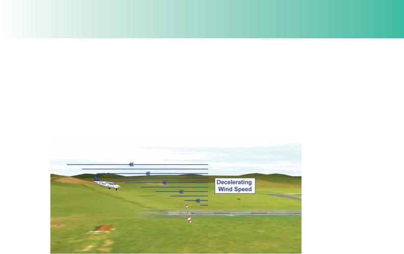
Wind Gradient.
A landing, then, should wherever possible be made into wind. However, in strong and turbulent wind conditions a pilot must be aware of the effect of wind gradient on the performance of his aircraft. As far as the landing is concerned, the term wind gradient can be taken to mean the progressive decrease in wind speed in the lower layers of air near the ground. Wind gradient is most pronounced when a strong, gusting wind is blowing, especially if it is passing over surface obstacles. However, wind gradients may be present in light winds, too.
Figure 5.4 Approaching through a wind gradient.
Consequently, when an aircraft is approaching to land in a pronounced wind gradient, it is fying through layers of decelerating wind speed. (See Figure 5.4.) In this situation, the aircraft may suffer a sudden reduction in indicated air speed, and, therefore, lift, which will cause it to lose height suddenly. Sometimes, in very turbulent conditions, this wind gradient effect may be accentuated by the presence of downdraughts. Obviously, if the increase in vertical descent speed suffered by the aircraft were to occur unexpectedly, the aircraft may undershoot the runway badly and hit the ground frmly, causing damage to its structure and injury to its occupants.
So, if you suspect that wind gradient is present on the approach, increase your approach speed by a suitable amount (seek guidance from your instructor on this) and consider using power to arrest the extra rate of descent as the aircraft starts to sink. Wind gradients are invisible, but may be expected to be signifcant in strong, gusting winds. Often, pilots who have experienced a wind gradient will broadcast that fact over the RT, so listen out carefully for such reports when the wind is strong. NB: Wind gradient is not a performance consideration, but one of handling, since landing performance calculations are based on surface conditions, but it is as well to be aware of such factors, which may affect the point of touchdown.
447
Order: 6026
Customer: Oleg Ostapenko E-mail: ostapenko2002@yahoo.com
Customer: Oleg Ostapenko E-mail: ostapenko2002@yahoo.com
CHAPTER 5: LANDING
Runway Slope.
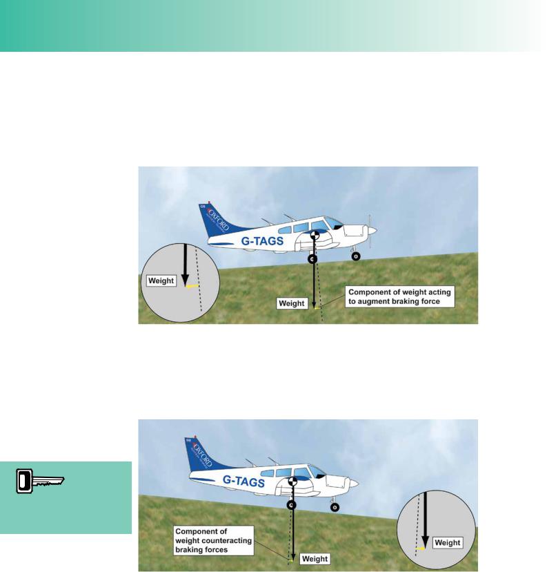
If a landing strip is not horizontal, the landing distance required will be affected.
An uphill slope to a landing strip will decrease the landing distance required because, when rolling uphill, a component of the aircraft’s weight acts rearwards, adding to the braking forces acting on the aircraft. (See Figure 5.5.)
Figure 5.5 Upslope reduces the landing distance required owing to a component of the aircraft’s weight acting backwards to augment braking.
Conversely, a down-hill slope to a landing strip will increase the landing distance required because, when rolling downhill, a component of the aircraft’s weight acts forwards, partially counteracting the braking forces (rolling resistance and application of brakes) acting on the aircraft (See Figure 5.6.)
A down slope increases
the landing distance
required by 5% for every 1% of slope.
Figure 5.6 Downslope increases the landing distance required owing to a component of the aircraft’s weight acting forwards, acting against the braking force.
For every 1% of down-slope, the landing distance required is increased by approximately 5%; in other words, landing distance is increased by a factor of 1.05. Bear in mind that this is the factor which should be applied to the landing distance, that is, from a height of 50 feet above the landing strip. The increase in the landing run will be proportionally greater.
448

ID: 3658
Customer: Oleg Ostapenko E-mail: ostapenko2002@yahoo.com
Customer: Oleg Ostapenko E-mail: ostapenko2002@yahoo.com
CHAPTER 5: LANDING
Pilots should treat as a “bonus” any advantage gained from landing on an up-slope or taking off on a down-slope, and not include any allowance for these two latter circumstances in their performance calculations.
Runway Surface.
Most landing performance graphs assume that the aircraft is landing on a paved hard surface. If the surface of the landing strip is not paved, corrections must be applied to the calculated landing distance required.
Many small airfelds have grass runways. Grass will increase the rolling resistance of the wheels, but, more importantly, will reduce the friction between the tyres and runway. This means that the brakes cannot be applied as frmly as on a paved surface, otherwise the wheels will lock and slip. Consequently, assuming that the wheel brakes are always used, landing on a grass surface will increase the landing distance required.
Dry grass of up to 8 inches (20 cm) in height will increase the landing distance by 20% or a factor of 1.2, if brakes are used. However, assuming that brakes are not used, landing on grass will shorten the landing run and, thus, reduce the overall landing distance required, compared to landing on an asphalt surface without brakes.
A wet surface, either grass or paved, will reduce the friction between the wheels and the surface, preventing effective braking and increasing the landing distance required.
The following approximate factors will help you estimate the effect of different surfaces on landing distance required:
•On a wet hard surface the landing distance will be increased by 15%, a factor of 1.15.
•Short dry grass will increase the landing distance by 15%, a factor of 1.15, assuming that brakes are used.
•Wet grass will increase landing distance by 35%, a factor of 1.35.
•If there is surface snow or slush, the landing distance will increase by approximately 25%, which is a factor of 1.25.
Use of Flap.
As you have learnt elsewhere, both in Performance and Principles of Flight, the deployment of fap increases the total drag acting on an aircraft, thereby decreasing the lift/drag ratio. Both these effects of fap infuence the landing distance required.
The extent to which the use of fap increases total drag depends on the angle of fap selected.
The drag equation (Drag = ½ CD½ ρv2 S) shows us that drag is directly proportional to CD. CD, as you have learnt, is a measure, among other things, of aerofoil profle and angle of attack. Lowering fap modifes the profle of the aerofoil, and will therefore alter the value of CD. In general, then, we may conclude that drag is proportional to the amount of fap selected. Furthermore, because lift must remain
A wet paved
surface will increase
the landing
distance required by 15%, dry grass up to 20 cm by 20%, wet grass up to 20 cm by 35% and soft ground, snow or slush by 25%.
449
Order: 6026
Customer: Oleg Ostapenko E-mail: ostapenko2002@yahoo.com
Customer: Oleg Ostapenko E-mail: ostapenko2002@yahoo.com
CHAPTER 5: LANDING
constant for a given aircraft on a given fight (ignoring the change in weight resulting from fuel consumption), as drag increases, the lift/drag ratio will decrease, and, in the approach at any given power setting, the descent angle will be steeper.
If the pilot selects a large angle of fap, then, the increase in drag will be large, and, at a given power setting on the approach, or on a glide approach, the descent angle will be steeper. The steeper descent angle, together with the high drag during the ground run, will shorten the landing distance required. The steeper descent angle will, of course, also improve obstacle clearance performance.
In addition, lowering fap will reduce the aircraft’s straight fight stalling speed; so both VSO and the 50 feet airspeed VREF will be lower, resulting in a decrease in the aircraft’s momentum and a consequent further shortening of the landing run.
It follows, then, that the smaller the angle of fap selected, the lower will be the drag acting on the aircraft, the better the lift/drag ratio, the shallower the descent angle, the lower the obstacle clearance performance, the higher the airspeeds VSO and VREF, and, consequently, the longer the landing distance required.
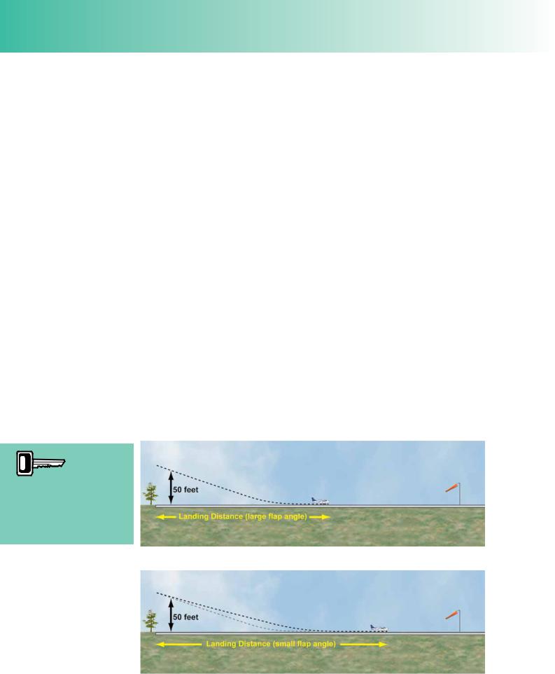
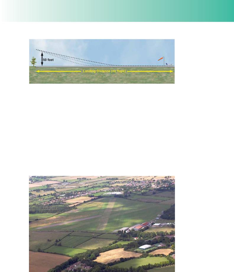
Figures 5.7, 5.8 and 5.9 depict the different angles of descent on the approach and the differences in the landing distance required for an approach fown with a large angle of fap, a small angle of fap, and no fap, respectively. In each case, we have assumed that the aircraft achieves the 50 feet screen height correctly. Notwithstanding these considerations, you should bear in mind that the approach angle will normally be kept constant, but with speed reduced in stages as fap is lowered to take advantage of the shorter ground roll. You can see, however, that if an approach into a feld were necessary, following an engine failure, the use of fap would increase the aircraft’s obstacle clearance capability.
The use of flap on final
approach and landing
reduces VREF and landing distance required, and gives
a steeper approach path with a lower nose attitude which improves forward vision.
Figure 5.7 A landing with a large angle of flap selected.
Figure 5.8 A landing with a small angle of flap selected.
450
ID: 3658
Customer: Oleg Ostapenko E-mail: ostapenko2002@yahoo.com
Customer: Oleg Ostapenko E-mail: ostapenko2002@yahoo.com
CHAPTER 5: LANDING
Figure 5.9 A landing with no flap selected.
It is always advisable for the pilot to land using the manufacturer’s recommended landing fap setting for the aircraft.
The extension of fap, generally, requires a lower nose attitude for a given speed, which has the added advantage of giving the pilot a better view of the landing area during the approach. However, the effect of fap may vary signifcantly from one aircraft to another.
Calculations of Landing Distance Required.
Landing performance data may be presented in the form of tables or graphs. Tables are straight forward to interpret and if you have followed the examples we have used in the previous sections, you will have no trouble extracting data from a landing distance required table.
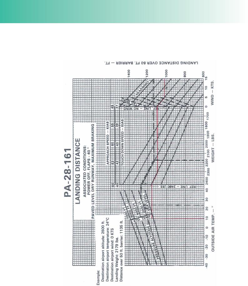
The most common form in which landing performance data is to be found, in an aircraft’s Flight Manual or Pilot’s Operating Handbook, is the landing distance graph, such as the one for the PA-28-161 Warrior depicted in Figure 15.10, overleaf.
Figure 5.9a An airfield with a grass runway. By kind permission of David Henson
451
Order: 6026
Customer: Oleg Ostapenko E-mail: ostapenko2002@yahoo.com
Customer: Oleg Ostapenko E-mail: ostapenko2002@yahoo.com
CHAPTER 5: LANDING
Figure 5.10 Landing distance graph showing example calculation.
452