

ppl_05_e2
.pdfID: 3658
Customer: Oleg Ostapenko E-mail: ostapenko2002@yahoo.com
Customer: Oleg Ostapenko E-mail: ostapenko2002@yahoo.com
CHAPTER 14: FLIGHT AND GROUND LIMITATIONS
Figure 14.10 In the descent, the flight forces are in equilibrium (simplified diagram).
In the dive, the angle of attack will have been very small: about 1°.
Figure 14.11 The relationship between angle of attack and CL is linear until just before the stall.
We also know that the relationship between angle of attack and CL is linear, until just below the stalling angle of attack (See Figure 14.11).
As lift is a little less than weight in the dive, CL will have to be increased by a factor of just under 4 in order to pull out of the dive by applying a load factor of 3.5, (3.5g) The pilot will, thus, ease the control column rearwards, increasing his angle of attack from 1° to just under 4°.
This is not a very great increase.
It is easy to see, therefore, that unless the pilot is very careful in his application of backward pressure on the control column, CL may easily rise to a level where the lift force exceeds that which gives the maximum permissible load factor. Even if the maximum permissible load factor for the aircraft were 4.4 (typical of a Utility Category
337

Order: 6026
Customer: Oleg Ostapenko E-mail: ostapenko2002@yahoo.com
Customer: Oleg Ostapenko E-mail: ostapenko2002@yahoo.com
CHAPTER 14: FLIGHT AND GROUND LIMITATIONS
Stall speed
increases in a turn and in the recovery
from a dive because of the increased load factor.
aircraft certifed for “limited” aerobatics) an increase in angle of attack from 1° to 5° , still only a very small change, would overstress the aircraft.
However, the risk of damaging his aircraft by pulling the control column back too far and exceeding the load factor is not the only risk to which the pilot is exposed. As you have already learned, with increasing load factor, the stalling speed increases, too; (Stall Speed = straight fight stall speed × stttttttttttttttttLoad Factor). At a load factor of
3.5, the stall speed will already be almost twice as high as in straight and level fight. So if the aircraft’s stall speed from straight and level fight were 52 knots, the aircraft would stall at around 100 knots during a 3.5g manoeuvre. Stalling at such a high speed is a very real danger, especially if the aircraft is near to the ground. So, always allow plenty of time and height to pull out of a dive, and recover gently.
THE MANOEUVRE ENVELOPE (THE V-n DIAGRAM).
The limiting load factor and limiting speeds which must be allowed for during straight fight and manoeuvres are represented graphically by what is called the manoeuvre envelope, or V-n diagram (where V stands for velocity and n stands for load factor).
Separate manoeuvring envelopes can be produced for each confguration of an aircraft. (The word confguration refers to whether the aircraft is clean, or has faps or undercarriage extended etc.) A typical clean manoeuvring envelope for a light aircraft, an example of which is represented at Figure 14.12, usually contains the following critical airspeeds:
•the stall speed from straight and level fight (where load factor = 1), VS
•the maximum manoeuvring speed, VA
•the maximum normal operating speed, VNO
•the never-to-exceed speed, VNE
•Sometimes, the design dive speed, VD, may be shown, too.
Limiting Speeds and Loads.
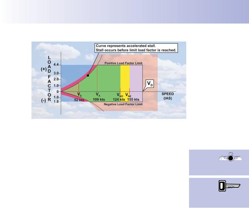
The horizontal axis of the graph in Figure 14.12 shows indicated airspeed, while the vertical axis indicates load factor. The load factors above the horizontal axis are positive, and those below the horizontal axis are negative. Figure 14.12 represents an aircraft of the utility category certifed for a limiting positive load factor of + 4.4 and a limiting negative load factor of -1.8. (The categorisation of aircraft is covered in some detail in the ‘Aeroplanes (General)’ volume of this series.)
Flight outside the manoeuvre envelope, in the regions to the left of the accelerated stall curve is not possible because the wings will be stalled. The curve above the
horizontal axis represents the accelerated stall speeds under various load factors; (that is: of VS × stttttttttttttttload fac or). For instance, the stall speed from straight and level
fight, where the load factor is 1, is given as 52 knots, whereas under a load factor of
4.4, the aircraft will stall at 109 knots. 109 knots is also shown in the manoeuvring envelope as the maximum manoeuvring speed, VA.
At low speeds, the stall is normally induced by full backward movement on the control column which produces a full upwards defection of the elevator. As you see from
Figure 14.12, at low speeds the aircraft will stall before the positive limit load factor
338
ID: 3658
Customer: Oleg Ostapenko E-mail: ostapenko2002@yahoo.com
Customer: Oleg Ostapenko E-mail: ostapenko2002@yahoo.com
CHAPTER 14: FLIGHT AND GROUND LIMITATIONS
Figure 14.12 Representative manoeuvre envelope for a light aircraft showing limiting speeds and load factor.
is reached. This is the case for speeds up to VA, the maximum design manoeuvring speed.
But beyond VA, the positive limit load factor may be reached before the aircraft stalls. The manoeuvre envelope, then, illustrates graphically that full backwards movements of the control column must not be made above VA. In fact, no maximum defections of the control surfaces or abrupt movements of the control column should be made when the aircraft is fying at speeds above VA. However, bearing that precaution in mind, the aircraft may be operated safely above this speed.
VNO, the maximum normal operating speed, marks the upper speed limit in turbulent air. VNO must not be exceeded unless conditions are smooth. VNE marks the airspeed which should never be exceeded, or structural distortion of the airframe is likely to occur.
Structural failure is almost certain if the design dive limit, VD , is exceeded. VD is the maximum speed considered when assessing the structural strength of an aircraft. In general, VNE is set about 10% lower than VD.
If you fnd yourself fying in atmospheric conditions which are very turbulent, you should consider maintaining your airspeed at or below VA, and avoid any abrupt control movements, in order to prevent excessive fight loads damaging the structure of your aircraft.
The Gust Envelope.
Strong vertical gusts may impose severe loads on the wing structure by inducing rapid changes in angle of attack (and, thus, CL), which generate associated changes in the magnitude of the lift force. The greater the aircraft’s speed, the greater will be the loads on the airframe induced by the gusts.
Aircraft designers must, therefore, include a safety factor in the design of aircraft structures to allow for unexpected gust loads. The manoeuvring envelope for an aircraft which takes into account gust loading is sometimes referred to as a gust envelope. The gust envelope often takes the form of an overlay to the normal
Above VA, the 

 positive limit
 load factor may
be reached
before the aircraft stalls.
VNO marks
the upper limit of the normal
operating
speed range and should not be exceeded in turbulent air.
339
Order: 6026
Customer: Oleg Ostapenko E-mail: ostapenko2002@yahoo.com
Customer: Oleg Ostapenko E-mail: ostapenko2002@yahoo.com
CHAPTER 14: FLIGHT AND GROUND LIMITATIONS
manoeuvring envelope diagram, having the effect of reducing the lateral and vertical extents of the normal envelope.
Many aircraft designers establish a maximum turbulence penetration speed, VB, which assumes that a light aircraft at cruise speed will meet varying vertical gust components of up to 50 feet/second. For most light aircraft, there will probably not be a great difference between maximum turbulence penetration speed, VB, and maximum manoeuvring speed, VA. So, if no VB is specifed for the aircraft that you fy regularly, do not fy above VA in severe turbulence.
Flap Limiting Speed.
Flaps are designed, amongst other things, to reduce take-off and landing distances. Lowering fap increases a wing’s CL, generating equivalent lift at lower speeds, thus enabling the aircraft to approach to land at the lowest speed possible. Flaps also, of course, increase drag and permit suitably steep approach paths on landing. The
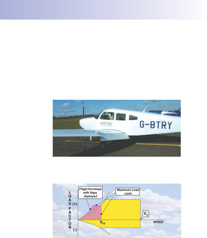
Figure 14.13 The flaps and their operating mechanism are not designed to withstand the aerodynamic loads which occur at high cruising speed.
fap surfaces, their operating mechanism and attachment points to the structure are not designed to withstand the aerodynamic loads which occur at cruising airspeeds and above.
Figure 14.14 Manoeuvre envelope with flaps extended.
A manoeuvre envelope can be drawn for an aircraft with faps extended. Figure 14.14
340
ID: 3658
Customer: Oleg Ostapenko E-mail: ostapenko2002@yahoo.com
Customer: Oleg Ostapenko E-mail: ostapenko2002@yahoo.com
CHAPTER 14: FLIGHT AND GROUND LIMITATIONS
shows how a “faps extended” manoeuvring envelope might look. You will see that the bounds of the faps extended envelope are markedly reduced in comparison to the clean confguration envelope. The load factor limits are lower and maximum permissible speed also much reduced. The critical speed which must never be exceeded with faps extended is termed VFE, (Velocity Flaps Extended).
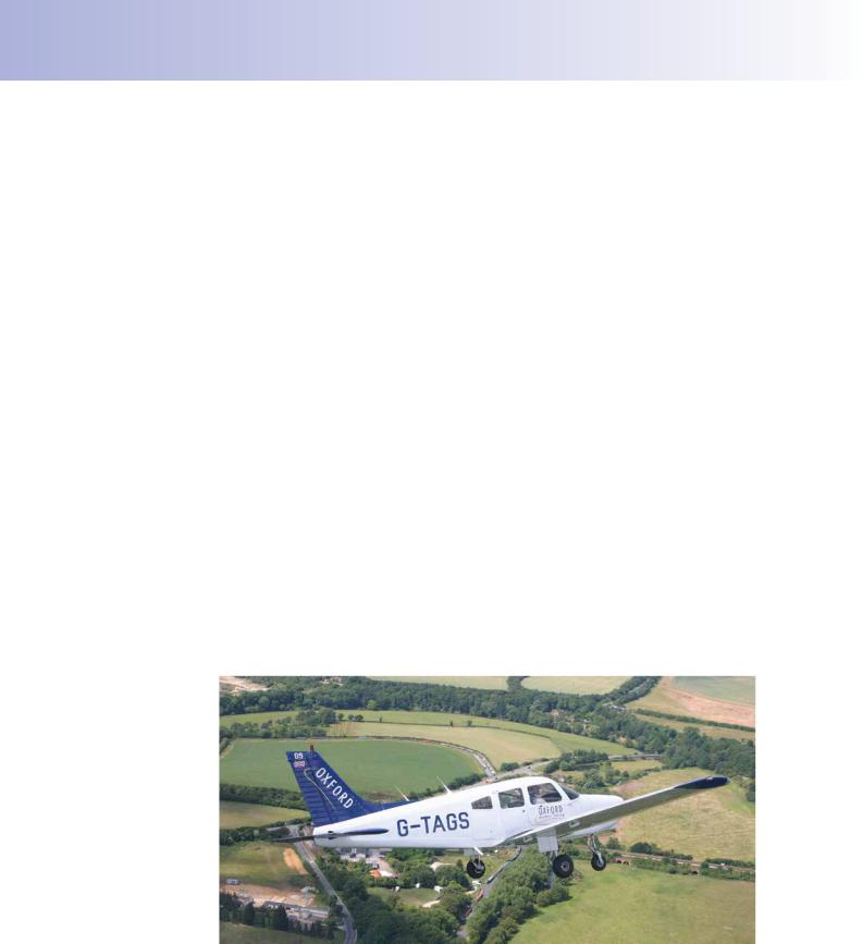
Landing Gear Limiting Speeds.
The landing gear (or undercarriage) will normally be retracted as soon as safely possible after take-off, in order to reduce drag and increase the climb gradient.
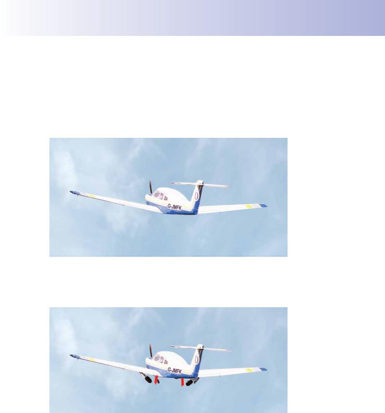
Figure 14.15 Gear is retracted when safely airborne.
There is normally no requirement for the landing gear to be operated or extended during normal cruising fight. Therefore the size and strength of the gear mechanism is designed solely to meet landing and take-off requirements. Consequently, there are normally two speed limitations for the landing gear, depending on system design.
Figure 14.16 Gear doors are not able to withstand large aerodynamic loads.
VLO is the landing gear operating speed. At or below VLO, it is both safe to retract and extend the landing gear. On certain types of aircraft, it is permissible to lower the gear and fy with it extended at a higher airspeed than that at which it may be retracted. If this is the case, a maximum operating speed with the gear extended is specifed VLE. But before the landing gear is retracted, speed must be at or below VLO.
341
Order: 6026
Customer: Oleg Ostapenko E-mail: ostapenko2002@yahoo.com
Customer: Oleg Ostapenko E-mail: ostapenko2002@yahoo.com
CHAPTER 14: FLIGHT AND GROUND LIMITATIONS
The flap operating
speed range is indicated on
the ASI by the white arc.
When the landing gear is operated, the gear doors must open frst to allow the gear to move up or down before closing again. The purpose of the doors is merely to streamline the area of the undercarriage bay. Doors are not designed to withstand the aerodynamic loads to which they would be subjected at high indicated airspeeds; consequently VLO is usually lower than VLE.
LIMITING |
SPEEDS ON |
THE |
||
AIRSPEED INDICATOR. |
|
|||
In |
order |
to |
assist the pilot to take |
|
into account the various speed limits |
||||
imposed |
on |
his aircraft’s structure, |
||
the |
more |
common limiting |
speeds |
|
are marked on an aircraft’s airspeed |
||||
indicator by coloured arcs, as depicted |
||||
in Figure 14.17. |
|
|||
• The white arc extends from the |
||||
|
stall speed with faps extended, in |
|||
|
the landing confguration (full-fap, |
|||
|
maximum all-up weight, gear down, |
|||
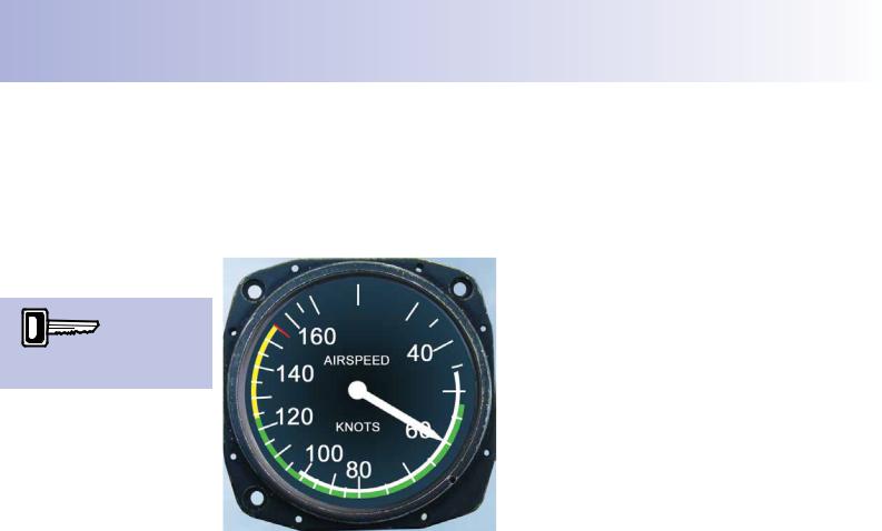
Figure 14.17 ASI. |
power-off, wings level), to |
the fap |
||
limiting speed, VFE. |
|
|||
|
|
|||
•The green arc extends from the clean, straight fight, 1g stall speed, VS (maximum all up weight, faps-up), to the maximum normal operating
speed, VNO. The green arc represents the normal operating speed range for the aircraft. Flight at speeds within the green arc should be safe in all conditions.
•The yellow arc begins at VNO and stretches to the velocity never-to-exceed, VNE. The yellow arc marks the caution range. The aircraft should be operated in this speed range in smooth conditions only.
•VNE is marked by a short red radial line at the top end of the yellow arc.
GROUND LOADS.
After landing, the loads acting on the aircraft’s structure are distributed differently from the way they are distributed in fight.
Consider, for instance, the case of the wing surface material, or skin, which is strong in tension but weak in compression. In fight, the wing bears the weight of the whole aircraft. When in the air, the skin on the under-surface of the wing is heavily loaded in tension and the skin of the upper surface is under compression, and may appear wrinkled. On the ground, the situation is reversed: the wing carries its own weight; its lower skin is under compression and its upper skin under tension
At the moment of touch-down, the wings are still developing lift equal, or almost equal, to weight; but additional shock-loads are imposed on the aircraft by the impulse of the frst contact with the ground which causes the aircraft to decelerate abruptly in
342
ID: 3658
Customer: Oleg Ostapenko E-mail: ostapenko2002@yahoo.com
Customer: Oleg Ostapenko E-mail: ostapenko2002@yahoo.com
CHAPTER 14: FLIGHT AND GROUND LIMITATIONS
the vertical plane. A heavy landing imposes shock loads on the wings as well as the undercarriage. This type of shock load which may exceed 3g and which will be both positive and negative. A shock load, or impulse, of 3g transmitted to point locations may cause structural damage, whereas a gradually applied load of 3g over the whole aircraft structure will not. Following a suspected heavy landing, an engineer may fnd evidence of damage by examining the upper surface of the wing, near centre span where the bending moments will have been at their most powerful.
On the ground, then, without any signifcant forward speed, the aircraft’s structure must support its own weight without any help from aerodynamic lift. In this situation, the weight of the various components making up the aircraft are transmitted from component to component and eventually through to the undercarriage and tyres.
Consider a typical light aircraft, weighing 2000 lbs (907 kg or, more scientifcally, 8900 Newtons), whose wing area is 170 ft2 (15.8 m2), in two different situations: in fight and on the ground. In steady, straight fight, the wing loading (Weight/Wing
Area) is 12 lbs/ft2 (or 563 Newtons/ m2), whereas, on the ground, the tyres will be supporting a load of around 1684 lbs/ft2, (12 lbs/in2 or 28 Newtons/cm2).
During taxying manoeuvres, thrust and braking loads are superimposed on the ground loads. These loads, occurring along the longitudinal axis, normally arise as a result of take-off, landing and braking, which means that the undercarriage must be strong, but with weight kept to a minimum, particularly as it is of no use to us once airborne. The aircraft designer, then, must produce a strong, lightweight undercarriage whilst maintaining minimum safety standards.
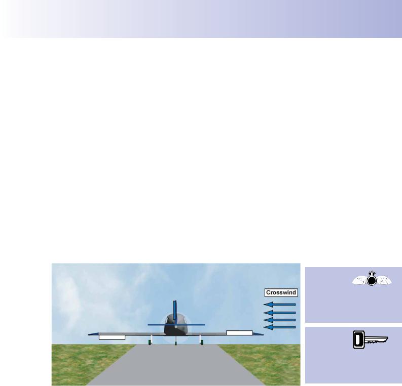
When taking
off in a crosswind,
keep straight with rudder and apply sufficient into wind aileron to prevent the upwind wing from lifting first.
Crosswind limits
for take-off are determined
by the
manufacturer and published in the Pilot’s Operating Handbook and Checklist.
Figure 14.18 Side loads are imposed on the undercarriage during crosswind takeoffs and landings.
Side Loads on the Undercarriage.
Excessive side loads on the undercarriage, can cause damage to both undercarriage and tyres. Side loads can be imposed on the undercarriage through taxying the aircraft too fast or attempting to turn the aircraft through too tight an angle, but it is take-off and landing, particularly in crosswinds, which impose the greatest side loads. This is one of the reasons why limits are set on the maximum permissible crosswind for take-off and landing.
Initially, during a crosswind take-off, the weight of the aircraft on the undercarriage will help to resist any sideways movement. But as speed increases and the wings
343
Order: 6026
Customer: Oleg Ostapenko E-mail: ostapenko2002@yahoo.com
Customer: Oleg Ostapenko E-mail: ostapenko2002@yahoo.com
CHAPTER 14: FLIGHT AND GROUND LIMITATIONS
start to generate lift, the into-wind wing may start to rise which will cause a side load on the undercarriage.
A lifting wing may be counteracted throughout the take-off run by applying a measure of aileron into wind in order to keep the wings level while maintaining direction by application of opposite rudder to resist the aircraft’s tendency to weathercock into wind.
LANDING WITH CROSSWIND.
Not only taking off but also landing with a crosswind can cause excessive side loads on an aircraft undercarriage, therefore a maximum crosswind limit for landing will also be imposed. It is important that the side loads are kept to a minimum at the point of touchdown, which is one reason why you will learn various crosswind landing techniques during fight training.
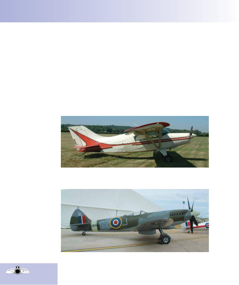
Figure 14.19 Maule M-7.
Tail Wheel Aircraft.
When taxying
a tail wheel aircraft the
forward visibility is restricted.
Figure 14.20 Spitfire FR XVIIIe.
Throughout the various chapters of this Principles of Flight book, the aircraft to which we have referred to illustrate the many different topics we have covered have, for the most part, possessed tricycle undercarriages. Tricycle undercarriage aircraft now represent by far the majority of aircraft in service. However, many tail wheel aircraft, or tail-draggers as they are popularly known, are still fown. (See Figures 14.19 & 14.20.)
344

ID: 3658
Customer: Oleg Ostapenko E-mail: ostapenko2002@yahoo.com
Customer: Oleg Ostapenko E-mail: ostapenko2002@yahoo.com
CHAPTER 14: FLIGHT AND GROUND LIMITATIONS
In the air both types are fown by the pilot using the same techniques but, on the ground, their handling characteristics are quite different.
The tail wheel aircraft has its Centre of Gravity (C of G) behind the main wheels. This C of G position tends to make the aircraft unstable during ground movement. If a tail wheel aircraft were to start to swing during the take-off run, the amplitude of the swing would tend to increase, and, unless carefully controlled, could lead to the aircraft entering a ground loop. Tail wheel pilots soon learn that any swing on take-off must be prevented or promptly corrected by use of rudder.
DESIGN LOADS AND SAFETY FACTORS.
Having looked in some detail at the speed, weight and loading limitations to which aircraft are subjected, it is may be of interest to conclude this chapter by considering how a designer approaches the issue of load limits.
Aircraft designers are able to calculate the effects that fight forces will have on an aircraft’s structure, during the initial conception of a new aircraft. Manufacturers, therefore, design and construct an aircraft so that it has adequate strength to withstand the loads which it is expected to bear in fulflling the role for which it is designed.
You have already learned that even a touring aircraft may be stressed to bear positive loads which are up to 3.8 times the magnitude of its maximum operating weight. There is a regulatory requirement that Normal Category aircraft must be strong enough to bear a positive load factor of at least 2.5 (2.5g). Aircraft are stressed to withstand these load factors (referred to by such terms as positive limit load factors) as part of their normal operating envelope.
Aerobatic aircraft will be stressed to bear a typical positive load factor of 6, and a negative load factor of -3 or more. (The Extra 300 is stressed to +10/-10!). Again these are designed limit loads. A military fghter aircraft may well be designed to withstand positive manoeuvres of up to 12g. (The Typhoon and the F- 22 both have design load factor limits of +9 and -3)
But despite the best forecasts of the designer, and making all the appropriate allowances for unexpected loads due to gusts, heavy landings etc, there still remain a number of incalculable circumstances against which designers have to guard. Obviously, if every eventuality were catered for, aircraft structures would become far too heavy; however, to allow for the unexpected, factors are applied to the highest loads envisaged during normal fight conditions.
These factors are called safety factors.
Aircraft are designed up to a level of structural strength defned by what is called the ultimate design load. Damage to the aircraft’s structure, in the form of component deformation, will be likely at some point between the prescribed maximum load limits and the ultimate design load; but at the ultimate design load or beyond, the aircraft’s structure is almost certain to fail.
The maximum design load will normally be increased by a safety factor of at least 1.5 over and above the aircraft’s prescribed maximum load limits (the load limits of the manoeuvre envelope). Thus, an aircraft of the Normal Category whose positive load factor limit may be set at 3.8 should be able to absorb a load factor of at least +5.7 before the structure fails.
345
Order: 6026
Customer: Oleg Ostapenko E-mail: ostapenko2002@yahoo.com
Customer: Oleg Ostapenko E-mail: ostapenko2002@yahoo.com
CHAPTER 14: FLIGHT AND GROUND LIMITATIONS
Aircraft components and complete airframes are tested by being subjected to repeated load reversals in test rigs in order to simulate the thousands of fying hours that an aircraft type might be expected to log in a normal in-service life. During the testing of a new aircraft type, the magnitude of the load reversals applied to the aircraft is increased progressively. If the structure fails prematurely, components are redesigned up to the calculated maximum design load, which is the design load limit of the manoeuvre envelope multiplied by a safety factor. When this maximum design load has been established and tested to the satisfaction of the designers, loading continues until a major failure occurs. The load at which failure occurs is the ultimate load for the aircraft type and model.
From this testing, safe life periods are published for structural components, especially wing-spars, which determine the minimum number of fying hours which are statistically likely to elapse before major failure occurs.
It is interesting to note that most load-bearing metal components on an aircraft suffer from fatigue through continual load reversal, and will be given a defnite safe life.
The greater the amplitude of the reversals, and the more frequently they occur, the shorter will be the fatigue life of the component. Wooden components, however, notably the wooden spars of vintage aircraft, provided that they remain within their elastic limit have an indeterminate fatigue life. Wooden components are more likely to fail because of decomposing adhesive bonding, or even because of termite or rodent damage, rather than through fatigue. The wing spars on modern aircraft constructed of certain modern composite materials such as carbon fbres, bound together by epoxy resins, have the same indeterminate life as wooden spars.
Aircraft components made of wood or composite materials will fail, though, in the same way as metal components, if they exceed their design limit load. So, whatever the aircraft you fy, design load factors and airspeed limitations must be respected.
346