

ppl_05_e2
.pdfID: 3658
Customer: Oleg Ostapenko E-mail: ostapenko2002@yahoo.com
Customer: Oleg Ostapenko E-mail: ostapenko2002@yahoo.comCHAPTER 3: CLIMB QUESTIONS
5.The best rate of climb is achieved:
a.when fying at the speed for maximum excess thrust available
b.when climbing into wind
c.when fying at VX
d.when fying at the speed for maximum excess power available.
6.Climbing at VX will achieve:
a.the best time to height
b.the greatest increase in altitude in a given time
c.the maximum angle of climb
d.the maximum horizontal distance for a given vertical distance
7.One effect of climbing an aircraft with fap selected would be:
a.an improved climb performance
b.a decreased co-effcient of drag
c.a decreased co-effcient of lift
d.a reduced rate and angle of climb
8.Increasing the mass (and, therefore, the weight) of an aircraft will:
a.decrease the rate and angle of climb
b.increase the rate and angle of climb
c.increase the rate of climb and decrease the angle of climb
d.decrease the rate of climb and increase the angle of climb
9.Climbing at VY will achieve:
a.the maximum angle of climb
b.the greatest increase in altitude in a given period of time
c.the maximum increase in height in the shortest horizontal distance
d.the best obstacle clearance performance
413

Order: 6026
Customer: Oleg Ostapenko E-mail: ostapenko2002@yahoo.com
Customer: Oleg Ostapenko E-mail: ostapenko2002@yahoo.com
CHAPTER 3: CLIMB QUESTIONS
10.An aircraft cruising at a pressure altitude 2 000 feet is cleared to climb to a pressure altitude 8 000 feet. Using the table, calculate the time taken in minutes, the fuel used in gallons and the horizontal distance fown in the climb, assuming zero wind.
FUEL, TIME and DISTANCE TO CLIMB
Associated Conditions
Weight: 2440 Lbs, Flaps: 0°, Full Throttle
Mixture leaned as per maker’s instructions 79 Knots, indicated airspeed. No Wind
FOR |
TRAINING |
ONLY |
|
PURPOSES |
|
Pressure Altitude |
|
|
From Sea Level |
|
|
ISA Temp °C |
Time in |
Fuel used |
|
|
|
Feet |
|
Distance |
|||
|
Minutes |
Gallons |
|
||
|
|
|
|
||
Sea Level |
15 |
0 |
0 |
|
0 |
1000 |
13 |
2 |
0.4 |
|
2 |
2000 |
11 |
4 |
0.7 |
|
5 |
3000 |
9 |
6 |
1.5 |
|
8 |
4000 |
7 |
8 |
1.8 |
|
11 |
5000 |
5 |
10 |
2.0 |
|
14 |
6000 |
3 |
13 |
2.5 |
|
17 |
7000 |
1 |
16 |
3 |
|
21 |
8000 |
-1 |
19 |
4 |
|
27 |
9000 |
-3 |
24 |
5 |
|
34 |
10 000 |
-5 |
30 |
6 |
|
42 |
Figure 3.25 Climb performance fgures in tabular format.
a.19 minutes, 4 gallons, 27 miles
b.23 minutes, 4.07 gallons, 32 miles
c.15 minutes, 3.3 gallons, 22 miles
d.4 minutes, 0.7 gallons, 5 miles
11.The lift produced by the wing of an aircraft in a steady climb maintaining a constant indicated airspeed will be:
a.less than weight
b.greater than weight
c.equal to weight
d.independent of weight
414

ID: 3658
Customer: Oleg Ostapenko E-mail: ostapenko2002@yahoo.com
Customer: Oleg Ostapenko E-mail: ostapenko2002@yahoo.comCHAPTER 3: CLIMB QUESTIONS
12.How will an aircraft’s maximum rate of climb be affected by selecting take-off fap?
a.The maximum rate of climb will increase
b.The maximum rate of climb will not be affected
c.The maximum rate of climb will remain the same provided that the pilot chooses an appropriate power setting
d.The maximum rate of climb will decrease
13.What effect will a decreasing headwind component have on the best achievable angle of climb.
a.The angle of climb will decrease
b.The angle of climb will steepen
c.The angle of climb will remain constant at all values of headwind component.
d.The angle of climb is independent of the value of headwind component.
Question |
1 |
2 |
3 |
4 |
5 |
6 |
7 |
8 |
9 |
10 |
11 |
12 |
|
|
|
|
|
|
|
|
|
|
|
|
|
|
|
Answer |
|
|
|
|
|
|
|
|
|
|
|
|
|
|
|
|
|
|
|
|
|
|
|
|
|
|
|
Question |
13 |
|
|
|
|
|
|
|
|
|
|
|
|
|
|
|
|
|
|
|
|
|
|
|
|
|
|
Answer |
|
|
|
|
|
|
|
|
|
|
|
|
|
The answers to these questions can be found at the end of this book.
415
Order: 6026
Customer: Oleg Ostapenko E-mail: ostapenko2002@yahoo.com Customer: Oleg Ostapenko E-mail: ostapenko2002@yahoo.com
416
ID: 3658
Customer: Oleg Ostapenko E-mail: ostapenko2002@yahoo.com
Customer: Oleg Ostapenko E-mail: ostapenko2002@yahoo.com
CHAPTER 4
EN-ROUTE PERFORMANCE
417

Order: 6026
Customer: Oleg Ostapenko E-mail: ostapenko2002@yahoo.com
Customer: Oleg Ostapenko E-mail: ostapenko2002@yahoo.com
CHAPTER 4: EN-ROUTE PERFORMANCE
418
ID: 3658
Customer: Oleg Ostapenko E-mail: ostapenko2002@yahoo.com
Customer: Oleg Ostapenko E-mail: ostapenko2002@yahoo.com
CHAPTER 4: EN-ROUTE PERFORMANCE
INTRODUCTION.
This chapter deals with the performance of an aircraft in the en-route phase of fight.
The en-route phase of fight includes climb to cruising altitude, the cruise itself, and the initial descent. Chapter 3 covered the climb in detail, so, in this chapter, we will deal with the cruise and the initial descent. We begin with the cruise.
Cruise performance is generally measured in terms of an aircraft’s range, fuel consumption and endurance. But, frst of all, we will consider the forces acting on an aircraft in the cruise, assuming straight and level fight, at constant speed.
FORCES ACTING ON AN AIRCRAFT IN THE CRUISE.
You learnt in Chapter 9 of the Principles of Flight section of this volume, that, for an aircraft to be in steady, straight fight, all forces acting on the aircraft, and any turning moments to which the aircraft is subjected, must balance one another. In other words, for steady, straight fight, the forces, and moments acting on the aircraft must be in a state of equilibrium.
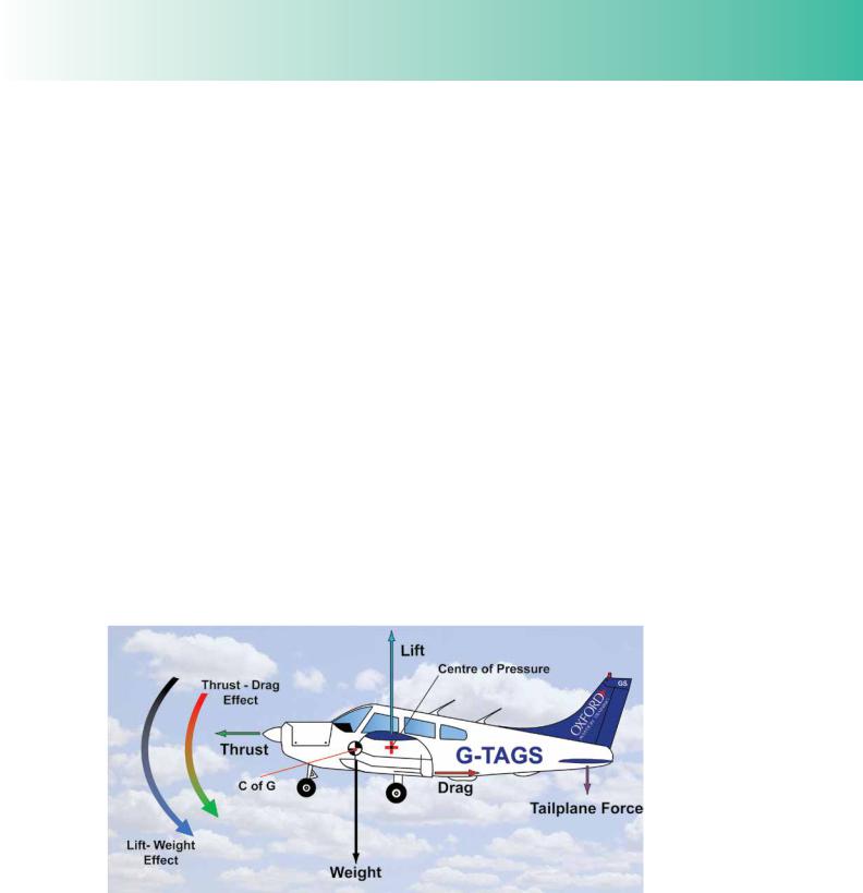
Chapter 9 explained that because of the disposition of the principal fight forces of thrust, drag, lift and weight, and the movement of their lines of action during fight, the turning moments produced by the thrust-drag force couple and the lift-weight force couple are very rarely in balance. For instance, in Figure 4.1, below, both the thrust-drag and lift-weight couples reinforce each other to give a nose-down pitching moment. Consequently, in this case, a downwards-acting force must be generated by the tailplane or stabilator to achieve equilibrium. (See Figure 4.1.)
Figure 4.1 A tailplane force is required to balance the Thrust-Drag and Lift-Weight Couples.
The magnitude and direction of the tailplane force is under the control of the pilot through his manipulation of the control column in the fore and aft directions. The fact that the pilot has control over the tailplane force means that equilibrium may be maintained for all conditions of straight and steady fight, and, by trimming the aircraft correctly, the pilot can put the aircraft in equilibrium and fy it without having to apply any force to the control column.
419

Order: 6026
Customer: Oleg Ostapenko E-mail: ostapenko2002@yahoo.com
Customer: Oleg Ostapenko E-mail: ostapenko2002@yahoo.com
CHAPTER 4: EN-ROUTE PERFORMANCE
Any tailplane force required
to maintain an aircraft
in equilibrium will generate increased drag. A tailplane down-force will also increase an aircraft’s effective weight. Any tailplane force, then, will reduce range and endurance.
Straight and level fight at constant speed, the fight condition for the cruise, is a special case of steady straight fight where altitude is maintained constant. So, in the cruise, all the forces acting on the aircraft will be in equilibrium. In straight and level fight at constant speed, thrust will be balanced by drag, and the upwards acting forces will be balanced by the downwards acting forces. The tailplane force may act upwards or downwards depending on aircraft type and fight condition, so the upwards acting forces may comprise lift plus the tailplane force or lift minus the tailplane force (as in the case in Figure 4.1) and the downwards acting forces may comprise weight plus the tailplane force (as in the case in Figure 4.1) or weight minus the tailplane force.
Any tailplane force which increases the total drag acting on the aircraft will have an adverse effect on performance. A tailplane downforce, because it acts in the same direction as weight, also adds to the aircraft’s effective weight and requires the wings to produce extra lift, thus increasing induced drag. A decrease in tailplane downforce, on the other hand, will lead to a reduction in the lift force required to balance it, resulting in a corresponding reduction in induced drag.
But, as we have already learned, any increase in drag requires more power and thrust to be generated to maintain level fight at any speed. Consequently, any amount of tailplane force, acting either upwards or downwards, required to maintain an aircraft in equilibrium, will affect range, endurance and rate of fuel consumption. An increase in tailplane force will always reduce range and endurance, and increase rate of fuel consumption.
As you learnt elsewhere, in Volume 6 on Aeroplanes and Mass & Balance, the position of the centre of gravity of the aircraft, along the aircraft’s longitudinal axis, will affect the amount of tailplane force required to maintain equilibrium at any speed, because, since the aircraft rotates about its centre of gravity when it manoeuvres, the tailplane’s moment arm changes in length with changing centre of gravity position. The position of the centre of gravity will, therefore, affect an aircraft’s range and endurance. The exact effect of centre of gravity position depends on aircraft type, especially whether an aircraft is low or high wing. But, generally speaking, for the type of aircraft depicted in Figure 4.1, a forward centre of gravity position, even though it lengthens the tailplane’s moment arm, will mean that more tailplane force is required to maintain equilibrium, leading to greater induced drag and, thus, a more detrimental effect on range and endurance. A rearward centre of gravity position on the aircraft in Figure 4.1 will require less tailplane force, leading to reduced induced drag and fewer consequent performance degradations in the cruise, although the aircraft will be less stable.
However, despite the theory, for practical purposes the general aviation pilot is rarely in a position to consider centre of gravity position in terms of its effect on cruise performance. The pilot’s main concern is that the centre of gravity of the aircraft remains within its prescribed fore and aft limits, for the duration of any planned fight.
PERFORMANCE AND POWER CONSIDERATIONS IN THE CRUISE.
As we have discussed, the essential condition for straight and level fight at constant airspeed is that the forces acting on the aircraft should be in equilibrium. Among
420

ID: 3658
Customer: Oleg Ostapenko E-mail: ostapenko2002@yahoo.com
Customer: Oleg Ostapenko E-mail: ostapenko2002@yahoo.com
CHAPTER 4: EN-ROUTE PERFORMANCE
other things, for straight and level fight at constant airspeed, the total drag generated by the aircraft must be balanced by an equal and opposite thrust from the propellerengine combination. As we learnt in the chapter on climb, we may consider drag being balanced by either the thrust force produced by the propeller, or by the power available from the propeller-engine combination. In terms of aircraft en-route performance, it is the power requirements that we need to consider.
The power required to overcome the drag generated by an aircraft at any true airspeed is found by multiplying the drag force by the true airspeed. The rationale behind this method of calculating power required was covered in the chapter on climb, but basically, because power is defned as work done per unit time, power may be calculated as follows:
Work Done = Force × Distance
Power = Work Done
Time
Power = Force × Distance
Time
Distance = Speed
Time
Therefore, Power = Force × Speed
The standard unit of power, in science, is the watt, in other words, the Joule per second. These units are obtained by multiplying force in Newtons by speed in metres per second. But in aviation, we still talk about power in terms of Horsepower. One Horsepower is developed when 33 000 pounds (lb) are raised through one foot in one minute, or if 550 lb are raised through one foot in one second. If the drag, measured in lb, produced by an aircraft fying at a given airspeed is multiplied by that airspeed, converted to feet per minute, and then divided by 33 000, the number of horsepower required to balance that drag is found. The actual calculation is not important to us at this level of study, but that is the method used to calculate how much horsepower is required to keep an aircraft fying straight and level, at constant speed.
In order to calculate how much thrust horsepower can be delivered by an aircraft’s propeller at any airspeed, we take the thrust in lb able to be produced by the propeller at that speed, multiply the thrust by the speed itself, in feet per minute, and then divide by 33 000.
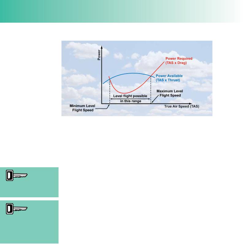
A graph of power available from the engine-propeller combination and power required for level fight, against true airspeed, can be established for any aircraft. A graph of this type, identical to the one you met in Chapter 3, is depicted at Figure 4.2.
421
Order: 6026
Customer: Oleg Ostapenko E-mail: ostapenko2002@yahoo.com
Customer: Oleg Ostapenko E-mail: ostapenko2002@yahoo.com
CHAPTER 4: EN-ROUTE PERFORMANCE
Both the lowest speed
for level flight and the
highest speed for level flight require full power.
Excess power available from
the enginepropeller
combination, over and above that required for level flight, can be used either to accelerate or climb the aircraft.
Figure 4.2 A graph of power required for level flight and power available from the propeller-engine combination, against true airspeed.
Any engine-propeller combination ftted to an aircraft can deliver a given maximum amount of thrust horsepower at given airspeeds. This information is given by the power available curve in Figure 4.2. Similarly, the total drag generated by the aircraft at the various speeds requires a given amount of thrust horsepower to overcome that drag in order for the aircraft to maintain straight and level fight. This information is given by the power required curve in Figure 4.2.
You will notice that the curves intersect each other in two places. An aircraft is able to maintain straight and level fight at speeds on the horizontal axis between the two intersections. In other words, wherever the power available curve is above the power required curve, level fight can be maintained. The speed corresponding to the intersection on the left is the slowest speed at which level fight is possible; the power required for level fight at that speed corresponds exactly to the power available from the engine-propeller combination. That power can only be delivered at full throttle. Consequently you can see that for an aircraft to fy level at the slowest possible speed, the pilot must open the throttle fully. If the aircraft is fown at a speed slower than the speed indicated, the aircraft will descend.
The right hand intersection of the two curves corresponds to the highest level fight speed attainable by the aircraft. Again the power required at that speed corresponds exactly to the power available and will require full throttle to deliver. If the pilot attempts to fy faster than this speed, the aircraft will descend.
Full power is required at the slowest speed for level fight because low speed requires high angles of attack which generate high levels of induced drag which must be balanced by the engine delivering all the power it has available. At the highest speed attainable, angle of attack is very small, but, as the speed is high, parasite drag is high which again requires full power.
At all speeds between the minimum and maximum level fight speeds, there is power available from the engine-propeller combination over and above the power required, and the aircraft is fying at less than full throttle. This excess power available can be used either to accelerate the aircraft in level fight or to climb the aircraft.
422