Добавил:
Опубликованный материал нарушает ваши авторские права? Сообщите нам.
Вуз: Предмет: Файл:

ppl_05_e2

.pdf
Скачиваний:
3789
Добавлен:
26.01.2018
Размер:
16.26 Mб
Скачать

ID: 3658

Customer: Oleg Ostapenko E-mail: ostapenko2002@yahoo.com Customer: Oleg Ostapenko E-mail: ostapenko2002@yahoo.com

CHAPTER 1

INTRODUCTION

353

Order: 6026

Customer: Oleg Ostapenko E-mail: ostapenko2002@yahoo.com

Customer: Oleg Ostapenko E-mail: ostapenko2002@yahoo.com

CHAPTER 1: INTRODUCTION

354

ID: 3658

Customer: Oleg Ostapenko E-mail: ostapenko2002@yahoo.com

Customer: Oleg Ostapenko E-mail: ostapenko2002@yahoo.com

CHAPTER 1: INTRODUCTION

INTRODUCTION.

Figure 1.1 Take-off.

The section on Mass and Balance in the Aeroplanes volume of this series of text books emphasised the need for a pilot to ensure that his aircraft was properly loaded, whether be it with passengers, baggage or fuel, so that both the centre of gravity and the all-up mass (or weight) remain within prescribed limits. With the centre of gravity position and all-up mass within limits, the pilot can be confdent that the aircraft will be controllable and not susceptible to overstress during fight.

This section on Aircraft Performance is devoted to explaining how the performance of a correctly-loaded aircraft must be adequate for the environment in which it will fy; that is to say, the dimensions of the airfeld and runways and the prevailing atmospheric and meteorological conditions. For instance, if the aircraft is loaded to its maximum authorised mass, and the centre of gravity is within limits, but the runway is not long enough for the aircraft to get airborne, then the aircraft’s load will have to be reduced.

The consequences for a pilot of failing to take into account the performance of his aircraft, and the physical and meteorological conditions prevailing at an aerodrome he intends to use, are potentially serious. His aircraft may fail to get airborne, fail to clear obstacles on the climb-out, or over-run the runway on landing.

There are very strict requirements for calculating the performance of public transport aircraft. However, these rules are not normally applicable to light aircraft operations. Nevertheless, the United Kingdom Civil Aviation Authority (UK CAA) strongly recommends that the safety factors which apply to public transport fights should be applied to general aviation fights too.

UK CAA Safety Sense Leafet No 7 contains valuable advice from the UK CAA on

Aeroplane Performance in respect of light aircraft.

Under JAR-FCL/EASA performance regulations, light, single-engined piston aircraft are classifed as Category B aircraft. (In the former UK-only Categorisation System, the Performance Group of this class of aircraft is E.) The performance fgures for

Category B aircraft provided by the manufacturer are known as gross performance fgures.

The CAA

strongly recommends

that public

transport safety factors should be applied to private flights.

355

Order: 6026

Customer: Oleg Ostapenko E-mail: ostapenko2002@yahoo.com

Customer: Oleg Ostapenko E-mail: ostapenko2002@yahoo.com

CHAPTER 1: INTRODUCTION

Performance

figures in light aircraft

manuals do not usually include any safety factors.

It is the

pilot’s legal obligation, in accordance

with Article 52 of the Air Navigation Order, to assure himself that his aircraft

can deliver the required performance to carry out safely any planned flight.

The most simple way to defne the expression “gross performance fgures” is to say that the fgures assume that an aircraft is new, and that it is fown from a hard runway by a professional test pilot, in ideal conditions. When these gross performance fgures are factored to allow for an in-service aircraft fown by an average pilot, the gross performance fgures are adjusted to give what are known as net performance fgures. Net performance fgures defne lower performance than gross performance fgures.

The CAA strongly recommends that net performance fgures should be applied to general aviation fights.

The CAA-approved performance charts for any given aircraft contain unfactored data. Consequently, the UK CAA recommends that a safety factor of 1.33 be applied to published take-off performance fgures obtained from performance documentation.

The CAA likewise recommends that a safety factor of 1.43 be applied to the manufacturer’s published landing fgures. (NB - The JAR-OPS Perf B take-off safety factor is 1.25).

This section on Aircraft Performance, then, examines how pilots should interpret the performance fgures for aircraft, published in an aircraft’s Flight Manual, or Pilot’s

Operating Handbook, and in other performance documentation. The performance documents applicable to any given aircraft are specifed in the aircraft’s Certifcate of Airworthiness.

As we have discussed, the performance fgures contained in the above documents are gross performance fgures. This section will teach you how to interpret those fgures in order to predict the performance of your aircraft in actual and expected fight conditions. You will learn, therefore, how to take the gross performance fgures for your aircraft and turn them into more realistic net performance fgures.

It is the pilot’s legal obligation, in accordance with Article 52 of the Air Navigation Order 2005, to assure himself that his aircraft can deliver the required performance to carry out safely any planned fight. The pilot, therefore, must always study carefully the performance data that apply to his aircraft and apply any mandatory limitation published by the CAA. He should also give serious consideration to applying any

CAA recommended safety factors to aircraft performance fgures.

Figure 1.2 Landing.

356

ID: 3658

Customer: Oleg Ostapenko E-mail: ostapenko2002@yahoo.com Customer: Oleg Ostapenko E-mail: ostapenko2002@yahoo.com

CHAPTER 2

TAKE-OFF

357

Order: 6026

Customer: Oleg Ostapenko E-mail: ostapenko2002@yahoo.com

Customer: Oleg Ostapenko E-mail: ostapenko2002@yahoo.com

CHAPTER 2: TAKE-OFF

358

ID: 3658

Customer: Oleg Ostapenko E-mail: ostapenko2002@yahoo.com

Customer: Oleg Ostapenko E-mail: ostapenko2002@yahoo.com

CHAPTER 2: TAKE-OFF

TAKE-OFF.

An aircraft’s take-off performance is dependent on several variables which include:

Aircraft mass (or weight).

Aerodrome pressure altitude.

Air temperature.

Air humidity.

Wind strength and direction.

Runway length and slope.

Nature of runway surface (including contaminants).

Flap settings.

Definition of “T ake-Off”.

The take-off stage of fight is defned as being from brakes-off until the aircraft reaches a defned screen height following lift-off. For light aircraft this screen height is 50 ft.

After lift-off, a specifc speed needs to be gained at the screen height. This is called the take-off safety speed which must be at least 20% greater than the stalling speed (VS). The take-off safety speed, then, must be greater than 1.2 VS.

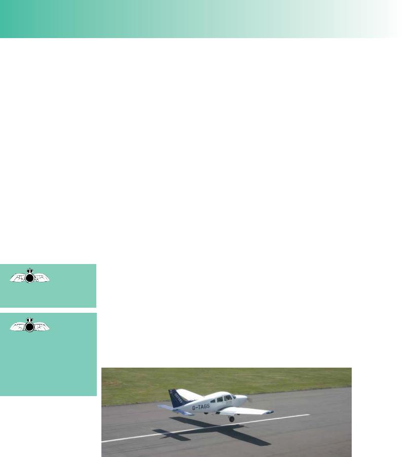
Figure 2.1 The take-off stage of flight for a light aircraft: from brakes-off until the aircraft reaches 50 feet.

Take-Off.

The take-off can be divided into the two parts. The frst is the take-off roll or takeoff run which is the distance travelled while the aircraft is still on the ground, in other words, from brakes-off to lift-off. When calculated for a particular aircraft on a particular day, this distance is called the Take-Off Run Required (TORR).

The second part of the take-off is the initial climb which is the distance covered from lift-off until the aircraft reaches the screen height of 50 feet. The combined length of the take-off run and initial climb is known as the take-off distance. When take-off distance is calculated for a particular aircraft on a particular day, take-off distance is called the Take-Off Distance Required.

Pilots need to make sure that the Take-Off Distance Required does not exceed

359

Order: 6026

Customer: Oleg Ostapenko E-mail: ostapenko2002@yahoo.com

Customer: Oleg Ostapenko E-mail: ostapenko2002@yahoo.com

CHAPTER 2: TAKE-OFF

the Take-Off Distance Available, at the airfeld in use. statement, but many incidents have occured which consideration is often forgotten.

This may seem an obvious suggest that this important

We will now examine the various distances relevant to the take-off.

Take-Off Run Available is

the length of runway

available for an aircraft’s ground run, threshold to threshold, excluding any stopway or clearway.

Figure 2.2 Take-Off Distance Required.

Take-Off Run.

Take-Off Run Available (TORA).

The take-off run available (TORA) is defned as being the length of runway which is declared available by the appropriate authority and suitable for the ground run of an aircraft taking off. Generally speaking, the TORA is the total length of the runway from threshold to threshold, excluding any stopway.

Figure 2.3 Take-Off Run Available - The length of runway suitable for the ground run of an aircraft on taking off.

Stopway.

Some runways have a stopway at either or both ends of the TORA. The stopway is an extension to the runway, able to support the weight of an aircraft, which is to be used to bring an aircraft to a stop in the event of an abandoned take off, and may not be used for any other purpose. The stopway is not included in the length of the

360

ID: 3658

Customer: Oleg Ostapenko E-mail: ostapenko2002@yahoo.com

Customer: Oleg Ostapenko E-mail: ostapenko2002@yahoo.com

CHAPTER 2: TAKE-OFF

TORA. The TORA plus any length of stopway is called the Accelerate Stop Distance Available or ASDA. The ASDA is sometimes also known as the Emergency Distance Available (EMDA or EDA).

The Stopway

is an extension to

the runway for emergency use only.

That part of

the take-off strip which

indicates

the Take-Off Run Available and the Stopway is called the Accelerate-Stop Distance Available or the Emergency Distance Available.

Figure 2.4 ASDA (Acceleration Stop Distance Available) = TORA + Stopway

Clearway.

The term clearway is defned as an area beyond the end of the runway, in the direction of take off, under the airport’s authority, which is clear of any signifcant obstacles and suitable for an aircraft to make its initial climb to the screen height (See Figure 2.5). Note that a clearway may include the stopway but need not be a surface in any way suitable to bear the weight of an aircraft; in fact, the clearway could be over water.

Take-Off Distance Available.

The TORA plus any clearway gives a distance known as the Take-Off Distance Available (TODA). If a runway possesses neither stopway nor clearway, TODA and ASDA are the same as TORA. For many small aerodromes, the TODA is declared to be the same distance as the TORA. Always check this fact in the Aerodrome Section (AD) of the AIP.

The Clearway

is an area beyond the

end of the

TORA under the airport’s authority, clear of obstacles.

The Take-

Off Distance Available

(TODA) is

defined as the TORA plus any clearway available.

Figure 2.5 The declared distances.

For any given runway, the TODA, ASDA and TORA, together with the Landing Distance Available (LDA) (See Chapter 4), are known as the declared distances.

361

Order: 6026

Customer: Oleg Ostapenko E-mail: ostapenko2002@yahoo.com

Customer: Oleg Ostapenko E-mail: ostapenko2002@yahoo.com

CHAPTER 2: TAKE-OFF

Take-Off Distance Required.

Based on the take-off performance of his aircraft, a pilot must be able to calculate the Take-Off Distance Required for the aircraft in prevailing meteorological conditions for a given runway state. Having calculated Take-Off Distance Required and applied the necessary correction factors and safety factors, the pilot must be able to see a healthy margin between the Take-Off Distance Required and the Take-Off Distance Available. Calculating Take-Off Distance Required is the subject of the rest of this chapter.

TAKE-OFF PERFORMANCE.

In considering the factors which infuence take-off performance, it will help you to recall two equations that you met in the Principles of Flight section of this book: the lift equation and the equation derived from Newton’s 2nd Law linking the thrust force developed by the engine-propeller combination (or jet engine) with the mass of the aircraft and the acceleration that the aircraft is capable of achieving. These equations are as follows:

Lift = C ½ ρv2S ....................

(1)


L


and


Thrust (T) = mass (m) × acceleration (a) ....................

(2)

The latter equation, following simple mathematical transposition, may be written as

a = T ....................

(3)

m


Furthermore, it is straightforward, using Newton’s equations of motion, to derive a third equation relating velocity, v, acceleration, a, and distance, S:

s = v2 ....................

(4)

2a


Figure 2.6 The Take-Off Distance formulae.

362

Соседние файлы в предмете [НЕСОРТИРОВАННОЕ]