

Lect5-Optical_fibers_2
.pdfPlot of the normalized propagation constant b as a function of V for various LP modes
b
2.405
V
V = (2πa/λ) (n12 – n22)1/2 = (u2 + w2)1/2
b = (β2 – k22)/(k12 – k22) |
(see p.41) |
21 |

Number of guided modes
The total number of guided modes M for a step-index fiber is approximately related to the V number (for V > 20) as follows,
M ≈ V2 / 2
e.g. A multimode step-index fiber with a core diameter of 80 µm and a relative index difference of 1.5 % is operating at a wavelength of
0.85 µm. If the core refractive index is 1.48, estimate (a) the normalized frequency for the fiber; (b) the number of guided modes.
(a)V = (2π/λ) a n1 (2 )1/2 = 75.8
(b)M ≈ V2 / 2 = 2873 (i.e. nearly 3000 guided modes!)
22

Cutoff wavelength
The cutoff wavelength for any mode is defined as the maximum wavelength at which that mode propagates. It is the value of λ that corresponds to Vc for the mode concerns. For each LP mode, the two parameters are related
λc(lm) = (2πa/(Vc(lm)) (n12 – n22)1/2
The range of wavelengths over which mode lm will propagate is thus 0 < λ < λc(lm).
For a fiber to operate single mode, the operating wavelength must be longer than the cutoff wavelength for the LP11 mode.
This is an important specification for a single-mode fiber, and is usually given the designation λc. We find λc by setting Vc = 2.405. The range of wavelengths for singlemode operation
is λ > λc. |
23 |
|

Singlemode condition
For single-mode operation, only the fundamental LP01 mode exists.
The cutoff normalized frequency (Vc) for the next higher order (LP11) mode in step-index fibers occurs at Vc = 2.405.
=> single-mode propagation of the LP01 mode in step-index fibers:
V < 2.405
e.g. Determine the cutoff wavelength for a step-index fiber to exhibit single-mode operation when the core refractive index is 1.46 and the core radius is 4.5 µm, with the relative index difference of 0.25 %.
λc = (2πan1/2.405) (2 )1/2 = 1214 nm.
Hence, the fiber is single-mode for λ > 1214 nm. |
24 |
|

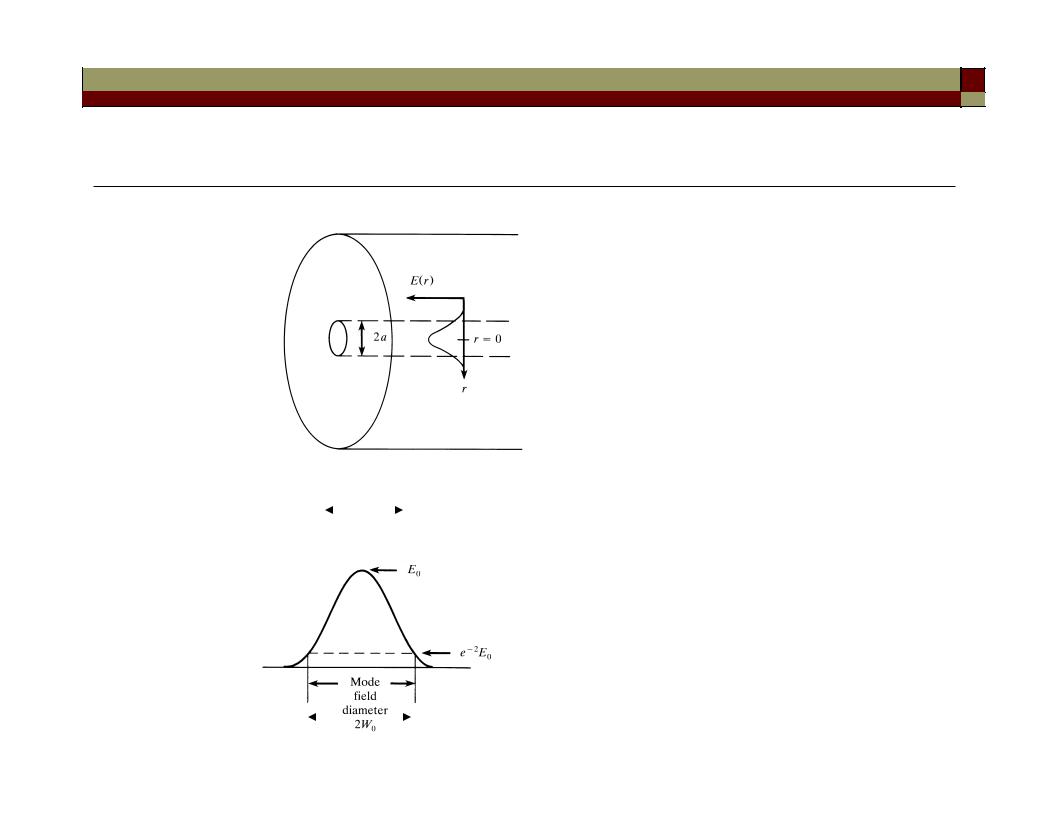
Gaussian approximation for the LP01 mode field
The LP01 mode intensity varies with radius as J02(ur/a) inside the core and as K02(wr/a) in the cladding. The resultant intensity profile turns out to closely fits a Gaussian function having a width w0, known as the mode-field radius.
This is defined as the radial distance from the core center to the 1/e2 point of the Gaussian intensity profile.
A similar Gaussian approximation can be applied to the fundamental symmetric slab waveguide mode.
|
E(r) = E(0) exp (-r2 / w02) |
=> |
I(r) = I(0) exp(-2r2/w02) |
Mode-field diameter (MFD) = 2w0 (rather than the core diameter) characterizes the functional properties of single-mode fibers.
(w0 is also called the spot size.) |
25 |
|
Mode-field diameter
ncore |
|
|
|
|
|
|
|
|
|
|
|
|
|
|
|
|
|
|
|
|
“Corning SMF-28” single-mode |
|
|
nclad |
|
|
|
|
|
|
|
|
|
||
|
|
|
|
|
|
|
|
fiber has MFD: |
|
||
|
|
|
core dia. |
|
9.2 m at 1310 nm |
|
|||||
|
|
|
|
|
|||||||
|
|
|
|
|
|
|
|
|
|
10.4 m at 1550 nm |
|
|
|
|
|
|
|
|
|
|
|||
|
|
|
|
|
|
|
|
|
|
core diameter: 8.2 m |
|
|
|
|
|
|
|
|
|
|
|
MFD > core diameter |
|
|
|
|
|
|
|
|
|
|
|||
|
|
|
|
|
|
|
|
|
|||
|
|
|
|
|
|
|
|
|
|
|
|
|
|
|
|
|
|
|
|
|
|
|
|
|
|
|
|
|
|
MFD |
26 |
||||
|
|
|
|
|
|
|
|
|
|||

Mode-field diameter vs. wavelength
11 µm
1550 nm
λc ~ 1270 nm |
λ = 1550 nm |
λ = 1320 nm |
core |
• Mode-field intensity distribution can be measured directly by near-field imaging the fiber output.
Why characterize the MFD for single-mode fibers?
27
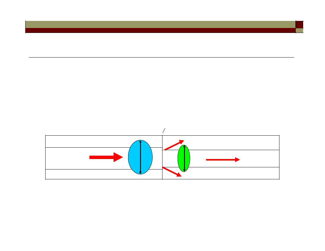
Mode-field diameter mismatch
Ans.: Mismatches in mode-field diameter can increase fiber splice loss.
e.g. Splicing loss due to MFD mismatch between two different SMF’s
~ dB loss per splice
m 10 |
m 8 |
|
SMF1 |
splicing |
SMF2 |
|
(A related question: why do manufacturers standardize the |
|
cladding diameter?) |
28 |
|
Remarks on single-mode fibers
• no cutoff for the fundamental mode
• there are in fact two normal modes with orthogonal polarizations
E E
29

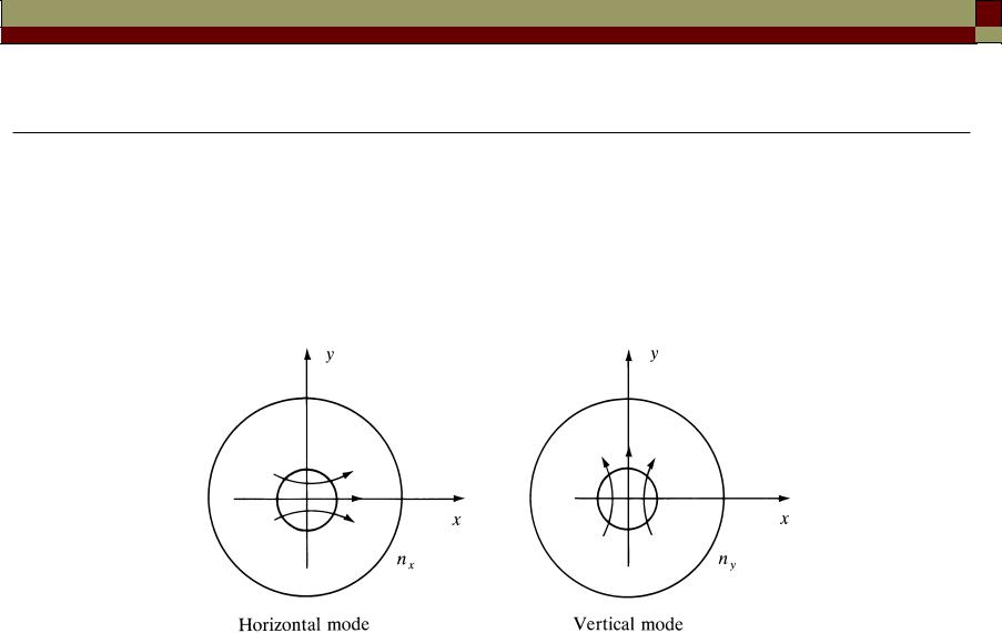
Fiber birefringence
In ideal fibers with perfect rotational symmetry, the two modes are degenerate with equal propagation constants (βx = βy), and any polarization state injected into the fiber will propagate unchanged.
In actual fibers there are imperfections, such as asymmetrical lateral stresses, non-circular cores and variations in refractive-index profiles. These imperfections break the circular symmetry of the ideal fiber and lift the degeneracy of the two modes.
The modes propagate with different phase velocities, and the difference between their effective refractive indices is called the fiber birefringence,
B = |ny – nx|
30