

Lect5-Optical_fibers_2
.pdfFiber bending loss and mode-coupling to higher-order modes
Phase velocity  cannot exceed c,
and thus radiation
“macrobending” |
“microbending” – power |
(how do we measure bending loss?) |
coupling to higher-order |
|
modes that are more lossy. |
71

Dispersion in fibers
72

Dispersion in fibers
Dispersion is the primary cause of limitation on the optical signal transmission bandwidth through an optical fiber.
Recall from Lecture 4 that there are waveguide and modal dispersions in an optical waveguide in addition to material dispersion.
Both material dispersion and waveguide dispersion are examples of chromatic dispersion because both are frequency dependent.
Waveguide dispersion is caused by frequency dependence of the propagation constant β of a specific mode due to the waveguiding effect. (recall the b vs. V plot of a specific mode)
The combined effect of material and waveguide dispersions for a particular mode alone is called intramode dispersion.
73

Modal dispersion
Modal dispersion is caused by the variation in propagation constant between different modes; it is also called intermode dispersion. (recall the b vs. V plot at a fixed V)
Modal dispersion appears only when more than one mode is excited in a multimode fiber. It exists even when chromatic dispersion disappears.
If only one mode is excited in a fiber, only intramode chromatic dispersion has to be considered even when the fiber is a multimode fiber.
74
Material dispersion
For optical fibers, the materials of interest are pure silica and doped silica.
The parameters of interest are the refractive index n, the group index ng and the group velocity dispersion D.
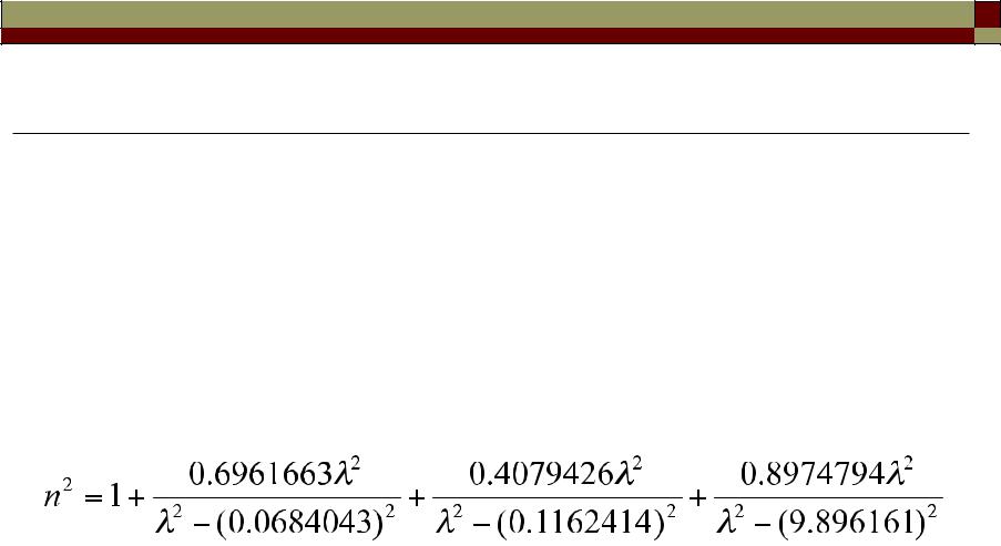
The index of refraction of pure silica in the wavelength range between 200 nm and 4 µm is given by the following empirically fitted Sellmeier equation:
where λ is in micrometers.
The index of refraction can be changed by adding dopants to silica, thus facilitating the means to control the index profile
of a fiber. Doping with germania (GeO2) or alumina
75
increases the index of refraction.
Fiber dispersion
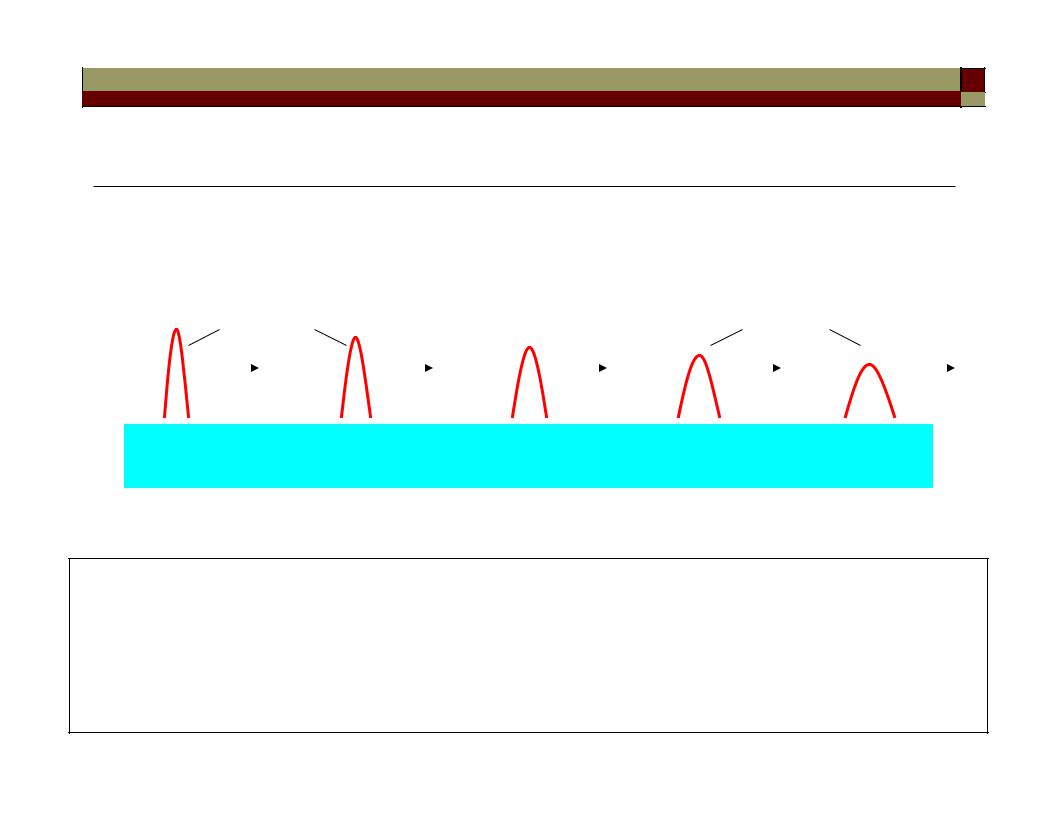
• Fiber dispersion results in optical pulse broadening and hence digital signal degradation.
Optical pulse |
|
|
|
broadened pulse |
|||||
|
|
|
|
|
|
|
|
|
|
Optical fiber
input |
output |
Dispersion mechanisms: 1. Modal (or intermodal) dispersion
2.Chromatic dispersion (CD)
3.Polarization mode dispersion (PMD)
76
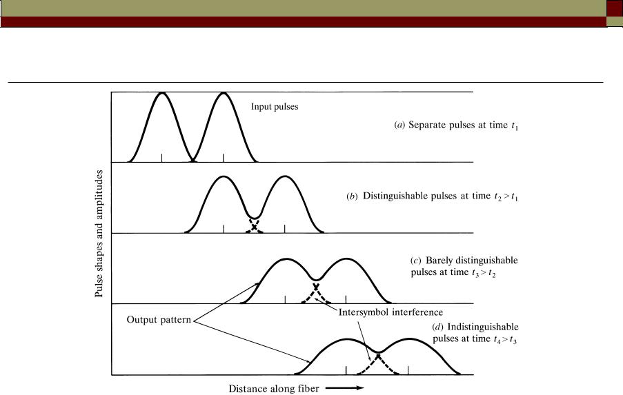
Pulse broadening limits fiber bandwidth (data rate)
1 0 1
1 0 1
Intersymbol interference (ISI) 
Signal distorted
Fiber length (km)
• An increasing number of errors may be encountered on the digital |
|
optical channel as the ISI becomes more pronounced. |
77 |
|

Modal dispersion
• When numerous waveguide modes are propagating, they all travel with different velocities with respect to the waveguide axis.
• An input waveform distorts during propagation because its energy
is distributed among several modes, each traveling at a different speed.
• Parts of the wave arrive at the output before other parts, spreading out the waveform. This is thus known as multimode (modal) dispersion.
• Multimode dispersion does not depend on the source linewidth (even a single wavelength can be simultaneously carried by multiple modes in a waveguide).
• Multimode dispersion would not occur if the waveguide allows only one mode to propagate - the advantage of single-mode waveguides! 78
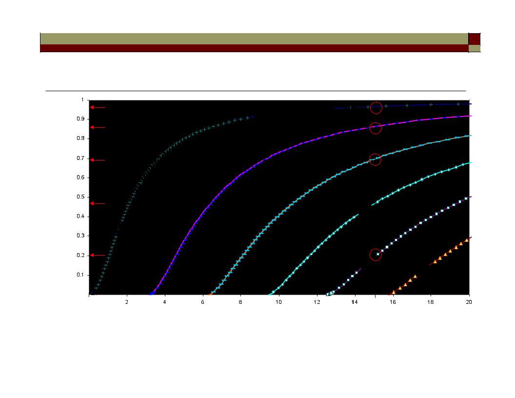
Modal dispersion as shown from the mode chart of a symmetric slab waveguide
(neff = n1)
Normalized guide index b
(neff = n2) 


m=0


1 |
TE |
2 |
|
3


 TM
TM

4


 5
5


V ( 1/λ)
• Phase velocity for mode m = ω/βm = ω/(neff(m) k0) |
|
(note that m = 0 mode is the slowest mode) |
79 |
|
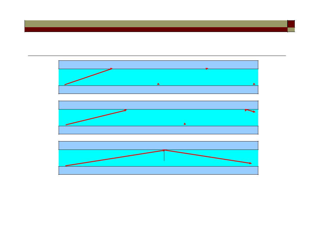
Modal dispersion in multimode waveguides
m=2 θ2
m=1 θ1

m=0 |
θ0 |
The carrier wave can propagate along all these different “zig-zag” ray paths of different path lengths.
80