

2841(ин.яз
.).pdfEYELASH CURLER
BACKGROUND OF THE INVENTION
1.Field of the Art
This invention relates to an eyelash curler, and more particularly to a scissor type eyelash curler which is arranged
to guarantee stabilized performances in eyelash curling operations, and which is capable of beautifully curling eyelashes free of distortions.
2.Prior Art
Generally, in order to shape eyelashes into a beautifully curled form, it is necessary for an eyelash curler to be able to provide stable performances in curling operations by an eyelash pressing member and an eyelash holder member which can be operated toward and away from each other in a properly faced state free of deviational movements in the direction of an eyelash gripping line between the eyelash pressing and holder members (in the direction of an eyelash gripping line extending longitudinally of the eyelash pressing and holder members). Deviational movements of the above-mentioned eyelash pressing and holder members in the direction of the eyelash gripping line could cause the eyelashes between them to roll over in deviational directions, making it difficult to set the eyelashes in a desired curled shape.
As a countermeasure for this problem, in the case of scissor type eyelash curlers which have been in wide use and which have a pair of scissor arms pivoted on a pivoting pin in the fashion of a pair of scissors, various attempts have been made to prevent deviational movements of eyelash pressing and holder members as caused by saccadic movements at the pivotally connected portions of the scissor arms, by providing guide members on the scissor arm on the part of the eyelash pressing member in such a manner as to guide the opposite ends of the eyelash holder for upward and downward movements during a curling operation, maintaining the eyelash holder member in a properly faced position relative to the eyelash pressing member free of positional deviations. However, it has been found that guide members of this sort have inherent drawbacks because they tend to obstruct the eyelash curling operations, barring to use the entire length of a gripping portion between the eyelash pressing and holder members effectively from one end to the other, resulting in inferior operational performance quality.
SUMMARY OF THE INVENTION
It is an object of the present invention to provide a scissor type eyelash curler as mentioned above, which can guarantee stabilized operational performances by an eyelash pressing member and an eyelash holder member which are movable toward and away from each other in a properly faced state, free of positional deviations in the direction of an eyelash gripping line to obviate the use of the conventional guide means for the eyelash holder member, thereby precluding the above-mentioned problem of the conventional guide means which easily come into the way of eyelash curling operations, and at the same time enabling the user to curl eyelashes into a distortion-free beautifully curled shape.
31
It is another object of the present invention to provide an eyelash curler which employs an extremely simple means for operating the eyelash holder member and pressing members toward and away from each other stably in a properly faced state and without deviations in the direction of an eyelash gripping line between the holder and pressing members.
As for means for operating the eyelash holder and pressing members in properly faced relations with each other as mentioned above, generally it is conceivable to step up the level of precision machining operations on mechanical parts taking part in the pivoting movements of the paired scissor arms, which are pivotally supported on a pivoting pin, to such a degree as to preclude the possibilities of saccadic movements of the respective scissor arms at their pivotally connected portions. However, such a solution means invariably leads not only to increases in manufacturing and machining costs of the scissor arms, but also to scissor arms which lack smoothness in opening and closing movements due to tight frictional contact of precision machined surfaces.
It is a further object of the present invention to provide a simple and inexpensive eyelash curler construction which makes it possible to operate the eyelash holder and pressing members toward and away from each other in a properly faced state and free of deviational movements in the direction of the eyelash gripping line, without necessitating to step up the level of precision machining operations on the component parts which are associated with pivoting movements of the paired scissor arms.
It is still a further object of the invention to provide an eyelash curler which is arranged to clamp eyelashes between an eyelash holder member and an eyelash pressing member through a resilient member of a synthetic resin material, which is provided on the eyelash holder member and adapted to be partially deviated in the direction of an eyelash gripping line under the influence of a clamping force applied by the pressing member, in such a way as to prevent twisting of eyelashes thereby permitting to curl same in an appropriate direction.
It is another object of the present invention to provide an eyelash curler which is arranged to guarantee safety of the eyeball and surrounding facial areas of the user even in the event of unexpected breakage of a component part or parts on which a relatively large force is applied at the time of a curling operation.
In accordance with the present invention, the above-stated objectives are achieved by the provision of a scissor type eyelash curler including a pair of scissor arms pivotally supported on a pivoting pin for opening and closing movements in the fashion of a pair of scissors, and an eyelash gripper including an eyelash holder member and an eyelash pressing member to be operated toward and away from each other and in face to face relation with each other by closing and opening movements of the scissor arms, characterized in that the eyelash curler essentially includes: an eyelash pressing member mounted on a fore end portion of one of the scissor arms; a link lever having a base end portion thereof pivotally supported on the one scissor arm through a support pin at a point intermediate between the eyelash pressing member and the pivoting pin of the paired scissor arms, and supporting an eyelash holder member securely on a fore end portion thereof in a face to face relation with the eyelash pressing member; an intermediate link member pivotally connected between a fore end portion of the link lever and a fore end portion of the other scissor arm; and a guide tongue provided on the one scissor arm at the connection and in association with the link lever to restrict saccadic
32
movements of the link lever in a direction perpendicular to a rotational plane about the axis of the support pin…
What is claimed is:
1. A scissor type eyelash curler including a pair of scissor arms pivotally supported on a pivoting pin for opening and closing movements in the fashion of a pair of scissors, and an eyelash gripper including an eyelash holder member and an eyelash pressing member provided in a face to face relation with each other and operated toward and away from each other by closing and opening movements of said scissor arms, characterized in that said eyelash curler essentially comprises:
said eyelash pressing member mounted on a fore end portion of one scissor arm for pressing eyelashes;
a link lever having a base end portion thereof pivotally supported on said one scissor arm through a support pin at a point intermediate between said eyelash pressing member and said pivoting pin of said paired scissor arms, and fixedly supporting said eyelash holder member on a fore end portion thereof in a face to face relation with said eyelash pressing member;
an intermediate link member pivotally connected between a fore end portion of said link lever and a fore end portion of the other scissor arm; and
a guide tongue integrally provided on said one scissor arm at the connection with and in association with said link lever to restrict saccadic movements of said link lever in a direction perpendicular to a rotational plane about the axis of said support pin.
2.An eyelash curler as defined in claim 1, wherein said link lever is constituted by a pair of lever plates, which lever plates being pivotally supported on said one scissor arm through said support pin at the respective base end portions located to embrace opposite sides of said one scissor arm, and said guide tongue is held in intimate contact with inner surfaces of said lever plates to restrict saccadic movements of said link lever.
3.An eyelash curler as defined in claim 1, wherein said eyelash holder member is constituted by a nesting piece of a channel-like shape securely mounted on a fore end portion of said link lever, and a resilient member of synthetic resin material securely fitted in said nesting piece.
4.An eyelash curler as defined in claim 3, wherein said resilient member is formed in a hollow tubular shape internally provided with an axial hole substantially at a center position thereof for absorption of deformations of said resilient member at the time of an eyelash clamping operation.
5.An eyelash curler as defined in one of claims 1 to 3, wherein said intermediate link is connected to a fore end portion of said link lever at a position on the inner side of a protective wall securely fixed to the fore distal end of said link lever.
33

Задание 3. Прочитайте патент на криптографический ротор. 1) При необходимости соберите внешние данные о тексте (в качестве примера приведена статья из «Википедии»). 2) Найдите языковые средства, характерные для научно-технического стиля, объясните их назначение и подберите русские соответствия. 3) Выпишите синтаксические конструкции, характерные для данного типа документа. 4) Предложите свой вариант реферативного перевода текста.
A cryptographic rotor
Inventor: Leo Rosen
U.S. Classification 35/4
International Classification G09C 500
Claims
What is claimed is:
1.A cryptographic rotor including a first disc having an annular array of input contacts on one face thereof, a second disc having an annular array of output contacts on one face thereof, a plurality of wires connecting the input contacts to the output contacts in pairs, and means for supporting said two discs for rotative movement relative to each other.
2.A cryptographic rotor including a first disc having an annular array of input contacts thereon, a second disc having an annular array of output contacts thereon, and a support including means for mounting said discs thereon for rotative movement relative to each other and to said support, a plurality of wires connecting the said input contacts to the output contacts in pairs, and plugboard means for variably making the connections.
Drawings
This invention is in the cryptographic art and particularly is an improvement on commutating devices commonly used in electrical cryptographic apparatus.
34
One object of the present invention is to provide a cryptographic rotor with readily variable connections between the contacts thereof.
Another object is to provide readily variable paths through cryptographic rotors.
Other objects will be apparent from a reading of the following specification and claims. In the drawings:
FIG. 1 illustrates in diagram a cryptographic rotor of standard construction.
FIG. 2 is a view of the device of this invention, partly in section, and with one rotor element removed.
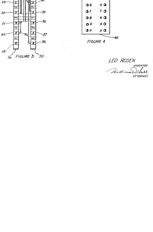
FIG. 3 is a somewhat diagrammatic edge view of the structure of this invention. FIG. 4 is a top view of the plugboard utilized in the invention.
35
Referring to the drawings, and particularly to FIG. 1, the conventional cryptographic rotor, which is substantially like that shown in U.S. Pat. No. 1,683,072, to Hebern, may be seen to comprise a body member 10, of Bakelite or some similar insulating material, a plurality of input contacts 11, and a similar plurality of output contacts 12. The input contacts are randomly connected to the output contacts so that an electrical signal introduced at a given input contact will not normally be carried to the corresponding output contact, but, instead, to an output contact displaced one or more positions from the input contact.
A rotor of the type described normally has fixed internal wiring, or wiring that can be changed only through considerable labor. Connections commonly are soldered.
With reference now to FIG. 2, the present invention may be seen to include a central member 15. Associated with central member 15, for limited rotation relative thereto, is a rotor element 16 including a rotor proper and a series of contacts 17 to 26, inclusive. Similarly mounted on the opposite side of central member 15 is another rotor element 30 (see FIG. 3) substantially like the element just described, and comprising a Bakelite element 35 and ten contacts. Only six of these last mentioned contacts, 36-41, and six contacts (19 through 24) of member 16, appear in FIG. 3. Attached to the upper portion of member 15 is a plugboard comprising a member 40 of insulating material and a number of sockets, as 41, adapted to receive cooperating plugs in both top and bottom.
Whereas, in the standard rotor, illustrated in FIG. 1, the input and the output contacts are connected directly, it will be seen in FIGS. 2 and 3, that, according to this invention, connecting wires, as 50, are each secured at one end to a different one of the several contacts of rotor elements 16 and 30, and provided at their other ends with plugs, as 42, adapted for insertion into the plugboard 40. Normally, of course, every one of the contacts will have secured to it a connecting wire 50. Only a few of the wires, however, are shown in the drawings.
It will, thus, be understood that the rotor of the present invention is not adapted to turn freely as a unit through a full 360° circle; the effects of such rotation, however, can be obtained as a result of the fact that each of the rotor elements 16 and 30 is movable a limited angular distance (fixed by the lengths of the wires 50) and that the two said elements move relative not only to support 15 but also to each other. Jumper cords, as 60, are provided, and these also are fitted with plugs, as 62, for insertion in the top of the plugboard 40. Each of the input contacts has associated with it a numerical character or other indicating device, as 70. For convenience, the sockets on the plugboard are arranged in two groups, each relating to one of the rotor elements 16 and 30, and these sockets likewise bear indicating devices, as the numerals 71.
The operation of the device should be apparent and will only be briefly described. Assuming that each contact has wire soldered or otherwise attached to it in the interior of the rotor, and that each wire is provided with a plug, and is long enough to permit rotation of the rotor elements proper, the plugs are inserted from below in plugboard 40 in any desired order. For the purposes of explanation, it can be assumed that "0" wire of rotor element 16 is plugged into the "0" socket of plugboard 40, on the left side thereof, " 1" wire into socket" 1", etc. The contact wires for rotor element 30 are similarly inserted in the right side of the plugboard. The jumper cords are then used to connect the input contacts to the output contacts through the plugboard Q in any desired order.
One set of contacts, for instance, 17 through 26 will normally serve as inputs to the rotor, and the other set will serve as outputs. As will be seen, the electrical paths through the rotor, in other words, the connections between input and output contacts, can readily be changed merely by changing the jumper cords. The paths can also be changed, of course, by altering connections between contacts and plugboard. Still further alterations can be made in the circuits through the rotor, when the device is used with one or more other rotors, by stepping one or
36
both of the elements 16 and 30 in either direction. Notches 75 are utilized for manual or mechanical stepping.
The above description is in specific terms and it should be understood that the invention is not limited to the exact structure shown and described. Rather, for the true scope of the invention reference should be had to the appended claims.
I claim:
1.A cryptographic rotor including a first disc having an annular array of input contacts on
one face thereof, a second disc having an annular array of output contacts on one face thereof, a plurality of wires connecting the input contacts to the output contacts in pairs, and means for supporting said two discs for rotative movement relative to
each other. |
|
|
|
|
|
|
|
|
2. |
A |
cryptographic |
rotor |
including |
a |
first |
disc |
having |
an annular array of input contacts thereon, a second disc having an annular array of output contacts thereon, and a support including means for mounting said discs thereon for rotative movement relative to each other and to said support, a plurality of wires connecting the said input contacts to the output contacts in pairs, and plugboard means for variably making the connections.
Фрагмент статьи про шифрмашину «Энигма» с сайта «Википедии».
«Как и другие роторные машины, Энигма состояла из комбинации механических и электрических систем. Механическая часть включала в себя клавиатуру, набор вращающихся дисков (роторов), которые были расположены вдоль вала и прилегали к нему, и ступенчатого механизма, двигающего один или более роторов при каждом нажатии клавиши. Конкретный механизм работы мог быть разным, но общий принцип был таков: при каждом нажатии клавиши самый правый ротор сдвигается на одну позицию, а при определённых условиях сдвигаются и другие роторы. Движение роторов приводит к различным криптографическим преобразованиям при каждом следующем нажатии клавиши на клавиатуре.
Механические части двигались, образуя меняющийся электрический контур, то есть, фактически, шифрование букв осуществлялось электрически. При нажатии клавиш контур замыкался, ток проходил через различные компоненты и в итоге включал одну из множества лампочек, отображавшую выводимую букву. Например, при шифровке сообщения, начинающегося с ASF..., оператор вначале нажимал кнопку A, и загоралась лампочка D, то есть D становилась первой буквой криптограммы. Оператор продолжал шифрование S таким же образом, и так далее.
Для объяснения принципа работы Энигмы приведен рисунок. Он упрощен, - на самом деле механизм состоял из 26 лампочек, клавиш, разъемов и электрических схем внутри роторов. Ток шел из батареи (1) через переключатель (2) в коммутационную панель (3). Коммутационная панель позволяла перекоммутировать соединения между клавиатурой
(2) и неподвижным входным колесом (4). Далее ток проходил через разъем (3), в данном примере неиспользуемый, входное колесо (4) и схему соединений трёх роторов (5) и входил в рефлектор (6). Рефлектор возвращал ток обратно, через роторы и входное колесо, но уже по другому пути, далее через разъем S, соединённый с разъемом D, через другой переключатель (9), и зажигалась лампочка. Таким образом, постоянное изменение электрической цепи, через которую шел ток, вследствие вращения роторов позволяло реализовать многоалфавитный шифр подстановки, что давало высокую устойчивость шифра для того времени.»
37

Задание 4. Прочитайте образец контракта и его перевода. Выпишите клишированные выражения и их перевод.
CONTRACTNo____
РТА "Nika", Nizhny Novgorod, Russian Federation, hereinafter referred to as the Seller, on the one part, and ____________ ,
hereinafter referred to as the Buyer, on the other part, have concluded the present Contract to the following effect:
1.SUBJECT MATTER OF THE CONTRACT
1.1.The Seller has sold and the Buyer has bought f.o.b. Odessa (Incoterms ICC 1990) __________in the amount of about 12 (twelve) tons as per Specifications (Appendix No 1). The above Specifications form an integral part of the present Contract.
2.PRICE AND TOTAL AMOUNT
2.1.Price per ton ____ US dollars. Prices to be firm for the whole period of the Contract.
2.2.Total amount of the Contract — approximately _____ US dollars.
КОНТРАКТ №_____
ПТА «Ника», г. Нижний Новгород, Российская Федерация, именуемая в дальнейшем «Продавец», с одной стороны, и , именуемый в дальнейшем «По-купатель», с другой стороны, заключили настоящий Контракт о нижеследующем:
1.ПРЕДМЕТ КОНТРАКТА
1.1. Продавец продал и Поку-патель купил на условиях фоб г. Одесса (Инкотермс МТП 1990) ______ в количестве около 12 (двенадцати) тонн согласно Специ-фикации (Приложение № 1), являющейся неотъемлемой частью настоящего Контракта.
2. ЦЕНА И ОБЩАЯ СТОИМОСТЬ
2.1.Стоимость одной тонны
____долларов США. Цены остаются неизменными на весь период действия Контракта.
2.2.Общаястоимость Контракта — около_____долларов США.
38
3. TERMS OF PAYMENT
3.1. Payment for the goods delivered under the present Contract shall be made by the Buyer in US dollars against the following set of documents in the Buyer's bank for collection
_____________________________
_____________________________
a) Bill of Lading — 1 original and 1 copy;
3. УСЛОВИЯ ПЛАТЕЖА 3.1. Платеж за товар, постав-ляемый
по настоящему Контракту, производится Покупателем в долларах США против следующих документов на инкассо в банке Покупателя: __________________
_____________________________
а) бортовой коносамент — 1 оригинал и 1 копия;
b)the Seller's Invoice — 1 original б) счет Продавца — 1 оригинал и 1
and 1 copy; |
копия; |
c)the Seller's Certificate of Quality в) сертификат качества Продавца — 1
— 1 original and 1copy.
4.DATES OF DELIVERY
4.1.The goods as per Appendix No 1 shall be delivered within
50days after the date of signing the Contract. Date of delivery is understood as date of Bill of Lading.
5.LIABILITIES
5.1. In the event of delay in delivery when the Seller fails tо meet the date stated in the Contract the Seller is to pay to the Buyer the penalty according to a convention provided there is no infringement of other rights of the Buyer concerning the delay in delivery. This penalty according to а convention is at the rate of 0,5 % for every calendar week of the delay within the first 4 weeks and 1 % for every subsequent calendar week of the total Contract value but not more than 10 %.
6. PACKING, MARKING, SHIPMENT
6.1.Sacks of 25 kg in a 20-feet container.
6.2.Packing of the goods shipped should provide proper conditions for the goods while shipment, loading and unloading.
6.3.Immediately after shipment of the goods the Seller should send by telex or fax the following information to the address of the Buyer:
оригинал и 1 копия. 4. СРОКИ ПОСТАВКИ
4.1. Товары, согласно Прило-жению № 1, должны быть поставлены в течение 50 суток со
дня подписания Контракта. Датой поставки считается дата бортового коносамента.
5. ОТВЕТСТВЕННОСТЬ СТОРОН 5.1. В случае задержки поставки товара в сравнении со сроком, указанным в Контракте, Продавец выплачивает Покупателю конвенциональный штраф, если при этом исключены нарушения других прав Покупателя, связанных с задержкой поставки. Этот конвенциональный штраф составляет 0,5 % за каждую календарную неделю задержки – в первые 4 недели и 1 % за каждую следующую неделю задержки от общей стоимости контракта, но не более 10 %.
6. УПАКОВКА, МАРКИРОВКА, ОТГРУЗКА
6.1.Мешки no 25 кг в 20-футовом контейнере.
6.2.Упаковка отгружаемых товаров должна обеспечивать сохранность товаров при транспортировке и при погрузочно-разгрузочных работах.
6.3.Немедленно после отгрузки товара Продавец обязан сообщить телексом или факсом в адрес Покупателя следующую информа-
39
—number of the Contract;
—number of Вill of Lading and Container;
—total number of consignments; —gross weight;
—net weight.
6.4. Shipment shall be made to the address:_____________
7. QUALITY
7.1. The quality of the goods is to be in strict conformity with the technical data of the manufacturing plant and must be confirmed by the Certificate
of Quality issued by the plant or by the Seller's Letter of Guarantee.
8. ACCEPTANCE
8.1. The goods are to be considered as delivered by the Seller and accepted by the Buyer: according to quality stated in Certificate of Quality of the manufacturing plant or in the Seller's Letter of Guarantee and according to quantity stated in the waybill.
9. GUARANTEE
9.1. Should any shortage be found in the goods delivered or should the quality of the goods be found not to correspond to the technical conditions of the Contract the Buyer shall have the right to submit a claim to the Seller within 30 days from the date of receipt of the goods in the port of destination. In this case the Buyer shall send to the Seller the documents substantiating the claim compiled with the participation of a representa-
tive of a neutral, competent organization. Should the claim prove to be justified, the Seller shall compensate for shortage or faulty goods within the least possible time to be fixed between the Parties. Ways of
compensation, such as recovery of short shipped quantity, replacement of faulty goods free of charge or reimbursement of their value, shall be determined by negotiations between the Parties.
цию:
—номер Контракта;
—номер бортового коносамента и контейнера;
—общее количество мест;
—вес брутто;
—вес нетто
6.4. Отгрузка производится в адрес:
_____________
7.КАЧЕСТВО
7.1. Качество товара должно отвечать техническим нормам заводаизготовителя и под-тверждаться сертификатом качества завода-изготовителя или
гарантийным письмом Продавца.
8.ПРИЕМКА
8.1. Товар считается переданным Продавцом и принятым Покупателем: по качеству, согласно сертификату качества заводаизготовителя или гарантийному письму Продавца, и в количестве согласно накладной.
9. ГАРАНТИИ 9.1. В случае обнаружения недовеса в
поставленных товарах или несоответствия качества товаров
техническим условиям Контракта, в течение 30 дней с даты получения товара в порту назначения Покупатель имеет право предъявить претензию Продавцу. В этом случае Покупатель
направляет Продавцу документы, подтверждающие претензию, которые составлены при участии представителя нейтральной компетентной организации. Если претензия окажется обоснованной, Продавец компенсирует недопоставленные либo некачественные товары в течение кратчайшего срока, ycтановленного сторонами. Способы компенсации, такие как возмещение недостающего коли-чества, замена некачественных товаров бесплатно или возмещение их стоимoсти,
40