

бакМИТ_КП2015 / Компоненты по вариантам / Операционные_усилители / MAX9622AXK
.pdf
|
EVALUATION KIT AVAILABLE |
|
|
MAX9622 |
Precision, High-Bandwidth Op Amp |
General Description
The MAX9622 op amp features rail-to-rail output and 50MHz GBW at just 1mA supply current. At power-up, this device autocalibrates its input offset voltage to less than 100µV. It operates from a single-supply voltage of 2.0V to 5.25V.
The MAX9622 is available in a tiny 2mm x 2mm, 5-pin SC70 package and is rated over the -40°C to +125°C automotive temperature range.
Applications
●● Power Modules
●● ADC Drivers for Industrial Systems ●● Instrumentation
●● Filters
Features
●● 50MHz UGBW
●● |
Low Input Voltage Offset Voltage (100μV max) |
|
||
●● |
Input Common-Mode Voltage Range Extends Below |
|||
|
Ground |
|
|
|
●● |
Wide 2.0V to 5.25V Supply Range |
|
||
●● |
Low 1mA Supply Current |
|
|
|
Ordering Information |
|
|
||
|
|
|
|
|
|
PART |
TEMP RANGE |
PIN- |
TOP |
|
PACKAGE |
MARK |
||
|
|
|
||
|
|
|
|
|
MAX9622AXK+T |
-40°C to +125°C |
5 SC70 |
AUA |
|
|
|
|
|
|
+Denotes a lead(Pb)-free/RoHS-compliant package. T = Tape and reel.
Typical Application Circuit
INPUT |
5.5kI |
5.5kΩ |
|
4.7nF |
14.3kΩ |
|
|
47pF |
|
|
VCC |
|
20kΩ |
OUTPUT |
|
|
|
|
|
VCC/2 |
20kΩ 
MAX9622
USING THE MAX9622 AS A LOWPASS BESSEL FILTER (CORNER FREQUENCY = 100kHz).
19-5227; Rev 1; 4/15
MAX9622 |
Precision, High-Bandwidth Op Amp |
Absolute Maximum Ratings
Supply Voltage (VCC to GND) |
.............................. |
-0.3V to +5.5V |
All Other Pins................................ |
(GND - 0.3V) to (V CC + 0.3V) |
|
Short-Circuit Duration to GND or VCC..................................... |
1s |
|
Continuous Input Current (any .................................pins) |
±20mA |
|
Thermal Limits (Note 1) |
|
|
Continuous Power Dissipation (TA = +70°C) |
245.4mW |
|
5-Pin SC70 (derate 3.1mW/°C ..........above +70°C) |
||
Operating Temperature Range......................... |
-40°C to +125°C |
Junction Temperature....................................................... |
+150°C |
Storage Temperature Range............................. |
-65°C to +150°C |
Lead Temperature (soldering, 10s).................................. |
+300°C |
Soldering Temperature (reflow)........................................ |
+260°C |
Note 1: Package thermal resistances were obtained using the method described in JEDEC specification JESD51-7, using a four-layer board. For detailed information on package thermal considerations, refer to www.maximintegrated.com/thermal-tutorial.
Stresses beyond those listed under “Absolute Maximum Ratings” may cause permanent damage to the device. These are stress ratings only, and functional operation of the device at these or any other conditions beyond those indicated in the operational sections of the specifications is not implied. Exposure to absolute maximum rating conditions for extended periods may affect device reliability.
Electrical Characteristics
(VCC = 5V, VIN+ = VIN- = 0V, RL = 10kΩ to VCC/2, TA = -40°C to +125°C, unless otherwise noted. Typical values are at TA = +25°C.) (Note 2)
PARAMETER |
SYMBOL |
CONDITIONS |
MIN |
TYP |
MAX |
UNITS |
|
POWER SUPPLY |
|
|
|
|
|
|
|
Supply Voltage Range |
VCC |
Guaranteed by PSRR |
|
2 |
|
5.25 |
V |
Supply Current |
ICC |
No load |
TA = +25°C |
|
1 |
1.5 |
mA |
-40°C ≤ TA ≤ +125°C |
|
|
2.1 |
||||
|
|
|
|
|
|
||
Power-Supply Rejection Ratio |
PSRR |
TA = +25°C |
|
97 |
126 |
|
dB |
-40°C ≤ TA ≤ +125°C |
|
93 |
|
|
|||
Power-Up Time |
tON |
|
|
|
3 |
|
ms |
DC SPECIFICATIONS |
|
|
|
|
|
|
|
Input Offset Voltage |
VOS |
After power-up autocalibration |
|
8 |
100 |
µV |
|
-40°C ≤ TA ≤ +125°C |
|
|
8 |
3000 |
|||
|
|
|
|
|
|||
Input Offset Voltage Drift |
ΔVOS |
|
|
|
3 |
|
µV/°C |
Input Bias Current |
IB |
TA = +25°C |
|
|
62 |
150 |
nA |
-40°C ≤ TA ≤ +125°C |
|
|
|
320 |
|||
|
|
|
|
|
|
||
Input Offset Current |
IOS |
TA = +25°C |
|
|
3 |
12 |
nA |
-40°C ≤ TA ≤ +125°C |
|
|
|
30 |
|||
|
|
|
|
|
|
||
Input Common-Mode Range |
VCM |
Guaranteed by CMRR, TA = -40°C to +125°C |
-0.1 |
|
VCC -1.3 |
V |
|
Common-Mode Rejection Ratio |
CMRR |
TA = +25°C |
|
87 |
121 |
|
dB |
-40°C ≤ TA ≤ +125°C |
|
80 |
|
|
|||
|
|
400mV ≤ VOUT ≤ |
TA = +25°C |
91 |
103 |
|
|
Large-Signal Gain |
AVOL |
VCC - 400mV |
-40°C ≤ TA ≤ +125°C |
84 |
|
|
dB |
400mV ≤ VOUT ≤ |
TA = +25°C |
77 |
89 |
|
|||
|
|
VCC - 400mV, RL = |
|
|
|
|
|
|
|
-40°C ≤ TA ≤ +125°C |
69 |
|
|
|
|
|
|
1kΩ to VCC/2 |
|
|
|
||
|
VOH - VCC |
RL = 10kΩ to VCC/2 |
|
|
|
60 |
|
Output Voltage Swing |
|
RL = 10kΩ to VCC/2 |
|
|
|
60 |
mV |
VOL |
RL = 10kΩ to GND, TA = +25°C |
|
|
40 |
|||
|
|
|
|
||||
|
|
RL = 10kΩ to GND |
|
|
|
48 |
|
Short-Circuit Current |
ISC |
(Note 3) |
|
|
80 |
|
mA |
www.maximintegrated.com |
Maxim Integrated │ 2 |
MAX9622 |
Precision, High-Bandwidth Op Amp |
Electrical Characteristics (continued)
(VCC = 5V, VIN+ = VIN- = 0V, RL = 10kΩ to VCC/2, TA = -40°C to +125°C, unless otherwise noted. Typical values are at TA = +25°C.) (Note 2)
PARAMETER |
SYMBOL |
|
|
CONDITIONS |
MIN |
TYP |
MAX |
UNITS |
|||
AC SPECIFICATIONS |
|
|
|
|
|
|
|
|
|
|
|
Gain-Bandwidth Product |
GBW |
|
|
|
|
|
|
|
50 |
|
MHz |
|
|
|
|
|
|
|
|
|
|
|
|
Large-Signal Bandwidth |
BWLS |
VOUT = 2VP-P |
|
|
|
|
|
3 |
|
MHz |
|
Slew Rate |
SR |
VOUT = 2VP-P, 10% to 90% |
|
20 |
|
V/µs |
|||||
Settling Time |
t |
To 0.1%, V |
OUT |
= 2V |
P-P |
, C |
= 10pF |
|
200 |
|
ns |
|
S |
|
|
|
L |
|
|
|
|
||
Total Harmonic Distortion |
THD |
f = 10kHz, VOUT = 2VP-P |
|
|
90 |
|
dB |
||||
Input Voltage-Noise Density |
eN |
f = 10kHz |
|
|
|
|
|
|
13 |
|
nV/√HZ |
Input Current-Noise Density |
iN |
f = 10kHz |
|
|
|
|
|
|
3 |
|
pA/√HZ |
Note 2: The device is 100% production tested at TA = +25°C. Temperature limits are guaranteed by design. Note 3: Guaranteed by design.
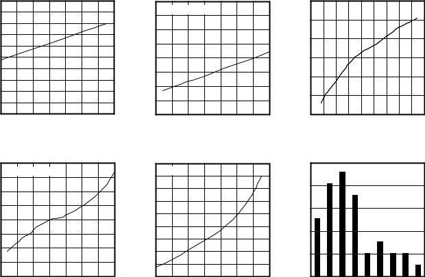
Typical Operating Characteristics
(VCC = 5V, RL = 10kΩ to VCC/2, TA = +25°C, unless otherwise noted.)
SUPPLY CURRENT vs. SUPPLY VOLTAGE |
QUIESCENT CURRENT vs. TEMPERATURE |
INPUT OFFSET VOLTAGE |
vs. COMMON-MODE VOLTAGE |
|
1.00 |
|
|
|
|
|
|
toc01 |
|
2.0 |
|
0.98 |
|
|
|
|
|
|
|
|
|
|
|
|
|
|
|
|
MAX9622 |
|
1.8 |
|
|
0.96 |
|
|
|
|
|
|
QUIESCENT CURRENT (mA) |
||
SUPPLY CURRENT (mA) |
|
|
|
|
|
|
1.6 |
|||
0.94 |
|
|
|
|
|
|
||||
|
|
|
|
|
|
|
||||
0.92 |
|
|
|
|
|
|
1.4 |
|||
0.90 |
|
|
|
|
|
|
1.2 |
|||
0.88 |
|
|
|
|
|
|
1.0 |
|||
0.86 |
|
|
|
|
|
|
||||
|
|
|
|
|
|
0.8 |
||||
0.84 |
|
|
|
|
|
|
||||
|
|
|
|
|
|
|
|
|
|
|
|
0.82 |
|
|
|
|
|
|
|
|
0.6 |
|
0.80 |
2.5 |
3.0 |
3.5 |
4.0 |
4.5 |
5.0 |
5.5 |
|
0.4 |
|
2.0 |
|
|
|||||||
|
|
|
SUPPLY VOLTAGE (V) |
|
|
|
|
|||
|
RLOAD = NO LOAD |
|
|
|
toc02 |
|
30 |
||
|
|
|
|
|
|
||||
|
|
|
|
MAX9622 |
|
|
|||
|
|
|
|
|
|
|
(µV) |
25 |
|
|
|
|
|
|
|
|
|
||
|
|
|
|
|
|
|
|
VOLTAGE |
20 |
|
|
|
|
|
|
|
|
15 |
|
|
|
|
|
|
|
|
|
OFFSET |
|
|
|
|
|
|
|
|
|
10 |
|
|
|
|
|
|
|
|
|
INPUT |
|
|
|
|
|
|
|
|
|
5 |
|
|
|
|
|
|
|
|
|
|
|
-50 |
-25 |
0 |
25 |
50 |
75 |
100 |
125 |
|
0 |
|
|
||||||||
|
|
TEMPERATURE (°C) |
|
|
|
|
|||
|
|
|
|
|
|
|
|
|
MAX9622 toc03 |
-0.5 |
0 |
0.5 |
1.0 |
1.5 |
2.0 |
2.5 |
3.0 |
3.5 |
4.0 |
|
|
COMMON-MODE VOLTAGE (V) |
|
|
|||||
OFFSET VOLTAGE vs. TEMPERATURE |
INPUT OFFSET VOLTAGE |
vs. SUPPLY VOLTAGE |
|
200 |
RLOAD = NO LOAD |
|
|
|
toc04 |
|
15 |
VCM = 0V |
|
|
|
|
|
toc05 |
||
|
|
|
|
|
|
|
|
|
|
|
|
||||||
|
150 |
|
|
|
MAX9622 |
|
10 |
|
|
|
|
|
MAX9622 |
||||
|
|
|
|
|
|
|
INPUT OFFSET VOLTAGE (µV) |
|
|
|
|
|
|
||||
OFFSET VOLTAGE (µV) |
100 |
|
|
|
|
|
|
5 |
|
|
|
|
|
|
|||
|
|
|
|
|
|
|
|
|
|
|
|
|
|||||
50 |
|
|
|
|
|
|
0 |
|
|
|
|
|
|
||||
|
|
|
|
|
|
-5 |
|
|
|
|
|
|
|||||
0 |
|
|
|
|
|
|
|
|
|
|
|
|
|||||
|
|
|
|
|
|
-10 |
|
|
|
|
|
|
|||||
-50 |
|
|
|
|
|
|
|
|
|
|
|
|
|||||
|
|
|
|
|
|
-15 |
|
|
|
|
|
|
|||||
|
|
|
|
|
|
|
|
|
|
|
|
|
|||||
-100 |
|
|
|
|
|
|
-20 |
|
|
|
|
|
|
||||
|
-150 |
|
|
|
|
|
|
|
|
-25 |
|
|
|
|
|
|
|
|
-200 |
|
|
|
|
|
|
|
|
-30 |
|
|
|
|
|
|
|
|
-50 |
-25 |
0 |
25 |
50 |
75 |
100 |
125 |
|
2.0 |
2.5 |
3.0 |
3.5 |
4.0 |
4.5 |
5.0 |
5.5 |
|
|
|
TEMPERATURE (°C) |
|
|
|
|
|
SUPPLY VOLTAGE (V) |
|
|
||||||
www.maximintegrated.com |
|
|
|
|
|
|
|
|
|
|
|
|
|
||||
OFFSET VOLTAGE HISTOGRAM
|
25 |
|
|
|
|
|
|
|
MAX9622 toc06 |
|
20 |
|
|
|
|
|
|
|
|
|
|
|
|
|
|
|
|
|
|
(%) |
15 |
|
|
|
|
|
|
|
|
OCCURANCE |
|
|
|
|
|
|
|
|
|
10 |
|
|
|
|
|
|
|
|
|
|
|
|
|
|
|
|
|
|
|
|
5 |
|
|
|
|
|
|
|
|
|
0 |
|
|
|
|
|
|
|
|
|
0 |
5 |
10 |
15 |
20 |
25 |
30 |
35 |
40 |
|
|
|
OFFSET VOLTAGE (µV) |
|
|
||||
Maxim Integrated │ 3
MAX9622 |
Precision, High-Bandwidth Op Amp |
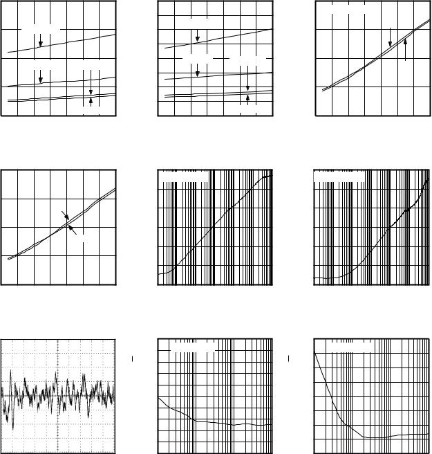
Typical Operating Characteristics (continued)
(VCC = 5V, RL = 10kΩ to VCC/2, TA = +25°C, unless otherwise noted.)
OUTPUT HIGH VOLTAGE vs. TEMPERATURE |
OUTPUT LOW VOLTAGE vs. TEMPERATURE |
SOURCING CURRENT (VCC - VOUT) |
SINKING CURRENT |
|
200 |
|
|
|
|
|
|
toc07 |
|
160 |
|
|
|
|
|
|
toc08 |
|
200 |
|
|
|
|
|
|
|
|
|
|
|
|
|
|
|
|
|
|
||
|
|
|
|
|
|
|
|
|
|
140 |
|
ISINK = 5mA |
|
|
|
MAX9622 |
|
|
|
|
150 |
|
ISOURCE = 5mA |
|
|
|
|
|
120 |
|
|
|
|
|
150 |
||||
|
|
|
|
|
|
|
|
|
|
|
|
|
|
||||||
|
|
|
|
|
|
|
|
|
|
100 |
|
|
|
|
|
|
|
|
|
|
100 |
|
ISOURCE = 1mA |
|
ISOURCE = 0.1mA |
|
80 |
|
ISINK = 1mA |
|
ISINK = 0.1mA |
|
100 |
||||||
|
|
|
|
|
|
|
|
|
|
|
|
|
|
||||||
OUTPUTVOLTAGEHIGH(mV) |
|
|
|
|
|
|
|
MAX9622 |
OUTPUTVOLTAGELOW(mV) |
60 |
|
|
|
|
|
|
CURRENTINPUTBIAS(nA) |
|
|
50 |
|
|
|
|
|
|
40 |
|
|
|
|
|
|
50 |
|||||
|
|
|
|
|
|
|
|
|
|
|
|
|
|
|
|||||
|
|
|
|
|
ISOURCE = 0.01mA |
|
20 |
|
|
|
|
ISINK = 0.01mA |
|
|
|
||||
|
0 |
|
|
|
|
0 |
|
|
|
|
|
|
0 |
||||||
|
|
|
|
|
|
|
|
|
|
|
|
|
|
|
|
|
|||
|
-50 |
-25 |
0 |
25 |
50 |
75 |
100 |
125 |
|
-50 |
-25 |
0 |
25 |
50 |
75 |
100 |
125 |
|
|
|
|
|
TEMPERATURE (°C) |
|
|
|
|
|
TEMPERATURE (°C) |
|
|
|
|
||||||
INPUT BIAS CURRENT vs. TEMPERATURE
|
RLOAD = NO LOAD |
|
|
|
toc09 |
||
|
|
|
|
MAX9622 |
|||
|
|
|
|
|
IN+ |
|
|
|
|
|
|
|
|
IN- |
|
-50 |
-25 |
0 |
25 |
50 |
75 |
100 |
125 |
|
|
TEMPERATURE (°C) |
|
|
|||
INPUT BIAS CURRENT (nA)
INPUT BIAS CURRENT |
COMMON-MODE REJECTION RATIO |
POWER-SUPPLY REJECTION RATIO |
vs. TEMPERATURE |
vs. FREQUENCY |
vs. FREQUENCY |
200 |
|
|
|
|
|
|
toc10 |
|
0 |
RLOAD = NO LOAD |
|
|
|
toc11 |
|
0 |
||
|
|
|
|
|
|
|
|
|
|
|
|
|
|
|||||
150 |
|
|
|
|
|
|
MAX9622 |
|
-20 |
|
|
|
|
|
|
MAX9622 |
|
-20 |
|
|
|
IN+ |
|
|
|
|
|
|
|
|
|
|
|
|
|
|
|
|
|
|
|
|
|
|
(dB) |
-40 |
|
|
|
|
|
|
|
(dB) |
-40 |
|
|
|
|
|
|
|
|
|
|
|
|
|
|
|
|
|
|
||
100 |
|
|
|
|
|
|
|
CMRR |
-60 |
|
|
|
|
|
|
|
PSRR |
-60 |
|
|
|
|
|
IN- |
|
|
|
|
|
|
|
|
|
|
|
||
|
|
|
|
|
|
|
|
-80 |
|
|
|
|
|
|
|
|
-80 |
|
|
|
|
|
|
|
|
|
|
|
|
|
|
|
|
|
|
||
50 |
|
|
|
|
|
|
|
|
|
|
|
|
|
|
|
|
|
|
|
|
|
|
|
|
|
|
|
-100 |
|
|
|
|
|
|
|
|
-100 |
0 |
|
|
|
|
|
|
|
|
-120 |
|
|
|
|
|
|
|
|
-120 |
-50 |
-25 |
0 |
25 |
50 |
75 |
100 |
125 |
|
|
0.01 |
0.1 |
1 |
10 |
100 |
1000 |
10,000 |
|
|
|
|
TEMPERATURE (°C) |
|
|
|
|
|
|
FREQUENCY (kHz) |
|
|
|
|
|||||
RLOAD = NO LOAD |
|
|
|
toc12 |
||
|
|
|
|
|
|
MAX9622 |
0.01 |
0.1 |
1 |
10 |
100 |
1000 |
10,000 |
|
|
FREQUENCY (kHz) |
|
|
||
0.01Hz TO 10Hz INPUT VOLTAGE NOISE |
INPUT VOLTAGE NOISE vs. FREQUENCY |
|
MAX9622 toc13 |
50 |
|
|
toc14 |
|
16 |
|
|
RLOAD = NO LOAD |
|
|
|||
|
|
45 |
|
|
|
||
|
|
|
MAX9622 |
(pA/√Hz) |
14 |
||
|
(nV/√Hz) |
|
|
||||
|
40 |
|
|
||||
|
|
|
12 |
||||
|
|
|
|
|
|
||
|
|
35 |
|
|
|
|
|
400nV/div |
NOISE |
|
|
|
NOISE |
10 |
|
30 |
|
|
|
||||
|
|
|
|
|
|
|
|
|
VOLTAGE |
25 |
|
|
|
CURRENT |
8 |
|
20 |
|
|
|
6 |
||
|
|
|
|
|
|
||
|
|
15 |
|
|
|
|
|
|
INPUT |
|
|
|
INPUT |
4 |
|
|
10 |
|
|
|
|||
|
|
|
|
|
|
||
|
|
|
|
|
|
2 |
|
|
|
5 |
|
|
|
|
|
|
|
|
|
|
|
|
|
|
|
0 |
|
|
|
|
0 |
1s/div |
|
10 |
100 |
1000 |
10,000 |
|
|
|
|
|
FREQUENCY (Hz) |
|
|
|
|
INPUT CURRENT NOISE vs. FREQUENCY
|
RLOAD = NO LOAD |
|
toc15 |
|
|
MAX9622 |
|
|
|
|
|
10 |
100 |
1000 |
10,000 |
|
FREQUENCY (Hz) |
|
|
www.maximintegrated.com |
Maxim Integrated │ 4 |
MAX9622 |
Precision, High-Bandwidth Op Amp |
Typical Operating Characteristics (continued) |
|
|
|
|
|
|
|
|
|
|
(VCC = 5V, RL = 10kΩ to VCC/2, TA = +25°C, unless otherwise noted.) |
|
|
|
|
|
|
|
|
|
|
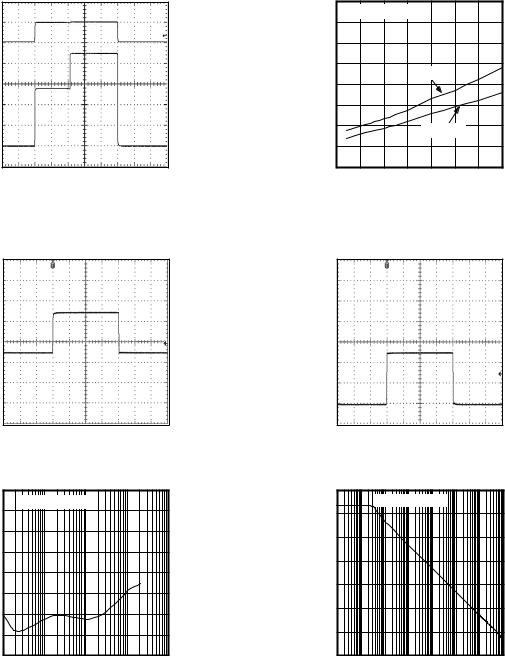
TURN-ON RESPONSE |
|
|
QUIESCENT CURRENT vs. TEMPERATURE |
|||||||
VIN = 22.34mV, AV = 100V/V |
|
|
|
VCC = 5V, VOUT IN SATURATION |
|
|||||
MAX9622 toc16 |
|
2.0 |
|
|
|
|
|
|
|
toc17 |
VCC |
|
RLOAD = NO LOAD |
|
|
|
|||||
|
|
|
|
|
||||||
(mA) |
1.6 |
|
|
|
|
|
|
|
MAX9622 |
|
GND |
|
|
|
|
|
|
|
|||
5V/div |
CURRENT |
1.8 |
|
|
|
|
|
|
|
|
|
1.4 |
|
|
|
VOUT = HIGH |
|
|
|||
|
|
|
|
|
|
|
||||
|
|
1.2 |
|
|
|
|
|
|||
|
QUIESCENT |
|
|
|
|
VOUT = LOW |
|
|
||
500mV/div |
0.8 |
|
|
|
|
|
|
|||
VOUT |
|
1.0 |
|
|
|
|
|
|
|
|
|
|
|
|
|
|
|
|
|
|
|
GND |
|
0.6 |
|
|
|
|
|
|
|
|
|
|
|
|
|
|
|
|
|
|
|
|
|
0.4 |
-50 |
-25 |
0 |
25 |
50 |
75 |
100 |
125 |
|
|
|
||||||||
|
|
|
|
|
TEMPERATURE (°C) |
|
|
|||
OUTPUT RECOVERY FROM SATURATION |
OUTPUT RECOVERY FROM SATURATION |
VOUT SATURATED TO POSITIVE RAIL |
VOUT SATURATED TO NEGATIVE RAIL |
MAX9622 toc18 |
MAX9622 toc19 |
VOUT
1V/div
GND
4µs/div
TOTAL HARMONIC DISTORTION
PLUS NOISE vs. FREQUENCY
|
-40 |
RLOAD = NO LOAD |
|
toc20 |
|
|
|
|
|||
|
-50 |
|
MAX9622 |
||
|
|
|
|
||
|
-60 |
|
|
|
|
|
|
|
|
|
|
(%) |
-70 |
|
|
|
|
|
|
|
|
|
|
THD+N |
-80 |
|
|
|
|
-90 |
|
|
|
|
|
|
|
|
|
|
|
|
-100 |
|
|
|
|
|
-110 |
|
|
|
|
|
-120 |
|
|
|
|
|
10 |
100 |
1000 |
10,000 |
100,000 |
|
|
|
FREQUENCY (kHz) |
|
|
VOUT
1V/div
GND
4µs/div
OPEN-LOOP GAIN vs. FREQUENCY
|
120 |
|
RLOAD = NO LOAD |
toc21 |
||
|
|
|
||||
|
|
|
MAX9622 |
|||
|
100 |
|
|
|
|
|
|
|
|
|
|
|
|
(dB) |
80 |
|
|
|
|
|
GAIN |
60 |
|
|
|
|
|
LOOP |
40 |
|
|
|
|
|
OPEN- |
|
|
|
|
|
|
20 |
|
|
|
|
|
|
|
|
|
|
|
|
|
|
0 |
|
|
|
|
|
|
-20 |
|
|
|
|
|
|
0.01 |
0.1 |
1 |
10 |
100 |
1000 10,000 100,000 |
|
|
|
FREQUENCY (kHz) |
|||
www.maximintegrated.com |
Maxim Integrated │ 5 |

MAX9622 |
Precision, High-Bandwidth Op Amp |
Typical Operating Characteristics (continued)
(VCC = 5V, RL = 10kΩ to VCC/2, TA = +25°C, unless otherwise noted.)
LARGE-SIGNAL RESPONSE
MAX9622 toc22
AV = 1V/V
OUTPUT
1µs/div
CAPACITIVE LOADING STABILITY vs. ISOLATION RESISTANCE, AV = 1V/V
|
50 |
toc24 |
|
|
45 |
||
|
MAX9622 |
||
Ω) |
40 |
||
( |
|
||
RESISTANCE |
35 |
|
|
30 |
STABLE |
||
25 |
|||
|
|||
ISOLATION |
20 |
|
|
15 |
|
||
10 |
|
||
|
UNSTABLE |
||
|
5 |
||
|
|
||
|
0 |
|
|
|
0 |
100 200 300 400 500 600 700 800 900 1000 |
|
|
|
CAPACITANCE (pF) |
SMALL-SIGNAL RESPONSE
MAX9622 toc23
AV = 1V/V
OUTPUT 500mV/div
4µs/div
PARALLEL CAPACITIVE LOADING
10,000 |
VCC = 5V |
toc25 |
|
|
|
||
|
|
MAX9622 |
|
|
|
|
|
(Ω) |
|
|
|
LOAD RESISTANCE |
|
UNSTABLE |
|
1000 |
|
|
|
|
STABLE |
|
|
100
50 |
75 |
100 |
125 |
150 |
|
|
CAPACITANCE (pF) |
|
|
CROSSTALK vs. FREQUENCY
|
0 |
RLOAD = NO LOAD |
|
toc26 |
||
|
|
|
||||
|
-20 |
|
MAX9622 |
|||
|
|
|
|
|
||
|
|
|
|
|
|
|
(dB) |
-40 |
|
|
|
|
|
|
|
|
|
|
|
|
CROSSTALK |
-60 |
|
|
|
|
|
-80 |
|
|
|
|
|
|
|
|
|
|
|
|
|
|
-100 |
|
|
|
|
|
|
-120 |
|
|
|
|
|
|
-140 |
|
|
|
|
|
|
0.1 |
1 |
10 |
100 |
1000 |
10,000 100,000 |
|
|
|
FREQUENCY (kHz) |
|
||
www.maximintegrated.com |
Maxim Integrated │ 6 |

MAX9622 |
Precision, High-Bandwidth Op Amp |
Pin Configuration
TOP VIEW
|
|
+ |
|
|
|
MAX9622 |
|
IN+ |
1 |
5 |
VCC |
GND |
2 |
|
|
IN- |
3 |
4 |
OUT |
|
|
SC70 |
|
Pin Description
PIN |
NAME |
FUNCTION |
|
|
|
1 |
IN+ |
Positive Input |
|
|
|
2 |
GND |
Ground |
|
|
|
3 |
IN- |
Negative Input |
|
|
|
4 |
OUT |
Output |
|
|
|
5 |
VCC |
Positive Power Supply. Bypass with a 0.1µF capacitor to ground. |
www.maximintegrated.com |
Maxim Integrated │ 7 |
MAX9622 |
Precision, High-Bandwidth Op Amp |
Detailed Description
The MAX9622 is a power-efficient, high-speed op amp ideal for capturing fast edges in a wide variety of signal processing applications.
It precisely calibrates its VOS on power-up to eliminate the effects of package stresses, power supplies, and temperature.
Applications Information
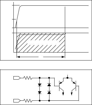
Power-Up Autotrim
The MAX9622 features power-up autotrimming that allows the devices to achieve less than 100µV of input offset voltage. The startup sequence takes approximately 4ms to complete after the supply voltage exceeds an internal threshold of 1.8V. During this time, the inputs and outputs are connected to an auxiliary amplifier that has an input offset of 5mV (typ). As soon as the autotrimming is completed, the inputs and outputs switch from the auxiliary amplifier to the calibrated amplifier. The calibration settings hold until the supply voltage drops below an internal threshold of 1.4V. This could be used to recalibrate the amplifier. The supply current of the part increases to about 2.5mA during the power-up autotrim period. Use good supply decoupling with low ESR capacitors.
Active Filters
The MAX9622 is ideal for a wide variety of active filter circuits that make use of their wide output voltage swings and large bandwidth capabilities. The Typical Application Circuit shows a multiple feedback active filter circuit example with a 100kHz corner frequency. At low frequencies, the amplifier behaves like a simple low-distortion inverting amplifier gain = -1, while its high bandwidth gives excellent stopband attenuation above its corner frequency. See the Typical Application Circuit.
Input Differential Voltage Protection
During normal op-amp operation, the inverting and noninverting inputs of the MAX9622 are at essentially the same voltage. However, either due to fast input voltage transients or due to loss of negative feedback, these pins can be forced to different voltages. Internal back-to-back diodes and series resistors protect input-stage transistors from large input differential voltages (see Figure 2).
IN+ and INcan survive any voltage between the powersupply rails.
This op amp has been designed to exhibit no phase inversion to overdriven inputs.
5V |
|
|
VCC |
|
|
1.8V |
|
|
0V |
|
|
2V |
|
|
VOUT |
|
CALIBRATED |
AUXILIARY AMPLIFIER ACTIVE |
AMPLIFIER |
|
|
|
ACTIVE |
0V |
|
|
|
4ms |
|
Figure 1. Autotrim Timing Diagram
100Ω |
100Ω |
Figure 2. Input Protection Circuit
www.maximintegrated.com |
Maxim Integrated │ 8 |
MAX9622 |
Precision, High-Bandwidth Op Amp |
Package Information
For the latest package outline information and land patterns (footprints), go to www.maximintegrated.com/packages. Note that a “+”, “#”, or “-” in the package code indicates RoHS status only. Package drawings may show a different suffix character, but the drawing pertains to the package regardless of RoHS status.
PACKAGE TYPE |
PACKAGE CODE |
OUTLINE NO. |
LAND PATTERN NO. |
|
|
|
|
5 SC70 |
X5+1 |
21-0076 |
90-0188 |
|
|
|
|
www.maximintegrated.com |
Maxim Integrated │ 9 |
MAX9622 |
Precision, High-Bandwidth Op Amp |
Revision History
REVISION |
REVISION |
DESCRIPTION |
PAGES |
|
NUMBER |
DATE |
CHANGED |
||
|
||||
0 |
9/10 |
Initial release |
— |
|
|
|
|
|
|
1 |
4/15 |
Removed automotive reference from data sheet |
1 |
|
|
|
|
|
For pricing, delivery, and ordering information, please contact Maxim Direct at 1-888-629-4642, or visit Maxim Integrated’s website at www.maximintegrated.com.
Maxim Integrated cannot assume responsibility for use of any circuitry other than circuitry entirely embodied in a Maxim Integrated product. No circuit patent licenses are implied. Maxim Integrated reserves the right to change the circuitry and specifications without notice at any time. The parametric values (min and max limits) shown in the Electrical Characteristics table are guaranteed. Other parametric values quoted in this data sheet are provided for guidance.
Maxim Integrated and the Maxim Integrated logo are trademarks of Maxim Integrated Products, Inc. |
© 2015 Maxim Integrated Products, Inc. │ 10 |