

5R55W
.pdfINTRODUCTION
FORD 5R55S
FORD 5R55W
Updated
March, 2004
The Ford 5R55S and 5R55W transmissions are both very similar in design to the Ford 5R55N transmission and use electronic shift controls. The 5R55S/W are both "Syncrounous" units, as they do not use the intermediate clutch and intermediate sprag that the 5R55N incorporates. The Ford 5R55S and 5R55W transmissions were introduced in 2002, found in the Ford Explorer and Mercury Mountaineer vehicles, and are available in both 2WD and 4WD configurations. For model year 2003 they are also in the Lincoln LS, Lincoln Aviator and Ford Thunderbird. They are designed for operation in longitudinal powertrains for rear wheel drive vehicles.
5R55S Gear Ratios
1st Gear = 3.22 2nd Gear =2.29 3rd Gear = 1.54 4th Gear = 1.00 5th Gear = 0.71 Reverse = 3.07
5R55W Gear Ratios
1st Gear = 3.22 2nd Gear =2.41 3rd Gear = 1.54 4th Gear = 1.00 5th Gear = 0.75 Reverse = 3.07
We wish to thank Ford Motor Company for the information and illustrations that have made this booklet possible.
No part of any ATSG publication may be reproduced, stored in any retrieval system or transmitted in any form or by any means, including but not limited to electronic, mechanical, photocopying, recording or otherwise, without written permission of Automatic Transmission Service Group. This includes all text illustrations, tables and charts.
The information and part numbers contained in this booklet have been carefully compiled from industry sources known for their reliability, but ATSG does not guarantee its accuracy.
DALE ENGLAND |
Copyright © ATSG 2004 |
JIM DIAL |
|
|
TECHNICAL CONSULTANT |
||
FIELD SERVICE CONSULTANT |
|||
WAYNE COLONNA |
|
ED KRUSE |
|
TECHNICAL SUPERVISOR |
|
TECHNICAL CONSULTANT |
|
PETER LUBAN |
|
GREGORY LIPNICK |
|
TECHNICAL CONSULTANT |
|
TECHNICAL CONSULTANT |
|
JON GLATSTEIN |
|
DAVID CHALKER |
|
TECHNICAL CONSULTANT |
|
TECHNICAL CONSULTANT |
|
JERRY GOTT |
|
STANTON ANDERSON |
|
TECHNICAL CONSULTANT |
|
TECHNICAL CONSULTANT |
|
GERALD CAMPBELL |
|
ROLAND ALVAREZ |
|
TECHNICAL CONSULTANT |
|
TECHNICAL CONSULTANT |
|
|
|
MIKE SOUZA |
|
|
|
TECHNICAL CONSULTANT |
|
AUTOMATIC TRANSMISSION SERVICE GROUP |
|||
|
9200 S. DADELAND BLVD. SUITE 720 |
||
|
MIAMI, FLORIDA 33156 |
|
|
|
(305) 670-4161 |
|
1 |

GOTO PAGE
FORD MOTOR CO . 5R55W/S
INDEX PREVIOUS MENU
5R55W/S TRANSMISSION IDENTIFICATION .............................................................................................. |
3 |
COMPONENT APPLICATION CHART ........................................................................................................... |
4 |
SOLENOID APPLICATION AND RESISTANCE CHARTS ........................................................................... |
5 |
SOLENOID BODY PIN IDENTIFICATION .................................................................................................... |
6 |
GENERAL DESCRIPTION AND OPERATION .............................................................................................. |
7 |
MANUAL SHIFT SELECTOR OPERATION ................................................................................................... |
9 |
BATTERY JUNCTION BOX FUSE AND RELAY LOCATIONS ..................................................................... |
10 |
CENTRAL JUNCTION BOX FUSE LOCATIONS ........................................................................................... |
10 |
DIGITAL TRANSMISSION RANGE SENSOR ................................................................................................ |
11 |
VARIOUS CONNECTOR AND PIN IDENTIFICATION ................................................................................. |
12 |
WIRING SCHEMATIC ....................................................................................................................................... |
13 |
PCM LOCATION ................................................................................................................................................. |
15 |
TRANSMISSION COMPONENT RESISTANCE CHART THROUGH PCM CONNECTOR ....................... |
16 |
DIAGNOSTIC TROUBLE CODE CHART AND DESCRIPTION .................................................................. |
18 |
LINE PRESSURE TESTS .................................................................................................................................. |
21 |
CHECKING TRANSMISSION FLUID LEVEL ............................................................................................... |
22 |
TRANSMISSION DISASSEMBLY .................................................................................................................... |
24 |
COMPONENT REBUILD SECTION......... |
|
OIL PUMPASSEMBLY .................................................................................................................................. |
39 |
COAST CLUTCH HOUSING ......................................................................................................................... |
43 |
OVERDRIVE CARRIER AND OVERDRIVE SPRAGASSEMBLY ............................................................ |
47 |
DIRECT CLUTCH HOUSING ....................................................................................................................... |
49 |
FORWARD CLUTCH HOUSING .................................................................................................................. |
52 |
CENTER SUPPORT ASSEMBLY .................................................................................................................. |
57 |
LOW SPRAG AND REVERSE DRUM ASSEMBLY ..................................................................................... |
58 |
REAR RING GEAR AND HUB ASSEMBLY ................................................................................................. |
58 |
FRONT AND REAR PLANETARY CARRIER ASSEMBLY ........................................................................ |
60 |
SUN GEAR AND SHELLASSEMBLY .......................................................................................................... |
61 |
FRONT RING GEAR AND HUB ASSEMBLY .............................................................................................. |
61 |
VALVE BODYASSEMBLY ............................................................................................................................. |
65 |
CHECKBALL LOCATIONS ........................................................................................................................... |
66 |
REVERSE SERVO ASSEMBLY ..................................................................................................................... |
68 |
SOLENOID BODY DIFFERENCES ............................................................................................................. |
72 |
SOLENOID BODYASSEMBLY ..................................................................................................................... |
73 |
4WD ADAPTER HOUSING AND PARKING PAWLASSEMBLY .............................................................. |
74 |
TRANSMISSION CASE ASSEMBLY ............................................................................................................ |
76 |
FINAL TRANSMISSION ASSEMBLY .............................................................................................................. |
79 |
REAR END CLEARANCE PROCEDURES ...................................................................................................... |
84 |
FRONT END CLEARANCE PROCEDURES ................................................................................................... |
93 |
2WD EXTENSION HOUSINGASSEMBLY SECTION ................................................................................. |
100 |
BOLT SIZE AND LENGTH CHART ................................................................................................................ |
105 |
SPECIAL SERVICE TOOLS ............................................................................................................................. |
106 |
TORQUE SPECIFICATIONS ............................................................................................................................ |
108 |
5R55N VERSUS 5R55W/S DIFFERENCES ................................................................................................... |
108 |
AUTOMATIC TRANSMISSION SERVICE GROUP
9200 S. DADELAND BLVD. SUITE 720
MIAMI, FLORIDA 33156
(305) 670-4161
Copyright © ATSG 2004
2
Technical Service Information
|
|
|
FORD 5R55W/S |
5 = 5 Forward Speeds |
|
||||
|
|
|
|
|
|
|
|||
|
|
|
|
|
|
R = Rear Wheel Drive |
|
||
|
|
|
|
|
|
55 } = Relative Torque Capacity |
|||
|
|
|
|
|
|
S or W = Syncrounous |
|||
|
|
|
|
F |
ord |
|
|
|
|
|
|
|
|
|
Ford |
|
|
|
|
|
|
|
|
|
|
AA-397221PFL- |
|
|
|
|
|
|
|
|
|
AL |
|
|
|
|
|
|
|
|
1600 |
UTR |
|
|
|
|
|
|
|
|
NE |
|
|
|
|
|
|
|
|
|
|
|
|
|
|
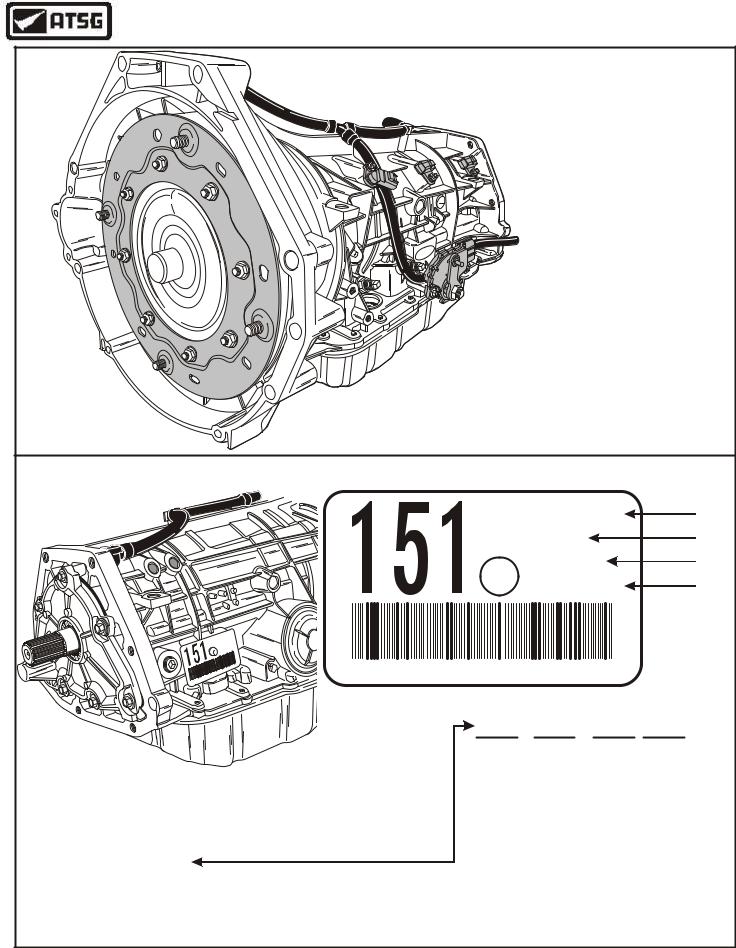
I.D. TAG INFORMATION FOUND ON RIGHT REAR SIDE OF TRANSMISSION |
|||||||||
|
|
|
|
|
|
|
2L2P-DA |
1 |
|
|
|
|
|
|
|
|
BDX-A |
|
2 |
|
|
|
|
|
|
|
004361 |
3 |
|
|
|
|
|
|
|
|
BD-2C17 |
4 |
|
|
|
|
A |
|
|
|
|
|
|
|
|
P-D |
|
|
|
|
|
|
|
|
|
2L2 |
|
|
|
|
|
|
|
|
|
-A |
|
|
|
|
|
|
|
|
|
DX |
1 |
|
|
|
|
|
|
|
|
B |
|
|
|
|
|
|
|
|
|
36 |
|
|
|
|
|
|
|
|
|
04 |
17 |
|
|
|
|
|
|
|
|
0 |
|
|
|
|
|
|
|
|
|
-9H |
|
|
|
|
|
|
|
|
|
BD |
|
|
|
|
|
|
|
|
|
4361 |
R J L - B |
004361 |
|
|
|
||
BDX |
-A |
00 |
|
|
|
||||
|
|
|
|
|
|
|
|
|
|
|
|
|
|
|
|
|
Year |
Month |
Day |
|
|
|
|
|
|
BD- |
9 |
C |
17 |
|
|
|
|
|
|
Build |
9=1999 |
A=Jan |
|
|
|
|
|
|
|
Date |
0=2000 |
B=Feb |
|
|
|
|
|
|
|
|
1=2001 |
C=Mar |
|
1. Part Number, Basic = 7000 |
(Example 2L2Z-7000-DA) |
|
|
|
2=2002 |
D=Apr |
|
||
|
|
|
3=2003 |
E=May |
|
||||
2. Transmission Model Code |
|
|
|
|
|
F=Jun |
|
||
3. Serial Number |
|
|
|
|
|
|
|
G=Jul |
|
4. Build Date (YMDD) |
|
|
|
|
|
|
|
H=Aug |
|
|
|
|
|
|
|
|
J=Sep |
|
|
|
|
|
|
|
|
|
|
|
|
|
|
|
|
|
|
|
|
K=Oct |
|
|
|
|
|
|
|
|
|
L=Nov |
|
|
|
|
|
|
|
|
|
M=Dec |
|
|
|
|
|
|
|
|
Copyright © 2004 ATSG |
||
Figure 1
AUTOMATIC TRANSMISSION SERVICE GROUP |
3 |
|
Technical Service Information
FORD 5R55W/S COMPONENT APPLICATION CHART
|
FWD |
DIR |
COAST |
O/D |
INT |
L/R |
O/D |
LOW |
TCS |
5R55W |
5R55S |
RANGE |
CLUT |
CLUT |
CLUT |
BAND |
BAND |
BAND |
SPRAG |
SPRAG |
Switch |
RATIO |
RATIO |
Park |
|
|
|
|
|
|
|
|
|
|
|
Reverse |
|
ON |
|
|
|
ON |
HOLD |
|
|
3.07 |
3.07 |
Neutral |
|
|
|
|
|
|
|
|
|
|
|
"D"-1st Gear |
ON |
|
|
|
|
|
HOLD |
HOLD |
OFF |
3.22 |
3.22 |
"D"-2nd Gear |
ON |
|
|
ON |
|
|
|
HOLD |
OFF |
2.41 |
2.29 |
"D"-3rd Gear |
ON |
|
|
|
ON |
|
HOLD |
|
OFF |
1.54 |
1.54 |
"D"-4th Gear |
ON |
ON |
|
|
|
|
HOLD |
|
OFF |
1.00 |
1.00 |
"D"-5th Gear |
ON |
ON |
|
ON |
|
|
|
|
OFF |
0.75 |
0.71 |
"D"-1st Gear |
ON |
|
ON |
|
|
|
HOLD |
HOLD |
ON |
3.22 |
3.22 |
"D"-2nd Gear |
ON |
|
|
ON |
|
|
|
HOLD |
ON |
2.41 |
2.29 |
"D"-3rd Gear |
ON |
|
ON |
|
ON |
|
HOLD |
|
ON |
1.54 |
1.54 |
"D"-4th Gear |
ON |
ON |
ON |
|
|
|
HOLD |
|
ON |
1.00 |
1.00 |
"3"-3rd Hold * |
ON |
|
ON |
|
ON |
|
HOLD |
|
|
1.54 |
1.54 |
"2"-2nd Hold ** |
ON |
|
|
ON |
|
ON |
|
HOLD |
|
2.41 |
2.29 |
|
|
|
|
|
|
|
|
|
|
|
|
"1"-1st Hold *** |
ON |
|
ON |
|
|
ON |
HOLD |
HOLD |
|
3.22 |
3.22 |
|
|
|
|
|
|
|
|
|
|
|
|
* Manual "3" is 3rd gear starts and hold.
**Manual "2" is 2nd gear starts and hold.
***Manual "1" provides 1st gear operation only.
Coast |
Overdrive |
|
|
Clutch |
|
|
|
Band |
|
|
|
|
|
|
|
|
Direct |
Forward |
Low/Reverse |
|
Intermediate |
||
|
Clutch |
Clutch |
Band |
|
Band |
||
|
Overdrive |
|
|
|
Sprag |
|
Low/Reverse |
|
|
|
Sprag |
Copyright © 2004 ATSG
Figure 2
4 |
AUTOMATIC TRANSMISSION SERVICE GROUP |
|

Technical Service Information
FORD 5R55W/S SOLENOID APPLY CHART
Range And Gear Commanded |
|
Shift |
Shift |
Shift |
|
Shift |
|
Pres Cont |
Pres Cont |
Pres Cont |
TCC |
||||
Sol. "A" |
Sol. "B" |
Sol. "C" |
Sol. "D" |
Sol. "A" |
Sol. "B" |
Sol. "C" |
Solenoid |
||||||||
|
|
|
|
|
|
|
|
|
|
|
|
|
|
|
|
|
Park/Neutral |
|
ON |
|
|
|
ON |
|
"L" |
|
"V" |
"L" |
|
|
|
|
Reverse |
|
ON |
|
|
|
ON |
|
"L" |
|
"H" |
"H" |
|
|
|
|
"D" - 1st Gear |
|
ON |
|
|
|
ON |
|
"V" |
|
"L" |
"L" |
|
|
|
|
"D" - 2nd Gear |
|
ON |
|
ON |
|
ON |
|
"L" |
|
"V" |
"L" |
** |
|
|
|
"D" - 3rd Gear |
|
ON |
ON |
|
|
ON |
|
"V" |
|
"L" |
"L" |
** |
|
|
|
"D" - 4th Gear |
|
|
|
|
|
ON |
|
"V" |
|
"L" |
"H" |
** |
|
|
|
"D" - 5th Gear |
|
|
|
ON |
|
ON |
|
"V" |
|
"V" |
"H" |
** |
|
|
|
|
|
|
|
|
|
|
|
|
|
|
|
|
|
|
|
"D" - 1st Gear |
|
ON |
|
|
|
ON |
|
"V" |
|
"L" |
"L" |
|
|
|
|
"D" - 2nd Gear |
|
ON |
|
ON |
|
ON |
|
"L" |
|
"V" |
"L" |
** |
|
|
|
"D" - 3rd Gear |
|
ON |
ON |
|
|
ON |
|
"V" |
|
"L" |
"L" |
** |
|
|
|
"D" - 4th Gear |
|
|
|
|
|
|
|
|
"V" |
|
"V" |
"H" |
** |
|
|
|
|
|
|
|
|
|
|
|
|
|
|
|
|
|
|
"3" - 3rd Gear (Hold) |
|
ON |
ON |
|
|
|
|
|
"V" |
|
"V" |
"L" |
|
|
|
|
|
|
|
|
|
|
|
|
|
|
|
|
|
|
|
"2" - 2nd Gear (Hold) |
|
ON |
|
ON |
|
|
|
|
"V" |
|
"V" |
"L" |
|
|
|
|
|
|
|
|
|
|
|
|
|
|
|
|
|
|
|
"1" - 1st Gear (Hold) |
|
ON |
|
|
|
|
|
|
"V" |
|
"V" |
"L" |
|
|
|
"L" = Lower Line Pressure |
|
|
|
|
|
|
|
|
|
|
|
|
|
|
|
"V" = Variable Line Pressure |
|
|
|
|
|
|
|
|
|
|
|
|
|
|
|
"H" = Higher Line Pressure |
|
|
|
|
|
|
|
|
|
|
|
|
|
|
|
** = TCC may be On, and is dependent on vehicle speed and throttle position |
|
|
|
|||||||||||
|
CASE CONNECTOR PIN IDENTIFICATION |
|
|
|
|
|
|||||||||
|
|
|
AND RESISTANCE CHARTS |
|
|
|
|
|
|||||||
|
|
|
|
|
|
|
|
|
|
||||||
|
Solenoid Resistance Chart |
|
|
|
|
|
TOT Sensor Resistance Chart |
|
|||||||
|
|
|
Connector |
Resistance |
|
|
|
0°F-31°F = 284k - 100k Ohms |
|
||||||
|
Component |
Terminals |
In Ohms |
|
|
|
|
|
|
|
|
|
|||
|
|
|
|
32°F-68°F = 100k - 37k Ohms |
|
||||||||||
|
Shift Solenoid "A" |
3 And 16 |
16-45 |
|
|
|
|
|
|
|
|
|
|
||
|
|
|
|
|
69°F-104°F = 37k - 16k Ohms |
|
|||||||||
|
Shift Solenoid "B" |
3 And 15 |
16-45 |
|
|
|
|
|
|
|
|
|
|
||
|
|
|
|
|
105°F-158°F = 16k - 5k Ohms |
|
|||||||||
|
Shift Solenoid "C" |
3 And 6 |
16-45 |
|
|
|
|
|
|
|
|
|
|
||
|
|
|
|
|
159°F-194°F = 5k - 2.7k Ohms |
|
|||||||||
|
Shift Solenoid "D" |
3 And 5 |
16-45 |
|
|
|
|
|
|
|
|
|
|
||
|
|
|
|
|
195°F-230°F = 2.7k - 1.5k Ohms |
|
|||||||||
|
Pressure Control Solenoid "A" |
3 And 11 |
3.3-7.5 |
|
|
|
|
|
|
|
|
|
|||
|
|
|
|
231°F-266°F = 1.5k - 0.8k Ohms |
|
||||||||||
|
Pressure Control Solenoid "B" |
3 And 1 |
3.3-7.5 |
|
|
|
|
|
|
|
|
|
|||
|
|
|
267°F-302°F = 0.8k - 0.54k Ohms |
|
|||||||||||
|
Pressure Control Solenoid "C" |
3 And 4 |
3.3-7.5 |
|
|
|
|
|
|
|
|
|
|||
|
|
|
|
Refer To Figure 4 For |
|
|
|||||||||
|
TCC Solenoid |
3 And 14 |
9-16 |
|
|
|
|
|
|
||||||
|
|
|
|
|
|
|
|
|
|
Case Connector Pin |
|
|
|||
|
|
|
|
|
|
|
|
|
|
|
|
||||
|
|
|
|
|
|
|
|
|
|
|
Identification |
|
|
||
|
TOT Sensor |
2 And 12 |
See Chart |
|
|
|
|
|
Copyright © 2004 ATSG |
||||||
|
|
|
|
|
|
|
|
|
|
|
|
||||
Figure 3
AUTOMATIC TRANSMISSION SERVICE GROUP |
5 |
|
Technical Service Information
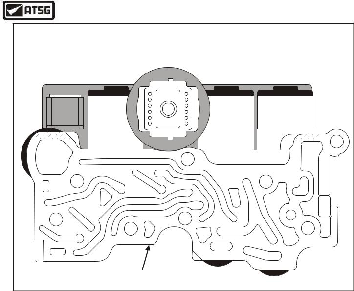
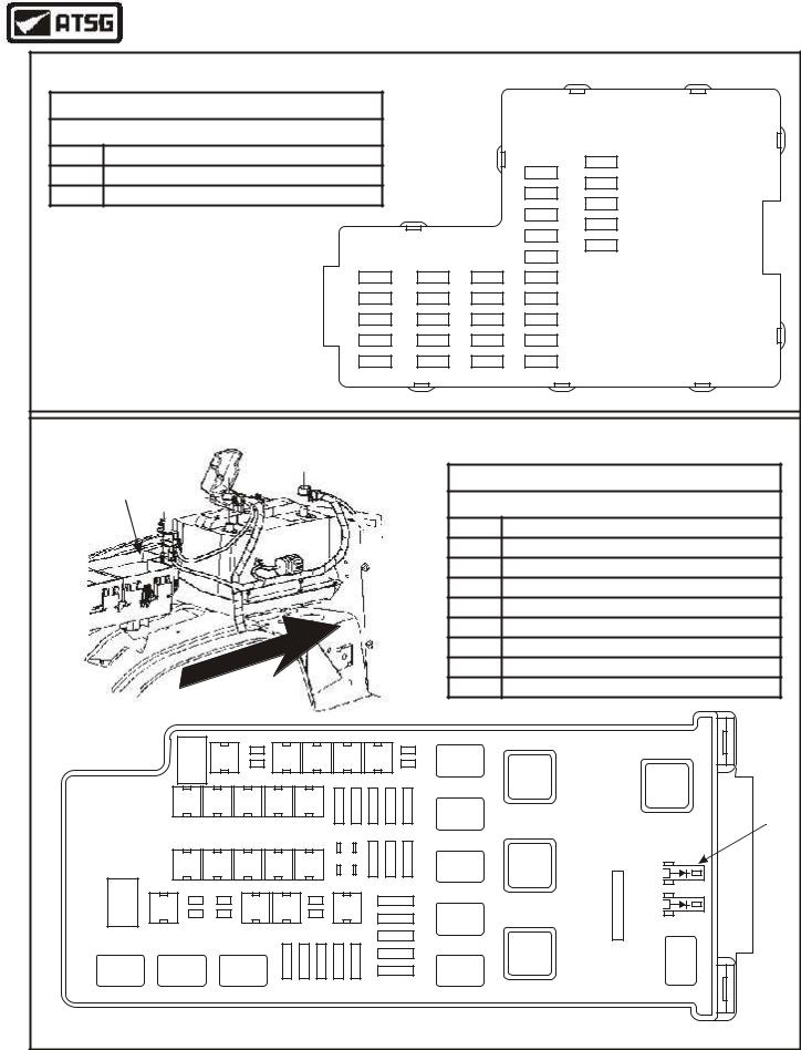
CASE CONNECTOR PIN IDENTIFICATION |
|
View Looking Into Transmission |
|
Case Connector |
|
11 |
1 |
16 |
6 |
SOLENOID PACK |
|
ASSEMBLY |
Copyright © 2004 ATSG |
Figure 4
"FAIL-SAFE" DESCRIPTION AND OPERATION
If the Powertrain Control Module (PCM) detects an input sensor or signal fault, it may use Failure Management Effects Mode (FMEM) strategy and provide a substitute signal or value.
If the transmission totally loses electronic control, it will operate in a Fail-Safe mode with all of the following features:
 Maximum line pressure in all transmission shifter positions.
 Fully functional "P", "R" and "N" transmission shifter positions.
 Operation in 4th gear only with coast braking when the selector is in the "D", "3", "2", or "1" positions.
 Torque Converter Clutch (TCC) will be released in all positions.
6 |
AUTOMATIC TRANSMISSION SERVICE GROUP |
|

Technical Service Information
GENERAL DESCRIPTION AND OPERATION
The 5R55W/S is a fully automatic rear wheel drive transmission. It provides Park, Reverse, Neutral, and five forward speeds with 5th gear being overdrive
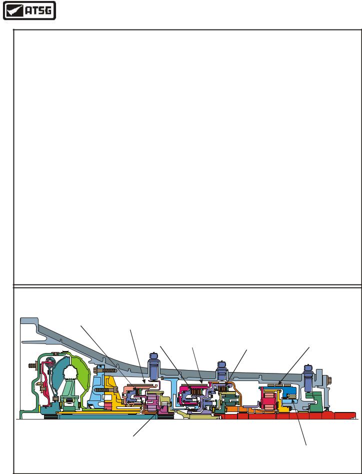
Internally it looks similar to the previous 5R55E transmission, but there are very few minor components that are actually the same, so be very cautious during the rebuild process. The major components used in this unit are as follows:
3 Multi-Plate Clutch Packs
Coast Clutch
Direct Clutch (Single Sided)
Forward Clutch
2 One-Way Clutches
Overdrive Sprag Clutch
Low Sprag Clutch
3 Brake Bands
Overdrive Band
Intermediate Band
Low/Reverse Band
3 Compound Planetary Gear Sets
Overdrive Planetary Set
Forward Planetary Set
Rear Planetary Set
The shift pattern is controlled electronically with four (On-Off) solenoids that recieve a ground signal from the PCM (Powertrain Control Module). The PCM will vary shift points, as it is constantly interpreting numerous electronic signals from various operational sensors located on the vehicle and inside the transmission.
Line pressure and shift feel are also controlled electronically with three Pressure Control solenoids, referred to as PCA, PCB, and PCC. The PCM varies the current to the pressure control solenoids and Ford refers to them as Variable Force Solenoids.
The PCM also controls application of the converter clutch and apply feel electronically, with a TCC solenoid, which is also Variable Force style.
All solenoids are incorporated in the "Solenoid Body", located on the valve body, and are not serviced seperately. You must purchase the entire solenoid body assembly, if necessary.
ELECTRONIC COMPONENTS
The PCM also receives input signals from various sensors and switches, located internally and externally, that affect proper transmission operation. The following will provide a brief description of each of the sensors and actuators used for transmission operations.
AIR CONDITIONING CLUTCH
This switch is located on the suction accum/drier and when the A/C is engaged, operating pressures are adjusted to compensate for the additional engine load.
BRAKE PEDAL POSITION (BPP) SWITCH
This switch is located on the brake pedal and tells the PCM when the brakes are applied. The TCC is disengaged when the brakes are applied. The BPP switch closes when the brakes are applied and open when they are released.
ENGINE COOLANT TEMPERATURE (ECT) SENSOR
This sensor detects temperature of engine coolant and supplies the information to the PCM. The PCM uses this information to control Torque Converter Clutch (TCC) operation.
ELECTRONIC IGNITION (EI) SYSTEM
The ignition control module generates a Profile Ignition Pickup (PIP) signal (engine rpm) and sends it to the PCM. The PCM uses PIP signal in the transmission strategy for WOT shift control, TCC control and operating pressures.
INTAKE AIR TEMPERATURE (IAT) SENSOR
The Intake Air Temperature (IAT) sensor, located in the air cleaner outlet tube, is also used in the transmission strategy to determine control pressures.
MASS AIR FLOW (MAF) SENSOR
The Mass Air Flow (MAF) sensor, located in the air cleaner inlet tube, measures the amount of air flowing into the engine and sends this information (engine load) to the PCM. For transmission strategies the MAF is used to regulate electronic pressure control, shift timing and torque converter clutch scheduling.
Continued On Next Page
Copyright © 2004 ATSG
AUTOMATIC TRANSMISSION SERVICE GROUP |
7 |
|

Technical Service Information
ELECTRONIC COMPONENTS (Cont'd)
TRANSMISSION CONTROL SWITCH (TCS)
The Transmission Control Switch (TCS), located within the manual shift selector assembly, as shown in Figure 5, is a momentary contact switch. When this switch is pressed, overdrive (5th gear) will be canceled. After the TCS has been pressed to request overdrive cancel, the PCM turns ON the Transmission Control Indicator Lamp (TCIL) to indicate that overdrive cancel mode is activated.
TRANSMISSION CONTROL INDICATOR LAMP (TCIL)
The Transmission Control Indicator Lamp (TCIL), is located on the manual shift lever, as shown in Figure 5, or in the instrument panel and illuminates when the TCS switch is pressed. When the TCIL is "ON", overdrive is OFF or canceled.
The PCM will also "Flash" the TCIL when it detects a fault in one of the solenoids or monitered sensors or switches.
THROTTLE POSITION SENSOR (TPS)
The Throttle Position Sensor is a potentiometer located on the throttle body and is used to detect throttle plate position and send this information to the PCM. The PCM uses this information for shift scheduling, pressure control and TCC control.
DIGITAL TRANSMISSION RANGE (TR) SENSOR
The Digital Transmission Range (TR) sensor is located on the outside of the transmission at the manual shift lever. The digital TR sensor completes the start circuit in Park and Neutral, and the back-up lamp circuit in Reverse. The digital TR sensor also opens or closes a set of four switches that are monitered by the PCM to determine the position of the manual lever (P, R, N, D, 3, 2, 1).
TURBINE SHAFT SPEED (TSS) SENSOR
The Turbine Shaft Speed (TSS) sensor is mounted externally on the transmission case, and triggered by the overdrive carrier. The PCM uses TSS to help determine appropriate operating pressures and TCC operation.
INTERMEDIATE SHAFT SPEED (ISS) SENSOR
The Intermediate Shaft Speed (ISS) sensor is mounted externally on the case, and triggered by the sun gear shell. The PCM uses ISS to aid in determining appropriate pressure requirements.
OUTPUT SHAFT SPEED (OSS) SENSOR
The Output Shaft Speed (OSS) sensor is mounted externally on the transmission case, and triggered by a speed rotor on the parking gear on the output shaft. The PCM uses OSS to determine appropriate shift speed scheduling, operating pressures and TCC operation.
PRESSURE CONTROL SOLENOIDS (PCA, PCB, PCC)
The Pressure Control solenoids PCA, PCB and PCC are located in the solenoid body assembly and are a variable-force style (VFS) solenoid. The VFS type solenoid is an electro-hydraulic actuator that combines a solenoid and a regulating valve. The PCM varies the current to all three pressure control solenoids.
The line pressure tap is used to verify output pressure from "PCA" or "PCB" by turning off either one, while verifying the output from the other solenoid. The second pressure tap is used to verify the output pressure from "PCC" solenoid.
SHIFT SOLENOIDS (SSA, SSB, SSC, SSD)
The four On-Off Shift Solenoids are three-way, normally open style solenoids, and also located in the solenoid body assembly. The four shift solenoids, (SSA, SSB, SSC, SSD), provide gear selection of 1st through 5th and reverse gears by directing control pressures to the appropriate element. Coast braking and manual gear selections are also controlled by the shift solenoids.
TORQUE CONVERTER CLUTCH (TCC) SOLENOID
The Torque Converter Clutch (TCC) solenoid is a pulse width modulating type of solenoid and is used to control the apply and release of the TCC. Like the others, it is located in the solenoid body assembly.
TRANSMISSION FLUID TEMPERATURE (TFT) SENSOR
The Transmission Fluid Temperature (TFT) sensor, located in the solenoid body, is a thermister type sensor that varies a reference signal to the PCM. The PCM uses this information to determine fluid temperature. The shift schedule is changed when fluid is cold. The PCM also inhibits TCC operation, and compensates pressure control solenoids when fluid is cold. The PCM uses TFT signal to help determine shift scheduling, TCC operation and pressure control requirements.
Copyright © 2004 ATSG
8 |
AUTOMATIC TRANSMISSION SERVICE GROUP |
|
Technical Service Information
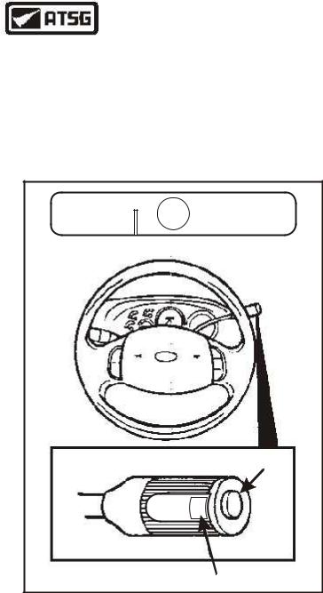
INSTRUMENT PANEL RANGE SELECTOR INDICATOR
Vehicles equipped with the 5R55W/S series transmissions have a Transmission Control Switch (TCS) and a Transmission Control Indicator Lamp (TCIL), as shown in Figure 5. The shift quadrant has the following positions P, R, D, 3, 2 and 1, as shown in Figure 5.
P R N D 3 2 1
INSTRUMENT PANEL RANGE SELECTOR INDICATOR
TCS
OVERDRIVE OFF
TCIL
Figure 5
MANUAL SHIFT SELECTOR
"P" = Park
When in the Park position, there is no power flow through the transmission and the parking pawl locks the output shaft to the case. The engine may be started and the key may be removed.
"R" = Reverse
When in the Reverse position, the vehicle may be operated in a rearward direction at a reduced gear ratio, and the back-up lamps are illuminated.
"N" = Neutral
When in the Neutral position, there is no power flow through the transmission, the output shaft is not held and is free to turn. The engine may be started and the key can not be removed.
"D" = Overdrive (TCS "OFF")
When in the D position, with the TCS switch "OFF", there will be automatic upshifts 1st through 5th gear, automatic downshifts 5th through 1st gear, and apply and release of the TCC depending on vehicle speed, throttle position and engine coolant temperature. This is the normal position for most forward driving and provides the maximum fuel economy during normal operation. This unit also has engine braking in 5th gear.
"D" = With TCS "ON"
When in the D4 position, with the TCS switch "ON", there will be automatic upshifts 1st through 4th gear, automatic downshifts 4th through 1st gear, and apply and release of the TCC depending on vehicle speed, throttle position and engine coolant temperature. This position may be selected for towing, or driving in hilly terrain. This unit also has engine braking in 4th gear.
"3" = 3rd Gear
This position provides a pull-in shift to 3rd gear with coast braking. After an automatic downshift, a 3rd gear hold occurs with coast braking. In this position 3rd gear starts occur.
"2" = 2nd Gear
This position provides a pull-in shift to 2nd gear with coast braking. After an automatic downshift, a 2nd gear hold occurs with coast braking. In this position 2nd gear starts occur.
"1" = 1st Gear
This position provides 1st gear operation only, and used for descending steep grades. If this position is selected at normal road speeds, the transmission will downshift to the next lower gear, and continue downshifting at safe pre-calibrated road speeds until it reaches 1st gear.
Copyright © 2004 ATSG
AUTOMATIC TRANSMISSION SERVICE GROUP |
9 |
|
Technical Service Information
|
|
|
|
|
|
CENTRAL JUNCTION BOX |
|
|||||||
CENTRAL JUNCTION BOX (UNDERDASH) |
|
|
|
|
|
|
||||||||
Transmission Related Fuses Only |
|
|
|
|
|
|
|
|
||||||
FUSE |
APPLICATION |
|
|
|
|
|
|
|
|
F-5 |
||||
F27 Digital Range Sensor (Reverse Lamps) (7.5A) |
|
|
|
|
|
F15 |
F-4 |
|||||||
F29 Digital Transmission Range Sensor (10A) |
|
|
|
|
|
|
F14 |
|||||||
|
|
|
|
|
|
F-3 |
||||||||
|
|
|
|
|
|
|
|
|
|
|
|
|
F13 |
|
|
|
|
|
|
|
|
|
|
|
|
|
|
F-2 |
|
|
|
|
|
|
|
|
|
|
|
|
|
|
F12 |
|
|
|
|
|
|
|
|
|
|
|
|
|
|
F-1 |
|
|
|
|
|
|
|
|
|
|
|
|
|
|
F11 |
|
Located Under Dash |
|
|
|
|
|
|
|
|
|
|
||||
|
|
|
|
|
F30 |
|
F25 |
F20 |
F10 |
|
||||
Panel, Driver Side |
|
|
|
|
|
|
|
|||||||
|
|
|
|
|
F29 |
|
F24 |
F19 |
F-9 |
CENTRAL |
||||
|
|
|
|
|
|
|
|
|
|
|||||
|
|
|
|
|
|
|
|
|
F28 |
|
F23 |
F18 |
F-8 |
JUNCTION BOX |
|
|
|
|
|
|
|
|
|
|
|
||||
|
|
|
|
|
|
|
|
|
F27 |
|
F22 |
F17 |
F-7 |
|
|
|
|
|
|
|
|
|
|
F26 |
|
F21 |
F16 |
F-6 |
|
|
|
|
|
|
|
BATTERY JUNCTION BOX |
|
|||||||
Battery |
|
|
|
|
|
|
|
|
|
|
|
BATTERY JUNCTION BOX (UNDERHOOD) |
||
Junction Box |
|
|
|
|
|
|
|
|
|
|
||||
|
|
|
|
|
|
|
|
|
|
|
Transmission Related Fuses Only |
|||
|
|
|
|
|
|
|
|
|
|
|
|
|
||
|
|
|
|
|
|
|
|
|
|
|
|
FUSE |
|
APPLICATION |
|
|
|
|
|
|
|
|
|
|
|
|
F11 PCM Power Relay (40A) |
||
|
|
|
|
|
|
|
|
|
|
|
|
F12 |
Starter/Ignition Relay (50A) |
|
|
|
|
|
|
|
|
|
|
|
|
|
F15 Powertrain Control Module PCM (15A) |
||
|
|
|
|
|
|
|
|
|
|
|
|
F17 4WD Control Module (20A) |
||
|
|
|
|
|
|
|
|
|
|
|
|
F18 4WD Control Module (20A) |
||
|
|
RO |
N |
T |
|
|
|
|
|
|
|
F37 A/C Relay, Trans Solenoid Body (Term 3) (15A) |
||
|
|
|
|
|
|
|
|
|
F40 |
Powertrain Control Module, MAF, Cruise (15A) |
||||
|
|
|
|
|
|
|
|
|
|
|||||
|
F |
|
|
|
|
|
|
|
|
|
F41 |
PCM Power Relay, PCM Power Diode (15A) |
||
|
|
|
|
|
|
|
|
|
|
|
|
|||
|
F-1 |
F-2 |
|
|
F-4 |
F-5 |
F-6 |
F-7 |
|
|
|
|
|
|
|
|
|
|
|
|
|
|
|
|
|
|
|
|
Ignition |
|
|
|
|
|
|
|
|
|
|
|
|
|
|
Relay |
|
F-9 |
F-10 |
F-11 |
F-12 |
F-13 |
-14 |
-15 |
-16 |
-17 |
-18 |
|
|
PCM |
|
|
|
|
Power |
|||||||||||
BATTERY |
|
|
|
|
|
F |
F |
F |
F |
F |
|
|
Diode |
|
|
|
|
|
|
|
|
|
|
|
|
|
|||
JUNCTION BOX |
|
|
|
|
|
|
|
|
|
|
|
|
|
|
|
F-19 |
F-20 |
F-21 |
F-22 |
F-23 |
|
|
F-26 |
F-27 |
F-28 |
A/C Clut |
Starter |
|
|
|
|
|
Relay |
|
||||||||||
|
|
|
Relay |
|
||||||||||
|
|
|
|
|
|
|
|
|
|
|
|
|
|
|
F-29 |
F-30 |
|
F-33 |
F-34 |
|
F-36 |
|
F-42 |
|
|
|
|
||
|
|
|
F-43 |
|
|
|
|
|||||||
|
|
|
|
|
|
|
|
|
|
|
|
|
|
|
|
|
|
|
|
|
|
|
|
|
F-44 |
|
|
PCM |
Brake |
|
|
|
|
|
|
|
|
|
|
|
|
|
||
|
|
|
|
|
F-37 |
F-38 F-39 |
F-40 |
F-41 |
|
F-45 |
|
|
Power |
|
|
|
|
|
|
|
|
|
Pedal |
||||||
|
|
|
|
|
|
F-46 |
|
|
Relay |
|||||
|
|
|
|
|
|
|
|
|
|
|
|
|
Relay |
|
|
|
|
|
|
|
|
|
|
|
|
|
|
|
Copyright © 2004 ATSG |
Figure 6
10 |
AUTOMATIC TRANSMISSION SERVICE GROUP |
|