

5R55W
.pdfTechnical Service Information
Fo |
rd |
Line Pressure Tap |
(Pressure Control Solenoids "A" And "B") |
Copyright © 2004 ATSG |
|
|
|
A |
|
|
-D |
|
|
2P |
|
|
|
2L |
L-B |
|
|
|
61 |
|
|
RJ |
||
|
|
43 |
|
|
00 |
7 |
|
|
|
|
C1 |
|
|
-9 |
|
|
BD |
|
|
|
61 |
|
|
|
43 |
|
|
|
00 |
|
|
RJL |
-B |
|
|
|
|
|
|
Pressure Control Solenoid "C" |
|||
Pressure Tap |
|
|
|
Copyright © 2004 ATSG |
|||
Figure 17
LINE PRESSURE TEST
1.There are 3 Pressure Control solenoids located in the solenoid body, PC "A", PC "B", PC "C", used to control all application pressures.
2.Start engine and check line pressures using the chart provided below to determine if the line pressure is within specifications.
Figure 18
Special Note: The line pressure tap in Figure 17, is used to verify output pressure from PC "A" or from PC "B", by turning either one OFF while verifying pressure from the other solenoid.
The 2nd pressure tap in Figure 18, is used to verify pressure readings from PC "C" solenoid. Use the chart below for proper specifications.
|
|
Idle |
WOT |
Idle |
WOT |
|
Vehicle/Engine |
Range |
Line Pres. |
Line Pres. |
PC "C" Pres. |
PC "C" Pres. |
|
Explorer/Mountaineer, |
P/N |
90-120 psi |
|
0-15 psi |
|
|
4.0L Engine |
|
|
|
|
|
|
Reverse |
100-140 psi |
282-380 psi |
90-120 psi |
112-134 psi |
||
|
||||||
|
(D), 3, 2, 1 |
90-110 psi |
228-263 psi |
0-15 psi |
0-15 psi |
Explorer/Mountaineer, |
P/N |
90-120 psi |
|
0-15 psi |
|
|
4.6L Engine |
|
|
|
|
|
|
Reverse |
90-120 psi |
282-380 psi |
90-120 psi |
112-134 psi |
||
|
||||||
|
(D), 3, 2, 1 |
80-110 psi |
228-263 psi |
0-15 psi |
0-15 psi |
Figure 19
AUTOMATIC TRANSMISSION SERVICE GROUP |
21 |
|
Technical Service Information
FORD 5R55S/W
CHECKING FLUID LEVEL
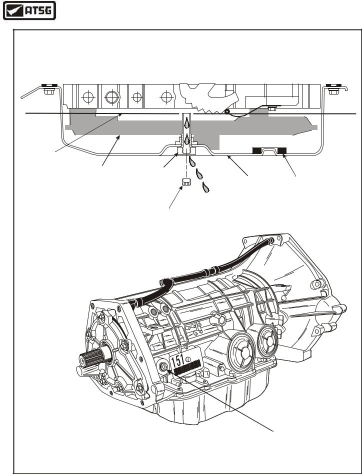
Checking the fluid level on any vehicle equipped with Ford Motor Companys new 5R55W/S transmission may become confusing to some technicians. There is a plug on the right rear of the transmission case, as shown in Figure 22, that would lead one to believe that this is where you check the fluid level, since some of the other manufacturers are currently checking fluid level in this manner.
However, this is a "Fill" plug only on the new 5R55W/S transmission from Ford Motor Company, which is currently found in the Explorer and Mountaineer vehicles. To "Check" for the correct fluid level, you must remove the check plug, which is located in the center of the bottom pan drain plug, and is removed with an allen wrench, as shown in Figure 22, while holding the drain plug with the proper size wrench so as not to loosen the drain plug.
We have provided you with a cut-away drawing of the bottom oil pan and the drain plug so that you will understand how this system works. Notice that the drain plug actually has a "stem" made on it that extends some distance up into the bottom pan, which is now our way to establish the proper fluid level in the transmission. By removing the "Check" plug from the "Drain" plug, the fluid should just trickle over the stem and out through the center of the drain plug, as shown in Figure 22. The "Fill" plug in the right rear of the case is your only way to replace and/or fill with fluid, in the 5R55W/S transmission.
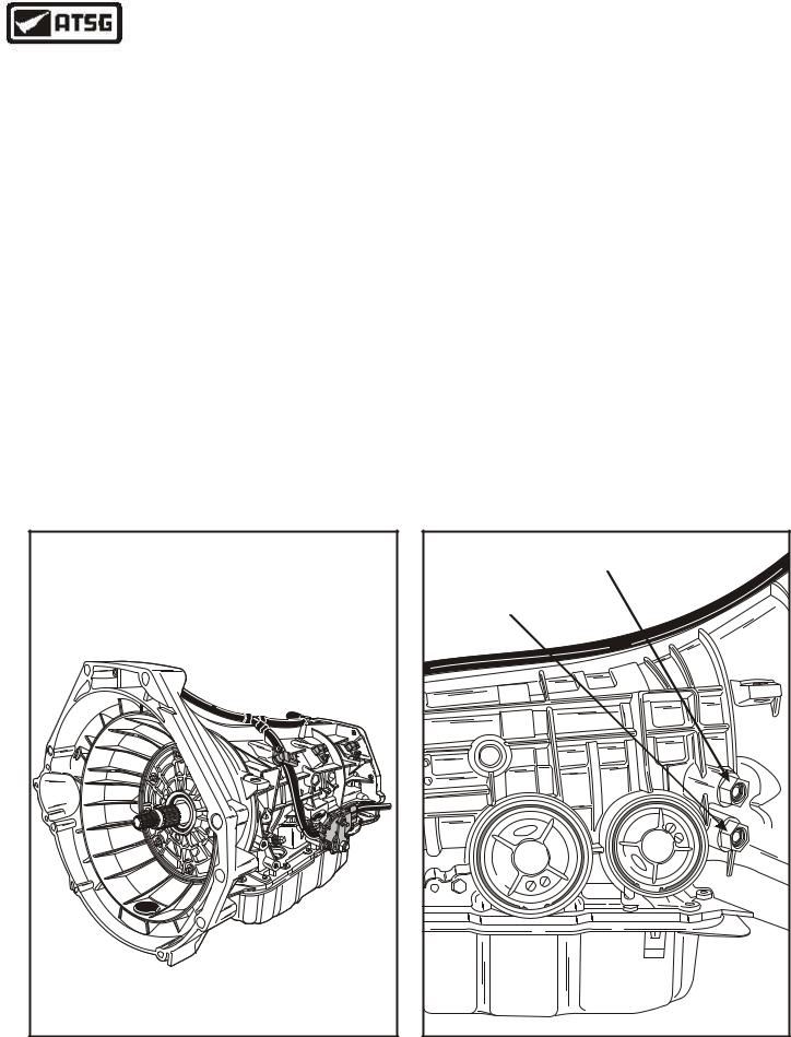
We have also identified the cooler line fittings and lines, as shown in Figure 21.
SPECIAL NOTE: |
|
THIS UNIT REQUIRES MERCON® V |
|
TRANSMISSION FLUID |
|
|
AA-392F7-P2L1 |
|
L |
1600 |
TRA |
NEU |
|
Copyright © 2004 ATSG |
|
Figure 20
|
|
"FROM COOLER" |
|||||
"TO COOLER" |
|
|
|
|
|||
|
|
|
|
|
|
R |
|
|
|
|
|
1 |
3 |
|
|
|
|
|
|
|
6 |
|
|
|
|
d |
|
9 |
|
5 |
|
|
|
|
A |
4 |
|
||
|
or |
|
0 |
|
|
||
|
F |
|
|
|
|
|
|
|
|
|
A |
|
|
|
|
|
|
8 |
T9 |
|
|
|
|
|
|
3 |
|
|
|
|
|
8 |
|
65 |
3 |
d |
|
|
G |
|
R |
|
|
||||
|
|
|
|
r |
|
|
|
A |
|
|
|
o |
|
||
|
|
|
F |
AS |
|||
D |
|
|
|
||||
|
|
|
|
|
|
||
|
|
|
|
|
|
|
|
|
|
|
|
Copyright © 2004 ATSG |
|||
Figure 21
22 |
AUTOMATIC TRANSMISSION SERVICE GROUP |
|
Technical Service Information
|
CHECKING FLUID LEVEL |
|
|||
Required Fluid |
|
|
|
|
|
Level In Pan |
Bottom Pan |
|
|
|
|
Bottom Pan |
|
|
|
|
|
Oil Filter |
Drain Plug |
|
|
Bottom Pan |
Bottom Pan |
|
|
|
|
|
Magnet |
|
Oil Level |
|
|
|
|
|
Check Plug |
|
|
|
|
|
|
|
- |
A |
|
|
|
2P |
|
|
|
|
|
2LD |
|
|
|
|
|
L-B |
61 |
|
|
|
|
RJ |
|
|
|
|
|
43 |
|
||
|
|
00 |
|
7 |
|
|
|
|
|
C1 |
|
|
|
|
-9 |
|
|
|
|
BD |
|
|
|
|
|
61 |
|
|
|
|
|
43 |
|
|
|
|
|
00 |
|
|
|
|
RJ |
L-B |
|
|
|
|
|
|
|
THIS IS A "FILL" PLUG ONLY |
|
|
|
|
|
|
Copyright © 2004 ATSG |
Figure 22
AUTOMATIC TRANSMISSION SERVICE GROUP |
23 |
|
Technical Service Information
Intermediate Shaft |
|
|
Speed Sensor |
|
Output Shaft |
|
|
Speed Sensor |
|
|
AA-392F7-P2L1 |
|
|
L |
|
1600 |
TRA |
|
NEU |
|
Turbine Shaft |
|
|
Speed Sensor |
|
Copyright © 2004 ATSG |
|
|
Figure 23
TRANSMISSION DISASSEMBLY
EXTERNAL COMPONENTS
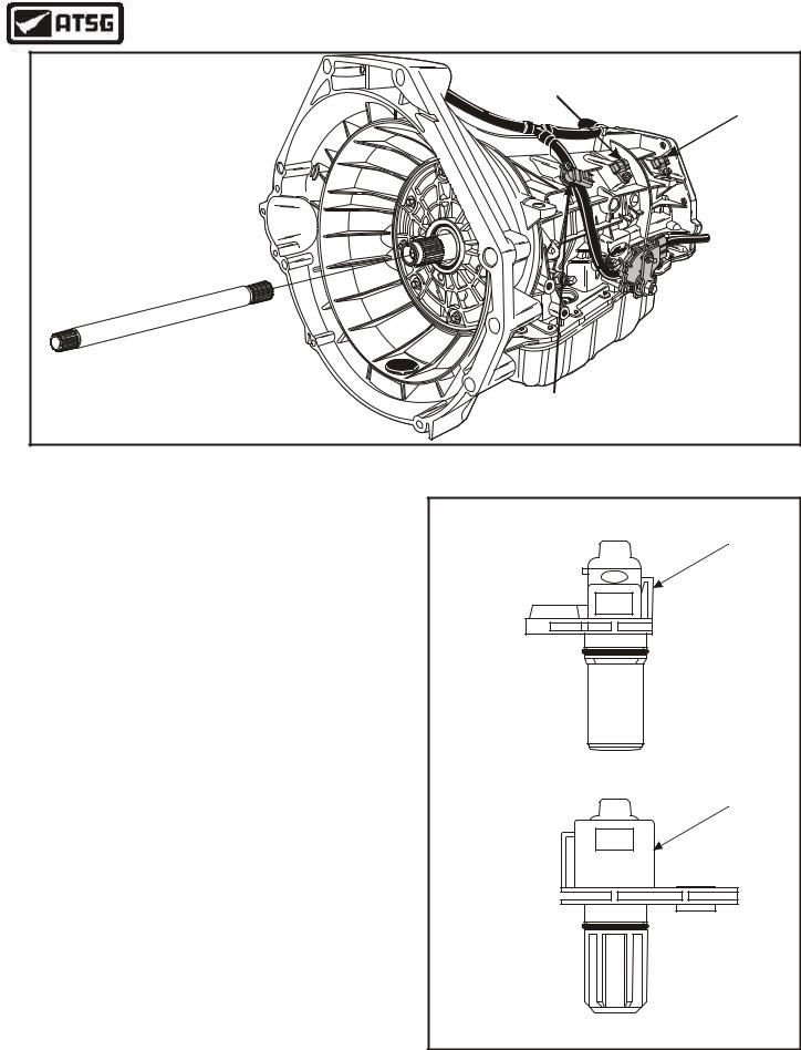
1.Remove the turbine shaft from the transmission as shown in Figure 23. Inspect the spline area on both ends and set aside for final assembly.
2.Remove the Turbine Shaft Sensor (TSS), the Intermediate Shaft Sensor (ISS) and the Output Shaft Sensor (OSS) from the transmission case, using a 30 Torx bit for the retaining bolts.
(See Figure 23).
3.The Turbine and Output sensors are exactly the same part number. Refer to Figure 24 for the differences between them, and the Intermediate shaft speed sensor.
4.Remove and discard the "O" ring seals from all three speed sensors, and use the chart found in Figure 13 to ohms check the sensors for proper resistance readings.
Turbine And Output
Shaft Speed Sensor
Ford
XW4P-7H 103 AA
Intermediate Shaft
Speed Sensor
XW4P-7M 103 AA
Continued on Page 25
Copyright © 2004 ATSG
Figure 24
24 |
AUTOMATIC TRANSMISSION SERVICE GROUP |
|
Technical Service Information
|
|
|
|
Manual |
|
|
|
|
Lever |
F |
or |
d |
|
Manual |
|
|
|||
|
|
|
||
|
|
|
|
|
|
|
|
|
Lever Nut |
|
|
|
|
Ford |
|
|
|
|
AA-392F721PL- |
|
|
|
|
AL |
|
|
|
1600 |
UTR |
|
|
|
NE |
|
|
|
|
|
|
Digital Transmission |
|
|
||
Range Sensor |
|
Retaining |
||
|
|
|
|
|
|
|
|
|
Bolts |
|
|
|
|
Copyright © 2004 ATSG |
Figure 25
EXTERNAL COMPONENTS (Cont'd)
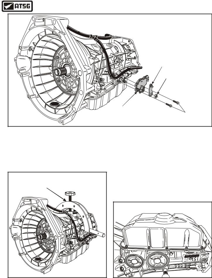
5.Remove the manual lever retaining nut and the manual lever, as shown in Figure 25.
6.Remove the two Digital Transmission Range sensor retaining bolts, as shown in Figure 25, and remove the sensor.
Universal Transmission |
|
|
Holding Fixture |
|
|
F |
or |
d |
|
||
|
|
|
Copyright © 2004 ATSG |
||
Figure 26
7.Install a compatible holding fixture onto the transmission case, as shown in Figure 26, that will allow you to rotate the transmission when installed in the bench fixture.
8.Install the transmission into the bench fixture and rotate, so that the bottom pan is facing up, as shown in Figure 27.
Continued on Page 26
|
|
|
6 |
|
|
|
2 |
|
|
|
- |
|
|
|
1 |
8 |
|
|
|
A |
F |
|
C |
G |
|
||
|
or |
|
A |
|
d |
6 |
|
|
R |
0 |
|
|
3 |
5 |
|
|
T 3 |
|
|
|
9 8 |
|
|
|
A |
|
|
|
6540 A |
|
F |
|
19 |
|
|
|
R3 |
|
dro |
|
|
|
Copyright © 2004 ATSG |
Figure 27
AUTOMATIC TRANSMISSION SERVICE GROUP |
25 |
|
Technical Service Information
EXTERNAL COMPONENTS (Cont'd)
9.Rotate the transmission so that the bottom pan is facing up, as shown in Figure 27.
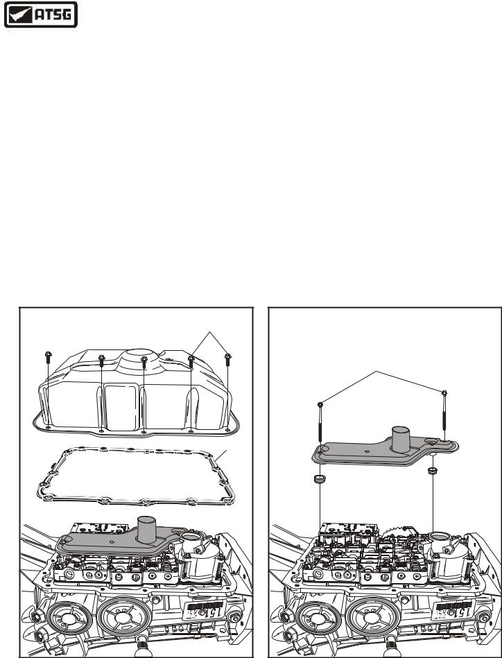
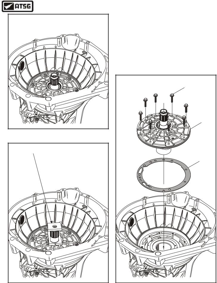
10.Remove the sixteen bottom pan bolts using an 8mm socket and remove oil pan, as shown in Figure 28.
11.Remove the bottom pan gasket from the case, as shown in Figure 28.
Note: The bottom pan gasket is reuseable. Clean and inspect the gasket for damage, and if it is not damaged, it may be re-used.
12.Remove the two filter retaining bolts, as shown in Figure 29, and remove and discard the oil filter and seals.
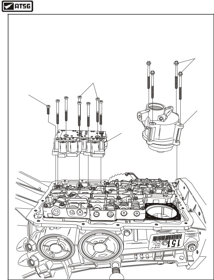
13.Remove the four rear servo retaining bolts and remove the Low/Reverse Servo assembly, as shown in Figure 30.
14.Set the Low/Reverse Servo assembly aside for the component rebuild process.
15.Remove the eight solenoid body retaining bolts using a 30 Torx bit, as shown in Figure 30.
16.Remove the solenoid body assembly from the transmission, as shown in Figure 30, and set aside for testing in component rebuild.
Continued on Page 28
|
|
|
PAN BOLTS |
|
|
|
(16 REQUIRED) |
|
|
|
PAN GASKET |
|
|
|
6 |
|
|
|
2 |
|
|
|
- |
|
|
|
1 |
8 |
|
|
|
A |
F |
|
C |
G |
|
||
|
or |
|
A |
|
d |
6 |
|
|
R |
0 |
|
|
3 |
5 |
|
|
T9 |
3 |
|
|
8 |
|
|
|
A |
|
|
|
6540 A |
|
F |
|
19 |
|
|
|
R3 |
|
dro |
|
|
|
Copyright © 2004 ATSG |
Figure 28
|
OIL FILTER |
||
|
RETAINING BOLTS |
||
|
(82mm LENGTH) |
||
|
|
|
6 |
|
|
|
2 |
|
|
|
- |
|
|
|
1 |
8 |
|
|
|
A |
F |
|
|
G |
|
CA |
|
|
or |
|
|
|
d |
6 |
|
|
R |
0 |
|
|
3 |
5 |
|
|
T 3 |
|
|
|
9 8 |
|
|
|
A |
|
|
|
6540 A |
|
F |
|
19 |
|
|
|
R3 |
|
dro |
|
|
|
Copyright © 2004 ATSG |
Figure 29
26 |
AUTOMATIC TRANSMISSION SERVICE GROUP |
|
Technical Service Information
|
|
|
|
|
|
|
LOW/REVERSE SERVO |
|
|
|
|
|
|
|
RETAINING BOLTS |
|
|
|
|
|
|
|
(70mm LENGTH) |
|
|
|
|
SOLENOID BODY |
|
||
|
|
|
|
RETAINING BOLTS |
|
||
|
|
|
|
(63mm LENGTH) |
|
||
SOLENOID BODY |
|
|
|
|
|
|
|
RETAINING BOLT |
|
|
|
|
|
|
|
(25mm LENGTH) |
|
|
|
|
|
|
|
|
|
|
|
|
|
|
LOW/REVERSE |
|
|
|
|
|
|
|
SERVO ASSEMBLY |
|
|
|
|
|
|
|
SOLENOID BODY |
|
|
|
|
|
|
|
ASSEMBLY |
|
|
|
|
|
|
|
6 |
|
|
|
|
|
|
|
2 |
|
|
|
|
|
|
|
- |
|
|
|
|
|
|
|
1 |
8 |
|
|
|
|
|
|
|
A |
|
|
|
|
|
|
|
G |
F |
|
|
|
|
C |
|
|
|
|
|
|
|||
|
|
or |
|
|
|
A |
|
|
|
|
d |
R |
6 |
|
0 |
|
|
|
|
3 |
538 |
|
|
|
|
|
|
T9 |
|
|
|
|
|
0 |
|
A |
|
|
|
|
4 |
A |
|
|
|
|
|
|
5 |
|
|
|
|
|
|
|
6 |
9 |
|
|
F |
|
|
|
|
1 |
|
|
|
|
|
|
3 |
|
|
o |
|
||
|
R |
|
|
|
dr |
|
|
|
|
|
|
|
|
|
Copyright © 2004 ATSG |
Figure 30
AUTOMATIC TRANSMISSION SERVICE GROUP |
27 |
|
Technical Service Information
EXTERNAL COMPONENTS (Cont'd)
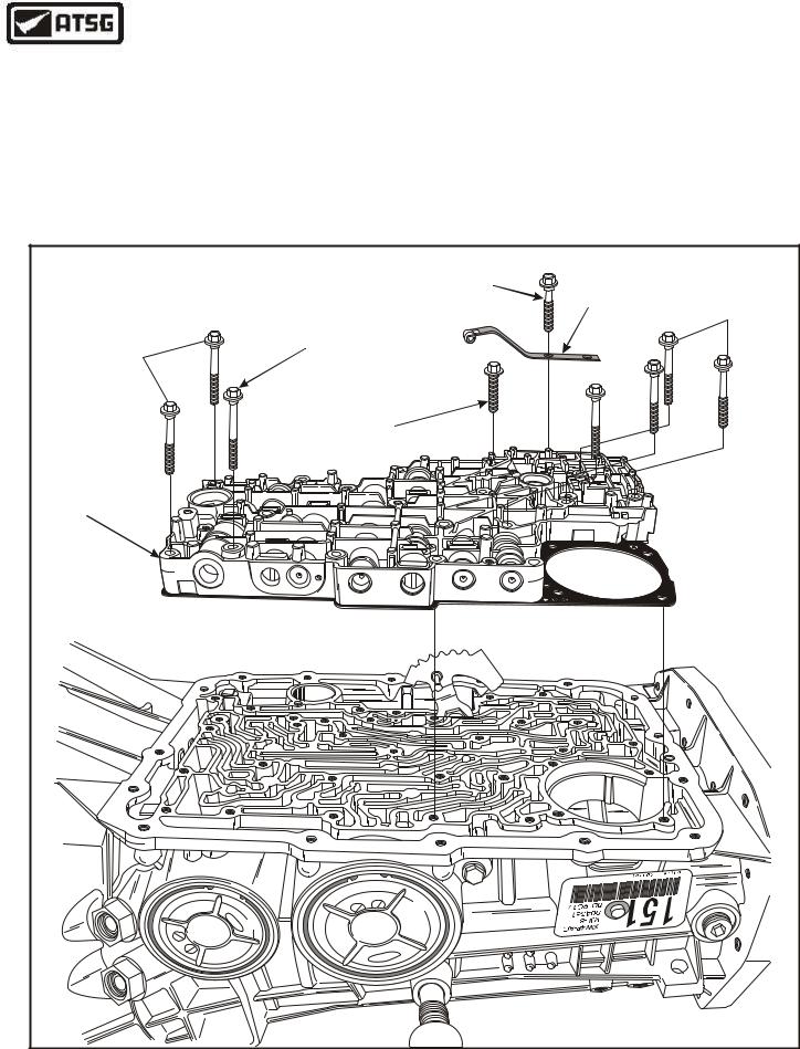
17.Remove the detent spring retaining bolt and the detent spring, as shown in Figure 31.
Note: This is the only valve body retaining bolt that is 30mm in length.
18.Remove the only 45mm in length valve body bolt, as shown in Figure 31, and note location.
19.Remove the only 27mm in length valve body bolt, as shown in Figure 31, and note location.
20.Remove the remaining 18 valve body retaining bolts as shown in Figure 31, and they are all 40mm in length.
21.Remove valve body and spacer plate assembly, as shown in Figure 31, and set aside for the component rebuild section.
|
|
|
|
|
|
|
DETENT SPRING BOLT |
|
VALVE BODY |
|
|
|
|
|
|
|
"1" REQUIRED |
DETENT |
RETAINING BOLTS |
|
|
|
|
VALVE BODY |
|
(30mm LENGTH) |
SPRING |
"18" REQUIRED |
|
VALVE BODY |
|
|
|
RETAINING BOLT |
|
|
|
(40mm LENGTH) |
|
|
|
|
"1" REQUIRED |
|
|
|
|
||
RETAINING BOLTS |
|
|
|
(45mm LENGTH) |
|
|
|
|
|
"18" REQUIRED |
|
|
|
|
|
|
|
|
|
(40mm LENGTH) |
|
|
|
|
|
|
|
|
|
|
|
|
|
VALVE BODY |
|
|
|
|
|
|
|
|
|
RETAINING BOLT |
|
|
|
||
|
|
|
|
(27mm LENGTH) |
|
|
|
||
VALVE BODY AND |
|
|
|
|
|
|
|
|
|
SPACER PLATE |
|
|
|
|
|
|
|
|
|
ASSEMBLY |
|
|
|
|
|
|
|
|
|
|
|
|
|
|
|
|
|
|
62 |
|
|
|
|
|
|
|
|
|
- |
|
|
|
|
|
|
|
|
|
1 |
8 |
|
|
|
|
|
|
|
|
|
A |
|
|
|
|
|
|
|
|
|
G |
F |
|
|
|
|
CA |
|
|
|
|
|
|
|
|
|
|
|||
|
|
or |
|
|
|
|
|
||
|
|
|
d |
R3 |
6 |
|
0 |
|
|
|
|
|
|
53 |
|
|
|
|
|
|
|
|
|
T9 |
8 |
|
|
|
|
|
|
|
|
|
|
|
|
|
|
|
|
0 |
|
A |
|
|
|
|
|
|
4 |
A |
|
|
|
|
|
|
|
|
5 |
|
|
|
|
|
|
|
|
|
6 |
9 |
|
|
F |
|
|
||
|
|
1 |
|
|
|
|
|
||
|
3 |
|
|
o |
|
|
|
||
|
R |
|
|
|
dr |
|
|
|
|
|
|
|
|
|
|
|
|
|
Copyright © 2004 ATSG |
Figure 31
28 |
AUTOMATIC TRANSMISSION SERVICE GROUP |
|
Technical Service Information
Caution: |
|
|
|
|
|
|
Loosen, but "Do Not" |
|
|
|
|
||
yet remove center |
|
|
|
|
||
support bolt. |
|
|
|
|
||
|
|
|
|
|
|
6 |
|
|
|
|
|
|
2 |
|
|
|
|
|
|
- |
|
|
|
|
|
|
1 |
8 |
|
|
|
|
|
|
A |
|
|
|
|
|
|
G |
F |
|
|
|
CA |
|
|
|
o |
|
|
|
|
|
|
r |
|
|
|
|
|
|
d |
R |
6538 |
|
0 |
|
|
|
3 |
|
|
|
|
|
|
T9 |
|
|
|
|
0 |
A |
|
|
|
|
|
4 |
A |
|
|
|
|
|
5 |
|
|
|
|
|
|
6 |
9 |
|
|
|
F |
|
1 |
|
|
|
||
|
3 |
|
|
|
o |
|
|
R |
|
|
|
dr |
|
|
|
|
|
|
|
Copyright © 2004 ATSG |
Figure 32
EXTERNAL COMPONENTS (Cont'd)
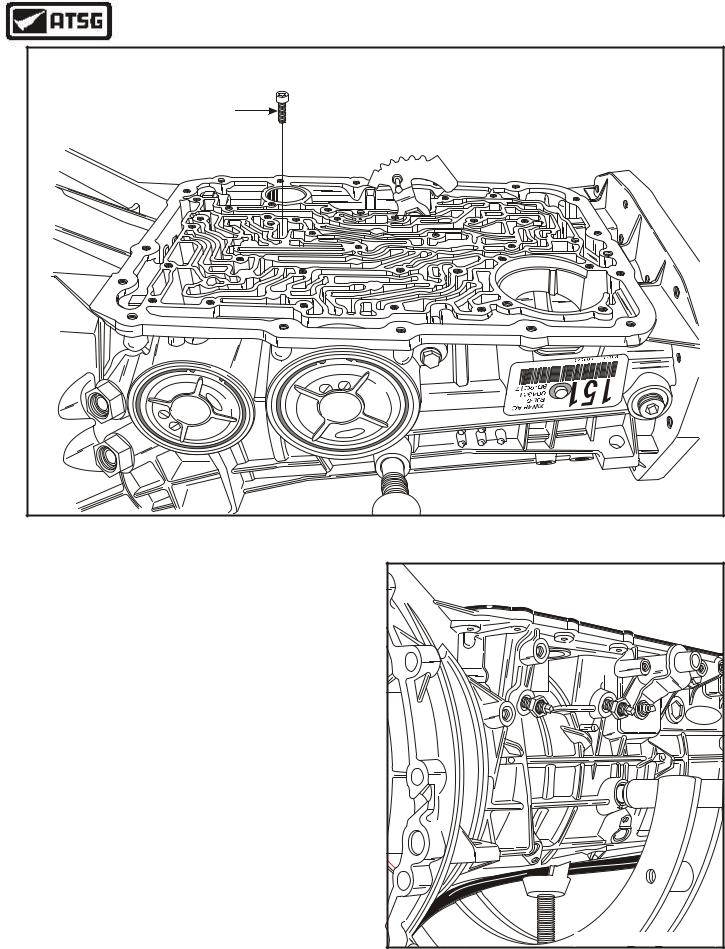
22.Loosen, but do not remove, the center support retaining bolt (See Figure 32).
23.Loosen both band adjusting screws, as shown in Figure 33.
24.Caution: Failure to loosen OD band adjusting screw prior to pump removal may cause damage to the pump or OD band.
25.Remove and discard the locknuts from the band adjusting screws, as they are not reusable.
Continued on Page 30
F |
dro |
Copyright © 2004 ATSG |
Figure 33
AUTOMATIC TRANSMISSION SERVICE GROUP |
29 |
|
Technical Service Information
Copyright © 2004 ATSG |
Figure 34
OIL PUMP REMOVAL TOOL TO |
BE USED WITH SLIDE HAMMER |
Copyright © 2004 ATSG |
INTERNAL COMPONENTS (Cont'd)
26.Rotate the transmission in bench fixture so that the pump is facing up, as shown in Figure 34.
27.Install the special pump puller, to be used with a slide hammer, as shown in Figure 35.
28.Remove the eight oil pump retaining bolts, as shown in Figure 36.
Note: Ford Motor Co. recommends that the pump bolts not be reused, but replaced.
Continued on Page 32
OIL PUMP ASSEMBLY |
RETAINING BOLTS |
(8 REQUIRED) |
OIL PUMP |
ASSEMBLY |
89 |
OIL PUMP |
TO CASE |
GASKET |
9 |
9 |
/ |
1 |
0 |
/ |
9 |
0 |
B |
A |
- |
9 |
6 |
6 |
L |
7 |
P- |
4 |
W |
X |
Copyright © 2004 ATSG |
Figure 35 |
Figure 36 |
30 |
AUTOMATIC TRANSMISSION SERVICE GROUP |
|