

NPAC 2014 Proceedings_final
.pdf324 |
Innovations Applicable to the Arctic |
??
??
??
??
??
??
??
???????
??
??
??
??
??
??
?? ? ?
Flotation starts lifting the ice pieces
|
????? |
|
|
|
|
|
????? |
????? |
|
|
|
|
Bow |
|
|
|
|
|
||
|
|
|
|
|
|
|
????? |
|
|
|
|
|
form |
|
|
|
|
|
|
pushes |
????? |
|
|
|
|
|
ice |
|
|
|
|
|
|
down |
|
|
|
|
|
?? |
and |
|
????? ????? ????? |
????? |
|
|
breaks it |
|
|
?????????? |
|
|
|||
|
????? |
|
|
? |
|
|
|
|
|
|
|
in |
|
????? |
|
|
|
|
|
|
|
|
|
|
|
pieces |
|
|
|
|
|
|
|
?? ? ?
After the breaking ice oes follow the verticals
?Round-form
bow |
Streight verticals |
|
steven |
||
|
Ice Knife
hinders the
hull to raise on ice
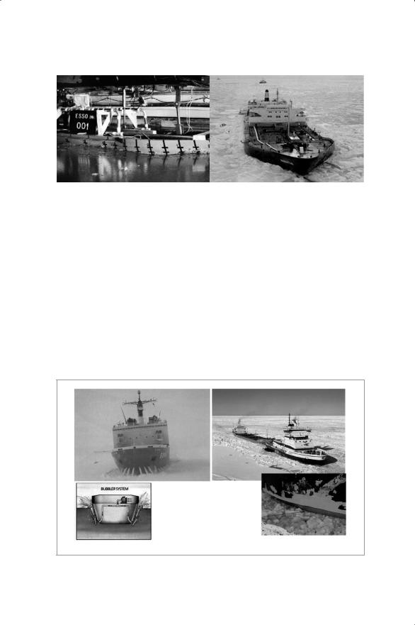
Figure IV-12. Icebreaking process and typical special features in an ice-operating vessel (top). Icebreaker Sampo from 1892 (bottom).
Commentaries |
325 |
|
|
|
|
|
|
|
Figure IV-13. Manhattan in thick ice
winterization and cold environment operations features.
The general development of ship machinery brought diesel-electric installations into icebreakers in the 1930s. Overall material development since the 1970s has allowed the use of direct diesel drives and geared propulsion installations, mainly with controllable pitch propellers, although fixed propellers in shaft lines remained the standard solution in lower ice classes. Russia started focusing on the application of nuclear power for icebreakers, especially for their remote Arctic destinations for which frequent refueling was not possible. The largest Yermak class diesel-electric icebreakers built in the early 1970s in Finland for Russia had close to 10,000-ton capacity for fuel, and yet suffered from limited endurance.
Waterfall |
Stainless |
and |
steel ice |
air bubbling |
belt |
Figure IV-14. Examples of typical additional features for friction reduction for ice-
going ships
326 |
Innovations Applicable to the Arctic |
The “Manhattan” project, a pioneering, full-scale trial initiated by Humble Oil (today ExxonMobil) in 1969 to bring North Slope (Prudhoe Bay) oil to the U.S. East Coast, was a leading effort for the related industries. With the side effect of creating the WIMB ice model test basin (today Aker Arctic) in Finland, the project opened up totally new tools for the related R&D efforts. The first new ships created on the basis of the ice model testing option, the sister icebreakers Urho and Atle, in 1974 for Finland and Sweden, thus adapted totally new hull forms and more efficient operability in ice. The physical fundamentals of icebreaking were learned simultaneously, and many additional features were innovated, such as air bubbling and solvent-free epoxy coatings as well as stainless steel ice belts, all for reduction of friction.
In this period, Canada opened up the Mackenzie Delta area for hydrocarbon exploration. The specifics of the Beaufort Sea conditions, especially the presence of multi-year ice, divided the ice technology world into two schools. The Canadian designers and operators emphasized–and still emphasize–the role of a strong bow detailed for ice ramming combined with the maximum bollard pull in protected (nozzled) large propellers. Friction reduction was achieved by waterfall outlets in the bow and along the side hull. Simplicity in hull form and shaft line arrangements were also emphasized and direct engine drives preferred, with flywheels providing some of the required ice features for propulsion.
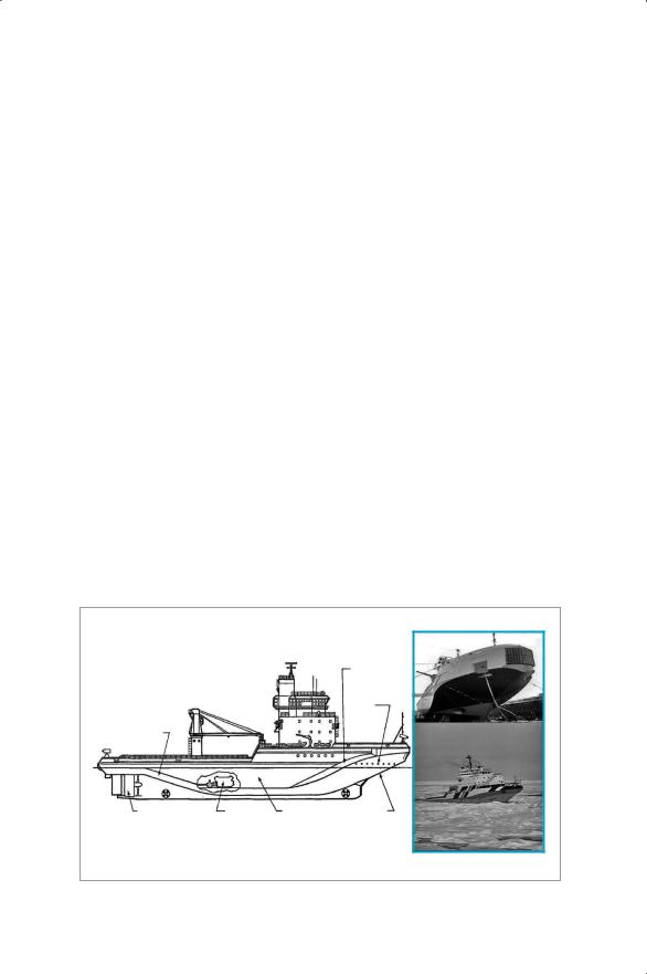
PRINCIPAL PARTICULARS
FEATURE |
MEASUREMENT |
|
|
|
LENGTH (OVERALL) |
90.0 |
m |
|
|
LENGTH (AT WATERLINE) |
84.2 |
m |
|
REAMER, WIDER |
BREADTH (MOULDED) |
17.25 m |
|
THAN MIDDLE BODY |
|
BREADTH (OVER REAMERS) |
19.25 m |
|
LUBRICATION HOLES |
|
|
|
|
|
|
DEPTH |
10.0 |
m |
|
FOR SPRAYING WATER |
DRAFT (MAXIMUM) |
8.5 |
m |
|
TO REDUCE HULL |
SHAFT POWER (HULL LUBE OFF) |
12.2 MW |
|
FRICTION |
|
|
|
|||
SHAFT POWER (HULL LUBE ON) |
11.8 MW |
|
|
|
UNDERCUT |
|
|
|
|
STERN |
|
|
|
|
SINGLE CP PROPELLER |
DIRECT DRIVE |
PARALLE? MIDDLE |
SPOON BOW |
|
IN NOZZLE |
AND DIESELS (2) |
BODY WITH |
FLAT STEM, |
|
|
1 GEARBOX |
|
VERTICAL SIDES |
SHARP SHOULDERS |
|
|
|
APPBOX. 80% OF |
|
|
|
|
SHELL PLATING FLAT |
|
|
|
|
HARD CHINES |
|
”Canmar Kigoriak”, today ”Talagi”
Figure IV-15. Typical Canadian icebreaker design from the 1980s

Commentaries |
327 |
The European school, mainly Finland and Germany, started focusing more on economics, fuel efficiency, and better operability and maneuverability. This thinking created ultimate hull forms like the Wärtsilä spoon bow and Thyssen Waas bow. The Ministry for Merchant Marine of the U.S.S.R., which already had operational experience from regular Arctic transports, was a keen client for each of these novelties, including the AC-AC drives made possible through technological innovations on frequency converters. A demonstration of these new features appeared (e.g., in the Baltic icebreaker Otso and the shallow-draught nuclear icebreaker Taymyr commissioned in 1991. The same technologies were adapted later in the 1990s in the USCG IB Healy built by the Avondale Shipyard with technology and model testing support from Aker Arctic of Finland. These developments were combined with the simultaneous introduction of icecapable electric pod drives, like the Azipod, and mechanical thrusters, like the Aquamaster.
The Canadian school built several offshore support icebreakers for Beaufort Sea oil companies (Dome Petroleum, Canmar, Beaudrill, Gulf Resources, etc.) with the ultimate example being the Swedish state icebreaker Oden, a frequent visitor to the North Pole and Antarctica.
LATEST DEVELOPMENTS
The introduction of the azimuthing thrusters for ice operation opened up also the possibility for a new mode of ship operation. Kvaerner MasaYard’s full-scale trials of the tanker Uikku in 1993-95 showed that ice resistance was reduced up to 50% and the ridge penetration capability significantly improved, although the original target for the R&D work was to achieve better maneuverability for icebreakers. This new energysaving “double acting” feature was soon adapted by several operators, both for icebreakers (e.g., the USCG IB Mackinaw, Norwegian Svalbard, and Finnish Botnica) as well as in independently operating cargo vessels (Norilsk Nickel’s Norilsk Nickel type six-vessel series, the 105,000 tdw tankers
Tempera and Mastera, Sovcomflot’s Mikhail Ulyanov and five Vasily Dinkov-type bow-loading 70,000 tdw shuttle tankers built in Korea). The last-mentioned tankers are operating the world’s first Arctic oil export shuttle service and have already transported more than 30 million tons of crude oil from Varandei to world markets.

328 |
Innovations Applicable to the Arctic |
|
|
|
|
|
|
|
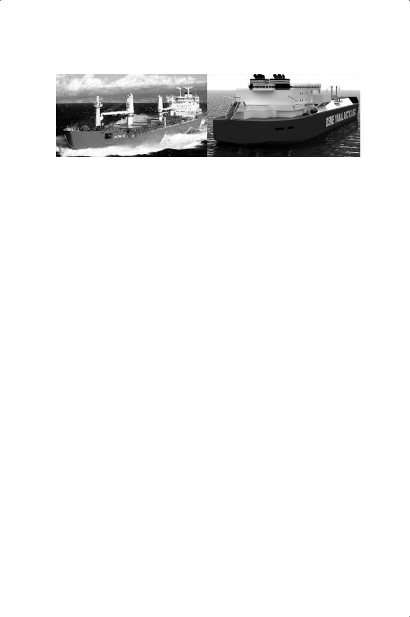
Note: New technology has enabled new logistic systems, allowing for new industrial production investments in the Arctic regions. On the left is the Aker Yards-built DAS™ vessel Norilsk Nickel in independent sternfirst ice operation in 1.5m-thick ice in the Kara Sea (photo: Aker Arctic), and the Samsung-built 70,000 tdw Arctic shuttle DAS™ tanker Vasily Dinkov approaching the loading tower in Varandei (photo: Sovcomflot).
Figure IV-16. Aker Yards-built DAS™ vessel Norilsk Nickel (left) and Samsung-built 70,000 tdw Arctic shuttle DAS™ tanker Vasily Dinkov (right)
ABB, having taking over the Azipod business, soon got orders for new offshore support icebreaker installations, especially for the Caspian Sea and waters off Sakhalin. The “double-acting” ice operating mode was soon adapted also for mechanical Aquamaster, Steerprop, Schottel and Wärtsilä thrusters, so that today one can say that the azimuthing thruster is a standard solution in modern icebreaking vessels. The recent launch of the gas-fueled Canadian ferry F.A.Gauthier for STQ now brings to the market Steerprop’s IASuper ice class further developed contra-rotating (CRP) azimuthing thrusters.
The diesel-electric type of propulsion is well-suited for reduced emissions in ice, and most recently the latest stern-first operating new ships have additionally been fitted for the use of LNG fuel. This is the case for the latest state icebreaker for Finland and the 10 Arctic 172.000 m³ Arc 7 ice class LNG carriers contracted so far for the Yamal LNG project, which simultaneously establishes the first regular transit traffic on the NSR from the Kara Sea to the Pacific Ocean. Three of the carriers are jointly contracted by Mitsui O.S.K. Lines with the China Shipping (Group) Company, and six by Teekay LNG Partners L.P. through a new 50/50 joint venture with China LNG Shipping (Holdings) Limited, with completion from 2018 to 2020. The expected unit cost is 314 million USD, compared to some 200 million USD for similar standard carriers. The planned fleet, totalling 16 vessels, is being built by DSME of Korea.
Compatriot SHI has simultaneously signed contracts for smaller Arctic 40,000 tdw twin Arc 8 ice class Azipod DAS™-type crude oil shuttle tankers that will enter service in 2016.
Commentaries |
329 |
|
|
|
|
|
|
|
Note: The JMU-built Arctic bulk carrier MS Nunavik (photo: JMU) and an impression of the Yamal LNG Arctic LNG DAS™ carriers now under construction by DSME (photo: DSME).
Figure IV-17. The latest Arctic cargo vessels
Earlier ths year Fednav in Canada took delivery from JMU, Japan of the 25,000 tdw Arctic bulk carrier Nunavik for year-round operation for Glencore Xtrata’s nickel mine from the Hudson Strait Deception Bay to Quebec. She is an improved sister to Fednav’s Umiak I that operates from Labrador’s Voisey’s Bay. These vessels represent the Canadian design philosophy of strong bows combined with direct shaft line propulsion in protected nozzles. Waterfalls are provided for auxiliary service in the bow part. The MAN-B&W 21,770 kW slow-speed single diesel is adapted for 1.5m-thick ice operation through newly developed electronic control. The Nunavik is now preparing for a commercial voyage through the North West Passage from Northern Canada to China.
The above examples are clear evidence of better solutions introduced to industrial investors to provide improved economies by independent vessel operation in ice. New technology thus clearly enables new industrial investments in the North through improved logistics.
PROSPECTS AND CHALLENGES FOR THE FUTURE
World shipping is conservative, and it always takes a lot of time for technology improvements to be adopted by the shipping community. It has been encouraging, however, to learn that Russia’s shipping industry is keen on new developments and solutions, especially for ice operations, in which the nation and crews have long experience. Still, the lead times for implementing new technology introductions have typically been more than 10 years (e.g., the Sakhalin OSV’s and the Arctic DAS™ shuttle tankers), which is half the relevant patents’ validity time. Only in 2013, some 20

330 |
Innovations Applicable to the Arctic |
years after the prototype, the first Azipod installation was accepted into a Canadian project in the CCG IB John G. Diefenbaker to be completed in 2020.
In world shipping, two major factors affect future solutions: there is a general drive toward improved energy efficiency and lower emissions. The IMO has already issued the EEDI system to enhance the shipping industry’s involvement in the Kyoto process and countermeasures against increases of C02 emissions. An exemption for ice-going ships, which typically require more power and burn more fuel, has been issued for vessels that are able to penetrate ice thicker than 1.0m. In certain “ECA” areas, additional emission limitations have been introduced on NOx and SOx. The Arctic Council has established a task force to consider regulations on black carbon, especially for the Arctic trades. One solution has been to use alternative fuels like LNG. But in general, Arctic industries need to seek further, innovative technologies to reach the general industry goals. Today, underwater radiated noise is also considered a kind of emission likely to affect marine mammals.
Environmental movements have recently generated additional challenges, especially for oil drilling-related activities. This has been experienced especially by Shell Alaska, whose drilling campaign in the Chukchi Sea has already been delayed for more than seven years from the original plans. Great emphasis has been put on oil spill combat preparedness, and full mobilization of the necessary support fleet and readiness for drilling a relief well in the same season appear to have become standard requirements that are also reflected in the ExxonMobil/Rosneft drilling campaign of August 2014 in the Kara Sea.
Further challenges to development are arising from the general concern about the safety of Arctic shipping and operations, which have been addressed in the Arctic Council’s Arctic Marine Shipping Report for example. This concern for sufficient risk mitigation has now been responded to by IMO, which is in an advanced stage of launching the Polar Code. This code will set common safety standards for all Arctic and Antarctic operations from 2017 onward and additionally provide each vessel with a Polar Operations Manual that will describe the vessel’s real ice capability for the intended tasks in specific areas. The code is expected to change many practices adopted by various flag states so far, and with the new environmental regulations will indirectly affect vessel designs.

Commentaries |
331 |
Commentary
Toshiyuki Kano and Takahiro Majima
First of all, thanks to Mike Aumond and Kuk Jin Kang for their papers on “A Fiber Optic System for Canada’s Western Arctic” and “Introduction to the KRISO Ice Tank.” They discuss issues of innovations applicable to the Arctic from two distinct points of view.
Last year, we focused on greenhouse gas emissions on the Northern Sea Route (NSR), the energy efficiency of ice class ships, and monitoring navigation systems and introduced a comparison of the Suez Canal Route (SCR) and the NSR in terms of environmental impact. This time, we’d like to introduce results focused on each route from an economic perspective, and make some comments on the two presentations.
Specifically, we would like to comment on the following points:
•Shipping cost estimations for the NSR considering ship performance in ice,
•Expectations for the KRISO ice tank,
•Expectations for the information infrastructure of the Arctic
To begin, we will introduce a simulation study of cost estimates for the NSR considering ship performance in ice. Then, we will comment on the presentations related to our study.
SHIPPING COST ESTIMATES
Objectives
The NSR has distance and time advantages compared to the traditional SCR with regard to shipments between Northeast Asia and Northwest Europe. Considering greenhouse gas emissions on a global level, a significant GHG reduction could be expected by using the NSR. However, larger engine output is required, and GHG emissions increase when navigating in ice. The comparative advantages of the NSR and SCR should be evaluated not only from the perspective of distance and time savings, but

332 |
Innovations Applicable to the Arctic |
also from an environmental conservation perspective (Kano et al., 2013). It is necessary to meet technical innovation challenges for ice-class vessels. Iceclass vessel energy efficiency should be improved (Kano et alet al., (2013). Here, we introduce a simulation study of cost evaluation of shipping via the NSR and the SCR.
Background
Many related studies have been conducted for a comparative analysis of the estimated shipping cost through the NSR and the SCR. Since the assumptions regarding cost estimates vary among the studies, however, there remain some difficulties in comparing the estimated shipping costs in the studies. Furuichi et al. (2012) tried to establish a common platform for a wide range of cost assumptions by clarifying and analyzing cost components, referring to the literature as well as the most recent interviews with NSR shipping professionals. They accomplished an empirical analysis and produced cost estimates for container transport between East Asia and Europe.
Furuichi et al. (2012) had calculated and analyzed specific shipping costs such as container ship price, annual shipping frequency, annual container throughput, depreciation costs, NSR fees, Suez Canal fees, crew costs, maintenance costs, insurance costs, fuel costs and annual port dues, assuming that the totals correspond to the annual shipping cost of container transport between Yokohama and Hamburg. The methodology for cost estimation was clear. However, the analysis did not take into account ship performance in ice, which has a high impact on shipping costs.
Shipping Cost Estimation on the NSR Considering Ship Performance in Ice
Therefore, our study has made an economic evaluation in accordance with Furuichi et al. (2013) considering ship performance in ice. Here we have considered ice thickness and rate of ice that covers the sea and assumed the same ship performance as Kano et al., 2013 and reviewed the calculation method again to analyze the transportation cost.
Furthermore, describing a simple case study of containerized transportation between East Asia (Yokohama, Japan) and Europe (Hamburg, Germany), in this case, using the NSR is 6,975 NM, and the

Commentaries |
333 |
SCR is 11,465 NM. The distance of the NSR is 40% shorter. The NSR has a draft restriction of 13 m at the Sannikov Strait, and the maximum ship size is approximately 50,000 DWT. Therefore, we set both an ice class container ship and conventional ship at 4,000 TEU (Figure IV-18). We will provide an example of the shipping cost that is calculation-based and analyzed. Moreover, we consider the effects in cases of improving the ship’s performance in icy waters.
Results
Here we simulated the shipping cost per TEU in two scenarios intended for a 4,000 TEU ice class container ship.
Scenario 1: An ice class container ship would use the NSR when available to navigate and the SCR when the NSR is unavailable.
Scenario 2: A conventional ship would navigate the SCR at all times of the year.
We simulated and calculated the shipping cost per TEU of a container
Typical 4000 TEU Class Container Ship
Due to Shallow Water at Sannikov Strait (13 m depth) Route: From Yokohama to Hamburg
Route |
NSR |
Suez Route |
|
|
|
Distance[NM] |
6,975 |
11,465 |
|
|
|
Capa. Limit. [TEU] |
4,000 |
4,000 |
|
|
|
Distance of NSR is 40% shorter
Operational Scenarios
Scenario 1: Operate NSR in available season & SCR in unavilable seasons
Scenario 2: Operate SCR in all seasons
Ref. Average on 56 Ships (3950-4049TEU)
Det [ton] |
58,000 |
d [m] |
12.9 |
LBP |
260 |
Power [Kw] |
38,800 |
Speed [Kt] |
23.8 |
NSR
SCR
Figure IV-18. Simulation study on NSR vs. SCR