


28 Lang et al
Recommendations. Because it is theoretically more accurate than the area-length method, the biplane disk summation technique, which incorporates fewer geometric assumptions, should be the preferred method to measure LA volume in clinical practice. The upper normal limit for 2D echocardiographic LA volume is 34 mL/m2 for both genders.
10. Right Atrial measurements
Less research and fewer clinical outcomes data are available on the quantification of RA size. Although the right atrium can be assessed from different views, quantification of RA size is most commonly performed from the apical four-chamber view (Table 12). The minor-axis dimension should be taken from a plane perpendicular to the long axis of the right atrium, extending from the lateral border of the right atrium to the interatrial septum. In contrast to the left atrium, RA size
appears to be gender dependent, but prior ASE guidelines did not have sufficient data to provide normative data by gender.1,71
Recent data obtained from three cohorts of >2,400 patients now
provide normal values of RA dimensions for men and
women.12,73,165
As with the left atrium, RA volumes are likely to be more robust and accurate for determination of RA size compared with linear dimensions. At the time of the prior guideline document, limited data were available for the determination of normative RA volumes. Because there are no standard orthogonal RA views to use for an apical biplane calculation, a single-view area-length and/or disk
summation techniques has been proposed for RA volume determination.150,153,165-167 Of note, normal RA volumes for men
are slightly larger than those for women, with indexing to BSA
failing to equalize values between genders for reasons that are not fully understood.150,165 Recommendations for RA volume
normative data are made from the two largest most contemporary data sets12,165 (Table 13). RA volumes are underestimated with 2D echocardiographic techniques compared with 3DE.164,165,168 RA
volumes in adult subjects appear to be smaller than LA volumes.12,150,153,165 This is because the RA volumes were obtained
using a single-plane method of disks, in contrast to the LA volumes, which were established using the biplane technique.
Recommendations. The recommended parameter to assess RA size is RA volume, calculated using single-plane area-length or disk summation techniques in a dedicated apical four-chamber view. The normal ranges for 2D echocardiographic RA volume are 25 6 7 mL/m2 in men and 21 6 6 mL/m2 in women.
IV. THE AORTIC ANNULUS AND AORTIC ROOT
Detailed knowledge and quantification of the aortic root and aortic valve morphology has become even more crucial with the increasing use of transcatheter aortic valve implantation (TAVI) and transcatheter aortic valve replacement (TAVR) procedures. This knowledge is critically important for preprocedural planning, intraprocedural guidance, and postprocedural assessment.
The aortic root extends from the basal attachments of the aortic valve leaflets within the LV outflow tract to their distal attachment at the tubular portion of the aorta (the sinotubular junction).169 The aortic root is a geometrically complex structure that includes (1) the aortic valve annulus, (2) the interleaflet triangles, (3) the semilunar
Journal of the American Society of Echocardiography
January 2015
aortic leaflets and their attachments, (4) the aortic sinuses of Valsalva, and (5) the sinotubular junction.170-172 Aortic measurements should be made at the following sites: (1) the aortic valve annulus, (2) the maximal diameter of the sinuses of Valsalva,
(3) the sinotubular junction (usually a demarcated transition between the sinuses of Valsalva and the tubular portion of the ascending aorta), and (4) the maximal diameter of the proximal ascending aorta, including a notation of the distance between the measurement site and the sinotubular junction (Figure 10A).
11. The Aortic Annulus
The ‘‘aortic annulus’’ is not a true or distinct anatomic structure but is a virtual ring that may be defined by joining the basal attachments, or nadirs, of the three aortic leaflets. The distal (uppermost) attachments
of the leaflets, in the shape of a crown, form a true anatomic ring169,173 (Figure 10B). Approximately two-thirds of the circumfer-
ence of the lower part of the aortic root is attached to the muscular interventricular septum, while the remaining one-third is in fibrous continuity with the anterior mitral valve leaflet.174 Measurement of the aortic valve annulus before TAVI or TAVR is a challenge, and the ideal modality for its measurement has yet to be established.
During the initial TAVI and TAVR experience, aortic annular measurements were routinely performed using 2DE.174,175 Although the
standard approach during the early years of TAVI and TAVR was echocardiography using a one-dimensional measurement, this method has clear limitations for TAVI and TAVR valve sizing. At present, the two most commonly used imaging techniques used for measuring the aortic annulus before TAVI or TAVR are echocardiography and multidetector computed tomography (MDCT).
With echocardiography, measurements of the aortic annulus should be made in the zoom mode using standard electronic calipers in midsystole, when the annulus is slightly larger and rounder than in diastole, between the hinge points of the aortic valve leaflets (usually between the hinge point of the right coronary cusp and the edge of the sinus at the side of the commissures between the left coronary cusp and the noncoronary cusp) from inner edge to inner edge. All other aortic measurements should be made at end-diastole, in a strictly perpendicular plane to that of the long axis of the aorta. Aortic annular measurements may be difficult in patients with acoustic blooming caused by a calcified aortic annulus.176-179 As a general rule, calcium protuberances should be considered as part of the lumen, not of the aortic wall, and therefore excluded from the diameter measurement.
The anteroposterior diameter is commonly measured by both 2D TTE (from the parasternal long-axis view) and 3D TEE (from the longitudinal view of the proximal aortic root, usually 110 –130 ) and ap-
proximates the minor dimension of the annulus measured by MDCT.3,176,180 However, because the annulus is often elliptical,
with variable diameters, it is preferable to measure the annulus in a cross-sectional view, using 3D imaging, as recommended by the European Association of Echocardiography and ASE guidelines181; the American College of Cardiology Foundation, American Association for Thoracic Surgery, Society for Cardiac Angiography and Interventions, and Society of Thoracic Surgeons consensus document on TAVR182; the Society of Cardiovascular Computed Tomography expert consensus document on MDCT183; and others.184-187 Using 3D TEE, both the smaller (anteroposterior, sagittal) and larger (medial-lateral, coronal) diameters, as well as the perimeter and annular area, should be measured in a cross-sectional
Journal of the American Society of Echocardiography |
|
Lang et al 29 |
|
Volume 28 Number 1 |
|
|
|
|
|
||
Table 12 Recommendations for the echocardiographic assessment of RA size |
|
||
|
|
|
|
Parameter and method |
Echocardiographic imaging |
Advantages |
Limitations |
|
|
|
|
Linear dimensions. |
2D-guided linear measurements |
Easy to obtain |
Single dimension only |
The minor axis of the right atrium |
|
Established normal values |
Assumes that RA enlargement |
should be measured in the apical |
|
|
is symmetrical |
four-chamber view as the |
|
|
View dependent |
distance between the lateral RA |
|
|
|
wall and interatrial septum, at the |
|
|
|
midatrial level defined by half of RA long axis
Area. |
2D view |
More representative of actual |
Need of a dedicated view to |
Measured in the apical four- |
|
RA size than linear dimensions |
avoid RA foreshortening |
chamber view at end-systole, on |
|
Established normal values |
Assumes a symmetrical shape |
the frame just prior to tricuspid |
|
|
of the cavity |
valve opening, by tracing the RA |
|
|
View dependent |
blood-tissue interface, excluding |
|
|
|
the area under the tricuspid valve |
|
|
|
annulus. |
|
|
|
Volume. |
2D view |
More representative of actual |
Assumes a symmetrical shape |
2D volumetric measurements are |
|
RA size than linear dimensions |
of the cavity |
usually based on tracings of the |
|
|
Single plane volume calculation |
blood-tissue interface on the |
|
|
may be inaccurate since it as- |
apical four-chamber view. At the |
|
|
sumes that RA enlargement is |
tricuspid valve level, the contour is |
|
|
symmetrical |
closed by connecting the two |
|
|
Normal values not well estab- |
opposite sections of the tricuspid |
|
|
lished |
ring with a straight line. Volumes |
|
|
|
can be computed by using either |
|
|
|
the single plane area-length: |
|
|
|
"#
8 ðAÞ2
3p L
or the disks summation technique. 3D data sets are usually obtained from the apical approach using a full-volume acquisition
3D data sets |
No geometrical assumption |
Dependent on image quality |
|
||
|
Established normal values |
Lower temporal resolution |
|
|
Patient’s cooperation required |

30 Lang et al |
Journal of the American Society of Echocardiography |
|
January 2015 |
view in midsystole (Figure 11). It should be noted that the difference between major and minor diameters may be up to 6 mm.173,188-193
For a detailed, step-by-step approach to making these measurements using 3D TEE, which is beyond the scope of this document, the reader
is referred to four recent publications.184-187 By using these techniques, close agreement with MDCT can be achieved.184,185
It should be noted that proponents of each of the two modalities (3D TEE and MDCT) tout advantages. In fact, each of these methods has certain strengths and limitations. Limitations of MDCT include the need for contrast media, radiation exposure, inability to obtain real-time measurements during the procedure, and the need to control the heart rate for suitable gating. Threedimensional TEE also has limitations. First, the software required to use the methodology described by Kasel et al.184 and Pershad et al.185 is not currently available on all echocardiographic platforms. Second, visualization of the anterior portion of the annulus can be obscured by echo ‘‘dropout’’ due to annular calcification. In addition, calcification at the level of the annulus may hinder the ability to determine boundary definition and may make its shape irregular. Third, the plane formed by the nadirs of the three cusps is often not orthogonal to the LV outflow tract or aortic root; frequently the insertion of the right coronary cusp is inferior to that of the left and noncoronary cusps.183 Fourth, both the spatial and temporal resolution of 3D echocardiography is currently limited. Last, this
technique is operator dependent and may be difficult at times, even in experienced hands.173,174 Because of these potential
limitations, it is desirable to use a multimodality approach for aortic annular measurement.
12. The Aortic Root
With 2D TTE, the diameter of the aortic root (at the maximal diameter of the sinuses of Valsalva) should be obtained from the parasternal long-axis view, which depicts the aortic root and the proximal ascending aorta. This plane is slightly different from that of the long axis of the left ventricle (Figure 10A). Acquisition of this LV longaxis view may be performed from different intercostal spaces and at various distances from the left sternal border. Use of simultaneous biplane orthogonal images provided by matrix transducers may be helpful. The tubular ascending aorta is often not adequately visualized from a standard parasternal window. In these instances, moving the transducer closer to the sternum may allow visualization of a longer portion of the ascending aorta. In addition, the ascending aorta may sometimes be well visualized from right parasternal windows in the second or third intercostal space, especially when the aorta is dilated.
Measurements should be made in the view that depicts the maximum aortic diameter perpendicular to the long axis of the aorta. In patients with tricuspid aortic valves, the closure line of the leaflets (typically the right coronary cusp and the noncoronary cusp) is in the center of the aortic root lumen, and the closed leaflets are seen on the aortic side of a line connecting the hinge points of the two visualized leaflets. An asymmetric closure line, in which the tips of the closed leaflets are closer to one of the hinge points, is an indication that the cross-section is not encompassing the largest root diameter (Figure 12).
Unfortunately, there is no uniform method of measurement of the aortic root and aorta. Echocardiography uses the leading edge–to– leading edge (L-L) convention, but other techniques, such as MDCT and CMR, use the inner edge–to–inner edge (I-I) or outer edge–to–outer edge convention. In the consensus document,194 the ASE and EACVI writing committee took the initiative to provide
Table 13 Normal RA size obtained from 2D echocardiographic studies
|
Women |
Men |
||||
|
|
|
|
|
|
|
RA minor axis dimension (cm/m2) |
1.9 |
6 |
0.3 |
1.9 |
6 |
0.3 |
RA major axis dimension (cm/m2) |
2.5 |
6 |
0.3 |
2.4 |
6 |
0.3 |
2D echocardiographic RA volume (mL/m2) |
21 |
6 |
6 |
25 |
6 |
7 |
Data are expressed as mean 6 SD. |
|
|
|
|
|
|
Figure 10 (A) Sites for measurements of the aortic root and ascending aorta. This diagram illustrates the four sites at which measurements are recommended (light blue arrows): (1) the aortic valve annulus (hinge point of aortic leaflets), (2) the sinuses of Valsalva (maximal diameter, usually the midpoint), (3) the sinotubular junction, and (4) the proximal ascending aorta (the distance between the measurement site and the annular plane [purple arrowheads] should always be reported). The aortic annulus should be measured at peak systole, in contrast to the other dimensions, which are measured at end-diastole. The dashed lines, depicting the longitudinal axis of the left ventricle (LV) and that of the aortic root and proximal ascending aorta, are different. Note that the angle between these two axes varies from individual to individual and with age and pathology. (B) Normal anatomy of the aortic annulus. The aortic annulus accounts for the tightest part of the aortic root and is defined as a virtual ring (shaded) with three anatomic anchor points at the nadir of each of the attachments of the three aortic leaflets. Reproduced with permission from Kasel et al.184 Ao, Aorta; LA, left atrium.
a common standard for measurement of the aortic root and aorta by recommending a switch to the I-I convention for echocardiography. However, this goal of achieving uniformity among modalities was ultimately abandoned for several reasons. First, currently used longstanding reference values for the aorta were obtained using the L-L convention.195,196 Second, the L-L convention provides statistically
Journal of the American Society of Echocardiography |
Lang et al 31 |
Volume 28 Number 1 |
|
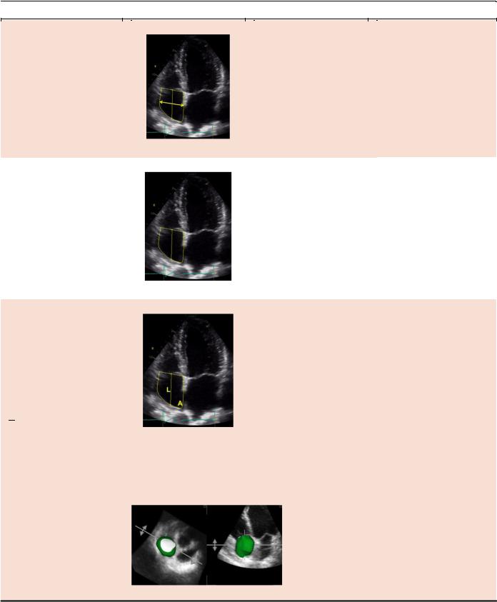
Figure 11 The smaller (antero-posterior, sagittal) aortic root diameter is measured using CT (A) or 3D TEE (C, zoomed cross sectional view) between the inner edges of the left (L) and non-coronary (NC) commissure to the opposite right (R) coronary sinus (A and C, yellow double arrows). The larger diameter (medial-lateral) is measured from the middle of the right sinus to the most distal point of the NC sinus (A and C, purple double arrows). Panel B shows zoomed cross-sectional CT views of aortic root at the sinus of Valsalva level using a double oblique image for orientation. Panel D shows a long-axis view of the aorta in obtained by multiplanar reconstruction. The red lines in (B) and (D) represent the planes from which the diameter of the aortic root should be measured at the level of the sinuses of Valsalva.
Figure 12 Correct (A) and incorrect (B, C) measurements of the aortic annulus (double arrows). (A) Centrally positioned diameter and central closure of leaflets. Thin lines correspond to the long axis of the ascending aorta and, orthogonally, to correct orientation of the annular diameter. (B) Incorrect, eccentric annular measurement. The hinge points are slightly displaced upward and do not correspond to the nadir of the cusp attachments, with incomplete opening and closing of leaflets. (C) Incorrect, oblique annular measurement. The annulus is ‘‘virtual’’ and only defined by the hinge-points of the three aortic valve leaflets. As such, much of the ring is without a visible anatomic structure. However, its location on any long-axis two-dimensional view can be approximated since the plane of the virtual annulus is approximately perpendicular to the long-axis of the aorta. When bisecting the maximum dimension of the annulus in the sagittal plane, one will image the right coronary cusp anteriorly and the fibrous trigone between the left and noncoronary cusps posteriorly. Because only one anatomic marker (the RCC hinge-point) is seen, the opposing annulus must be approximated with a measurement that is perpendicular to the long axis of the aorta. Attempting to measure what you believe to be 2 hinge-points (B and C) typically will measure within the sinuses of Valsalva and overestimate the annulus.
larger diameters than the I-I convention (by 2–4 mm), and switching to the I-I convention raised a concern that patients at potential risk for developing life-threatening complications such as aortic dissection and/or rupture would fall below a threshold for intervention recommendation by current guidelines. Accordingly, the aortic annulus should be measured using the I-I convention, but we continue to
recommend the L-L convention for measurements of the aortic root and aorta.
Two-dimensional echocardiographic aortic diameter measurements are preferable to M-mode measurements, because cardiac motion may result in changes in the position of the M-mode cursor relative to the maximum diameter of the sinuses of Valsalva. This