

mentor_instroduction
.pdfFoundation for Declaring Objects--Types
________________________________________________________________________________________________________________________
VARIABLE time_of_day : clock_time;
. . .
time_of_day.minute := 35; -- loads 35 into element "minute"
start_hour := time_of_day.hour; -- assigns value of element -- "hour" to "start_hour"
When assigning values to or reading from record elements, the types of the record elements must match the types of the variables; otherwise, an error occurs. You can also access a record as an aggregate, in which case all the elements are assigned at once, as shown in the following example:
VARIABLE time_of_day : clock_time;
. . .
time_of_day := (12, 05, 23, am);
File Types
This subsection introduces the concept of file types but does not go into specific details because it is beyond the scope of this manual. For more information on file types, refer to the Mentor Graphics VHDL Reference Manual.
File types allow you to declare external files that contain objects of the type you specify. External files refer to those that are external to the main hardware description model file. The following example shows the format of a file type definition:
file type definition .......... |
file of type_mark |
Access Types
This subsection introduces the concept of access types but does not go into specific details because it is beyond the scope of this manual. For more information on file types, refer to the Mentor Graphics VHDL Reference Manual.
Access types let you designate objects that are variable. The following example shows the format of an access type definition:
Mentor Graphics Introduction to VHDL, July 1994 |
3-13 |
Foundation for Declaring Objects--Types
________________________________________________________________________________________________________________________
access type definition ... |
access subtype_indication |
Retrieving Information on Certain Kinds of Objects
Once an object has been declared, you might want to retrieve some information from the object and use the result in an operation or test condition. VHDL provides a number of predefined attributes that can examine certain parameters of any one of the following kinds of objects:
●Arrays
●Blocks
●Signals (scalar or composite)
●Types (scalar, composite, or file)
This description of predefined attributes serves only as an overview. Refer to the Mentor Graphics VHDL Reference Manual for a complete discussion of all predefined attributes. The following is an example format of an attribute name, which is used with both user-defined and predefined attributes to denote a value, function, type, range, signal, or constant associated with a design entity:
attribute name ................... |
prefix’attribute_simple_name |
You use the apostrophe (’) character followed by an attribute identifier to designate a particular attribute. The prefix is the object name or function call that the attribute will check.
The following example uses a standard predefined attribute (’event) in the condition in line 10.
3-14 |
Mentor Graphics Introduction to VHDL, July 1994 |
Foundation for Declaring Objects--Types
________________________________________________________________________________________________________________________
1LIBRARY my_lib; USE my_lib.my_qsim_logic.ALL;
2ENTITY incomplete_counter IS
3PORT (clock, data: IN my_qsim_state;
4 |
q_out: INOUT my_qsim_state); |
5 |
END incomplete_counter ; |
6 |
|
7 |
|
8ARCHITECTURE behav OF incomplete_counter IS
9BEGIN
10q_out <= data WHEN clock’event AND clock = ’1’ ELSE
11 |
q_out; |
12 |
END behav; |
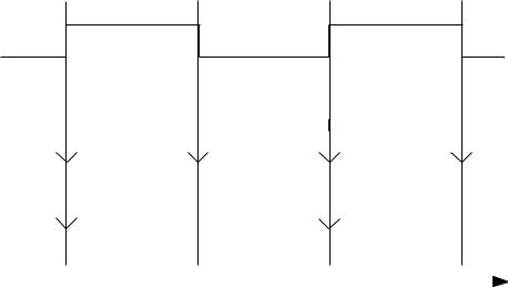
Attribute ’event (commonly pronounced "tic event") in line 10 is a signal attribute. The attribute checks the signal clock and returns a Boolean value of TRUE when there is an event on clock, or a value of FALSE if there is no event on clock. Figure 3-5 illustrates the returned values for clock’event in relation to the clock signal. Also shown in the figure is the returned values for the entire condition clock’event AND clock = ’1’. When the condition in line 10 of the previous code example is true, a rising clock pulse has occurred so the value of data is assigned to q_out.
clock
|
|
false |
true |
|
false |
true |
|
|
false |
true |
|
false |
true |
false |
|||||||||||||
clock’event |
|
|
|
|
|
|
|
|
|
|
|
|
|||||||||||||||
|
|
|
|
|
|
|
|
|
|
|
|
|
|
|
|
|
|
|
|
|
|
|
|
|
|
||
|
|
|
|
|
|
|
|
|
|
|
|
|
|
|
|
|
|
|
|
|
|
||||||
|
|
|
|
|
|
|
|
|
|
|
|
|
|
|
|
|
|
|
|
|
|
|
|||||
clock’event AND |
false |
true |
|
|
|
|
|
|
|
|
true |
|
false |
|
|
|
|
|
|||||||||
|
|
|
|
|
|
false |
|
|
|
|
|
|
|
|
|
|
|
|
|
||||||||
|
|
|
|
|
|
|
|
|
|
|
|
|
|
|
|||||||||||||
clock = ’1’ |
|
|
|
|
|
|
|
|
|
|
|
|
|
|
|
|
|
|
|
|
|
|
|
|
|
|
|
|
|
|
|
|
|
|
|
|
|
|
|
|
|
|
|
|
|
|
|
|
|
|
|
|
|
||
|
|
|
|
|
|
|
|
|
|
|
|
|
|
|
|
|
|
|
|
|
|
|
|
|
|
|
|
|
|
|
|
|
|
|
|
|
|
|
|
|
|
|
|
|
|
|
|
|
|
|
|
|
|
|
|
|
|
|
|
|
|
|
|
|
|
|
|
|
|
|
|
|
|
|
|
|
|
|
|
|
|
|
|
Figure 3-5. Signal Attribute Example
Mentor Graphics Introduction to VHDL, July 1994 |
3-15 |
Foundation for Declaring Objects--Types
________________________________________________________________________________________________________________________
The following example shows two predefined attributes, ’left and ’right, that operate on types. Type high_byte is declared in line 1 to have a range from 28 to 31. The bound values 28 and 31 are used in the loop parameter specification in line 3 by using the ’left and ’right attributes. Attribute ’left returns the high_byte bound value 28 and ’right returns the bound value 31.
1 TYPE high_byte IS RANGE 28 TO 31; 2
3FOR i IN high_byte’left TO high_byte’right LOOP
4--something happens
5END LOOP;
The previous example is used only to show the function of ’left and ’right. VHDL provides a more efficient method of extracting the range of type high_byte for a loop range as shown in the following code:
3 FOR i IN high_byte LOOP --The range is 28 to 31
The following example shows another predefined attribute, ’pos(x), that operates on a type. Attribute ’pos(x) returns an integer value that equals the position of the item that you define by supplying a parameter (x) to the attribute.
In line 1 of the following example, an enumerated type called opcode is declared. The opcode type contains nine instruction mnemonics. The comment in line 2 shows the positional location of each mnemonic. Line 4 declares constant stop to be an integer that is assigned a value related to the position of the corresponding halt (hlt) mnemonic. In other words, the result of opcode’pos(hlt) (which equals 8) is assigned to constant stop.
1 |
TYPE opcode IS (mov,lda,sta,jmp,ret,add,sub,nop,hlt); |
||||
2 |
--positions 0 1 2 |
3 |
4 5 6 |
7 |
8 |
3 |
|
|
|
|
|
4 |
CONSTANT Stop : integer := |
opcode’pos(hlt); |
-- stop = 8 |
||
The previous examples give you a basic look at predefined attributes and how you might use them in your hardware models. Refer to the Mentor Graphics VHDL Reference Manual for a complete description of all the predefined attributes and how to create user-defined attributes.
3-16 |
Mentor Graphics Introduction to VHDL, July 1994 |
Constructs for Decomposing Design Functionality
________________________________________________________________________________________________________________________
Section 4 Constructs for Decomposing Design Functionality
Many of the VHDL constructs have been previously introduced in the structural, behavioral, and data-flow descriptions. The examples used in those subsections solved relatively simple design problems.
This section identifies a number of VHDL constructs that allow the designer to decompose a complex design into smaller and more manageable modules. This subsection is divided into the following topics:
Concurrent Decomposition |
|
|
|
|
|
|
|
|
4-3 |
||||||
Block Statement |
|
|
|
|
|
|
|
|
|
|
4-4 |
||||
Component Instantiation |
|
|
|
|
|
|
|
|
|
4-7 |
|||||
Sequential Decomposition |
|
|
|
|
|
|
|
4-12 |
|||||||
Subprograms--Functions and Procedures |
|
|
|
|
4-13 |
||||||||||
Function Call |
|
|
|
|
|
|
|
4-24 |
|||||||
Procedure Call |
|
|
|
|
|
|
4-27 |
||||||||
Contrasting Concurrent and Sequential Modeling |
|
|
|
|
4-28 |
||||||||||
How Values Get Assigned to Signals and Variables |
|
|
|
4-36 |
|||||||||||
Resolving a Signal Value When Driven by Multiple Assignment |
|
|
|
||||||||||||
Statements |
|
|
|
|
4-43 |
||||||||||
Creating Shared Modules--Packages |
|
|
|
4-43 |
|||||||||||
Making a Package Visible--Library Clause and Use Clause |
|
|
4-48 |
||||||||||||
Mentor Graphics Introduction to VHDL, July 1994 |
4-1 |
Constructs for Decomposing Design Functionality
________________________________________________________________________________________________________________________
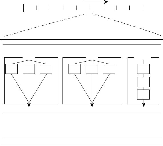
Consider the principles of concurrent and sequential operation as they relate to hardware simulation. Figure 4-1 shows the execution order for the VHDL statements in a hypothetical design during a given simulation timestep. The term timestep is used to denote the smallest time increment of a simulator. Time is shown at the top increasing from left to right, the same as in the trace window of a simulator (or on the screen of an oscilloscope).
TIME
1 |
2 |
3 |
4 |
5 |
6 |
7 |
8 |
9 |
Timestep 5
|
B1 |
|
|
B2 |
|
P1 |
Block |
|
|
Block |
|
Process |
|
CS1 |
CS2 |
CS3 |
CS1 |
CS2 |
CS3 |
SS1 |
|
|
|
|
|
|
SS2 |
|
|
|
|
|
|
SS3 |
Iteration 1 |
|
|
|
|
|
|
Iteration 2 |
|
|
|
|
|
|
CS = Concurrent Statement
SS = Sequential Statement
Figure 4-1. Concurrent and Sequential Operations
4-2 |
Mentor Graphics Introduction to VHDL, July 1994 |
Constructs for Decomposing Design Functionality
________________________________________________________________________________________________________________________
Most simulators run on systems with a single processor. With just one processor, concurrent processes are not actually evaluated in parallel on the simulator hardware. VHDL uses the concept of delta delay to keep track of processes that should occur in a given timestep but are actually evaluated in different machine cycles. A delta delay is a unit of time as far as the simulator hardware is concerned, but as far as the simulation is concerned, time has not advanced.
The processes in the two blocks (B1 and B2) and a process (P1) in Figure 4-1 are scheduled to execute (concurrently) within iteration 1 of timestep 5. The term iteration is used to denote a delta delay unit. (This example does not require a second iteration of timestep 5.)
Within blocks B1 and B2 are three concurrent statements that execute in parallel. Within process P1 are three sequential statements. Statement SS1 executes first, followed by SS2, and then SS3. Once all statements have finished execution, the simulator can advance to the next iteration or timestep. As far as the simulator is concerned, all of these operations (processes in B1 and B2, and P1) occur at the same time (during iteration 1 of timestep 5).
Concurrent Decomposition
This subsection identifies the constructs that define hardware functions that execute concurrently. The main focus of this subsection is to describe the following:
●The block statement, which is the primary concurrent statement used to decompose the hardware functionality into smaller modules
●The component instantiation statement, which defines the actual use of declared components
The following list identifies the VHDL statements that execute concurrently within a particular simulation timestep.
●Concurrent signal assignment statement (See Figures 2-21 and 2-22 on pages 2-31 and 2-33, respectively, for examples.)
Mentor Graphics Introduction to VHDL, July 1994 |
4-3 |
Constructs for Decomposing Design Functionality
________________________________________________________________________________________________________________________
●Process statement (See Figures 2-10 and 2-11 on pages 2-15 and 2-19, respectively, for examples.)
●Concurrent procedure call
●Concurrent assertion statement
●Block statement (used to group concurrent statements)
●Component instantiation statement
●Generate statement
Block Statement
The block statement allows you to group concurrent statements into one logical unit, which describes a portion of your design. Figure 4-2 shows the blocks in the overall VHDL hierarchy highlighted in bold-dashed lines. As can be seen in the figure, blocks can be nested to support the decomposition of the design.
The basic format of a block statement is as follows:
block statement ............... |
label : |
|
block ( expression ) |
|
block_declarative_item |
|
begin |
|
concurrent_statement |
|
end block label ; |
4-4 |
Mentor Graphics Introduction to VHDL, July 1994 |

Constructs for Decomposing Design Functionality
________________________________________________________________________________________________________________________
CS = Concurrent Statement
CP = Component
SS = Sequential Statement
Figure 4-2. Relating Blocks to the VHDL Hierarchy
Mentor Graphics Introduction to VHDL, July 1994 |
4-5 |
Constructs for Decomposing Design Functionality
________________________________________________________________________________________________________________________
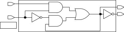
You can use the optional guard expression to control the operation of certain statements within a block. To illustrate this point, Figure 4-3 shows the code description and corresponding schematic for a bistable latch using a guard expression.
1 |
ENTITY bistable_latch IS |
|
2 |
PORT (enable, data: IN |
bit; |
3 |
q, q_not : OUT |
bit ); |
4 |
END bistable_latch; |
|
5 |
|
|
6ARCHITECTURE example OF bistable_latch IS
7BEGIN
8 |
latch1 : |
-- block |
label |
9 |
BLOCK (enable = ’1’) |
-- guard |
expression |
10 |
SIGNAL d_in : bit; |
--block |
decl. item |
11 |
|
|
|
12BEGIN
13d_in <= GUARDED data ; -- guarded sig. assignment
14q <= d_in ;
15q_not <= NOT d_in ;
16END BLOCK latch1 ;
17END example ;
Bistable Latch
DATA |
|
0 |
D_IN |
|
Q |
|
|
|
|
||
|
|
0 |
|
|
|
ENABLE |
|
|
0 |
0 |
Q_NOT |
0 |
|
0 |
0 |
||
Guard |
0 |
0 |
|
|
|
|
0 |
|
|
|
Figure 4-3. Using the Guard Expression on a Bistable Latch
The guard expression (enable = ’1’) in line 9 causes all guarded signal assignments within the block to execute only when the guard expression is true. In the case of the bistable latch, the enable signal must equal a 1 before the guarded signal assignment d_in <= GUARDED data in line 13 will execute. In other words, the d_in signal does not take on the value of the data signal until the enable signal is at a 1 value. (The data value is latched until the enable signal goes high).
4-6 |
Mentor Graphics Introduction to VHDL, July 1994 |