

mentor_instroduction
.pdfCoding Techniques
________________________________________________________________________________________________________________________
declarations. Indentation shows the subordination. Blank lines help break the code into visually discernible units.
Wherever possible, text is aligned in columns such, as lines 5 through 8 of the my_qsim_logic file and lines 10 through 13 of the shifter_architecture file.
Comments are used in the examples found throughout this section to help familiarize you with how to identify basic constructs in real code, such as the port clause comment in line 6 of the shifter_entity file. In your code, use comments to help describe code functionality in areas that are not clear.
Compare the readability of the code in Figure 6-1 with the equivalent code in Figure 6-2. The code in Figure 6-2 ignores all but one guideline (capitalizing reserved words). The code may perform as expected, but it is not very easy to read. If reserved words were not capitalized, it would be almost impossible to read.
Mentor Graphics Introduction to VHDL, July 1994 |
6-3 |
Coding Techniques
________________________________________________________________________________________________________________________
1 |
-----------STORED IN FILE my_qsim_logic-------------------- |
2 |
PACKAGE my_qsim_logic IS --Following is a portion of qsim_logic |
3 |
|
4 |
--Leading ’S’: denotes qsim state |
5 |
TYPE my_qsim_12state IS(SXR,SXZ,SXS,--’Z’: Hi imped. sig. strngth |
6 |
SXI,S0R,S0Z,--’R’: Resistive sig. strength |
7 |
S0S,S0I,S1R,--Trailing ’S’:Strong sig. strth |
8 |
S1Z,S1S,S1I);--’I’:Indeterminate sig. strth |
9 |
TYPE my_qsim_12state_vector IS ARRAY(natural RANGE <>) |
10 |
OF my_qsim_12state; |
11 |
END my_qsim_logic; |
12 |
----------------------------------------------------------------- |
1 |
------------STORED IN FILE shifter_entity------------------- |
2 |
LIBRARY my_lib; USE my_lib.my_qsim_logic.ALL; |
3 |
|
4ENTITY shifter IS
5GENERIC(Prop_delay: time); --time declared in standard package
6 |
PORT (shftin : IN |
my_qsim_12state_vector(0 TO 3); --port cl. |
|
7 |
shftout : OUT |
my_qsim_12state_vector(0 TO 3); |
|
8 |
shftctl : IN |
my_qsim_12state_vector(0 TO 1)); |
|
9 |
END shifter; |
|
|
10 |
----------------------------------------------------------------- |
|
|
1 |
-----------STORED IN FILE shifter_architecture-------------- |
||
2 |
ARCHITECTURE behav1 OF shifter IS |
-- architecture body |
|
3 |
BEGIN |
|
|
4 |
shift_proc: |
|
--process statement |
5PROCESS (shftin, shftctl)
6VARIABLE shifted : my_qsim_12state_vector(0 TO 3);
8 |
BEGIN |
|
9 |
CASE shftctl is |
--process statement part |
10WHEN (S0S, S0S) => shifted := shftin;
11WHEN (S0S, S1S) => shifted := shftin(1 TO 3) & S0S;
12WHEN (S1S, S0S) => shifted := S0S & shftin(0 TO 2);
13WHEN (S1S, S1S) => shifted := shftin(0) & shftin(0 TO 2);
14END CASE;
15shftout <= shifted AFTER Prop_delay;
16END PROCESS shift_proc;
17END behav1;
18 -----------------------------------------------------------------
Figure 6-1. Good Presentation Style for Shifter Description
6-4 |
Mentor Graphics Introduction to VHDL, July 1994 |
Coding Techniques
________________________________________________________________________________________________________________________
1--------STORED IN FILE shifter-----------------------
2TYPE my_qsim_12state IS (SXR,SXZ,SXS,SXI,S0R,S0Z,S0S,S0I,
3S1R,S1Z,S1S,S1I);
4TYPE my_qsim_12state_vector IS ARRAY(natural RANGE <>)
5 |
OF my_qsim_12state; |
6ENTITY shifter IS
7GENERIC (prop_delay : time);
8PORT (shftin : IN my_qsim_12state_vector(0 TO 3);
9shftout : OUT my_qsim_12state_vector(0 TO 3);
10shftctl : IN my_qsim_12state_vector(0 TO 1));
11END shifter;
12ARCHITECTURE behav1 OF shifter IS
13BEGIN
14PROCESS (shftin, shftctl)
15VARIABLE shifted : my_qsim_12state_vector(0 TO 3);
16BEGIN
17CASE shftctl IS
18WHEN (S0S, S0S) => shifted := shftin;
19WHEN (S0S, S1S) => shifted := shftin(1 TO 3) & S0S;
20WHEN (S1S, S0S) => shifted := S0S & shftin(0 TO 2);
21WHEN (S1S, S1S) => shifted := shftin(0) & shftin(0 TO 2);
22END CASE;
23shftout <= shifted AFTER prop_delay;
24END PROCESS;
25END behav1;
26----------------------------------------------------------
Figure 6-2. Poor Presentation Style for Shifter Description
Various Techniques for Modeling Timing
VHDL provides a number of alternatives for modeling timing and other parameters that are dependent on different technologies. Parameters can be embedded in a model either as fixed values or variables, or the parameters can be customized outside the model. These techniques are described in the following subsections using a simple AND gate example.
Mentor Graphics Introduction to VHDL, July 1994 |
6-5 |
Coding Techniques
________________________________________________________________________________________________________________________
Embedding Fixed-Delay Parameters Within a Model
If you want a model that describes one kind of technology, you may choose to embed delay values within the model. The following example of an AND gate (and2_gate) is a simple behavioral model that includes a propagation delay of 8 ns (lines 8 and 10). The behavior of this model might be accurate enough for use in certain simulations.
1 |
ENTITY and2_gate |
IS |
2 |
PORT (in0, in1 |
: IN bit; |
3 |
out1 |
: OUT bit ); |
4 |
END and2_gate; |
|
5 |
|
|
6 |
|
|
7ARCHITECTURE fixed_delay OF and2_gate IS
8CONSTANT Typical_delay : time := 8 ns;
9BEGIN
10out1 <= in0 AND in1 AFTER Typical_delay; --fixed delay
11 END fixed_delay; |
-- of 8 ns |
When dealing with more complicated models, you should declare a constant (as in line 8) to hold your fixed-delay value. Multiple statements in your model may use the delay value, but you can modify the value at a later time in just one place (the constant declaration) of the model. To change the delay value, you have to edit the file and recompile it.
Embedding Variable-Delay Parameters Within a Model
One step up in complexity (and accuracy) from the fixed_delay architecture in the previous example involves a model that has different propagation delays depending on the state of the output. The following example also embeds the delay information in the model but adds a variable-delay to the output.
6-6 |
Mentor Graphics Introduction to VHDL, July 1994 |
Coding Techniques
________________________________________________________________________________________________________________________
1LIBRARY my_lib; --Define Logical library name.
2USE my_lib.logic_example.ALL; --Calls package that defines
3 |
|
|
--my_lsim_LOGIC. See Figure 6-15, |
|
4 |
ENTITY and2_gate |
IS |
-- |
page 6-28. |
5 |
PORT (in0, in1 |
: IN |
my_lsim_LOGIC; |
|
6 |
out1 |
: OUT my_lsim_LOGIC ); |
|
|
7 |
END and2_gate; |
|
|
|
8 |
|
|
|
|
9 |
|
|
|
|
10ARCHITECTURE variable_delay OF and2_gate IS
11CONSTANT Tplh_typ: time:= 5 ns; --low-to-high typ. delay
12CONSTANT Tphl_typ: time:= 8 ns; --high-to-low typ. delay
14BEGIN
15and_inputs : PROCESS (in0, in1)
16BEGIN
17IF (in0 AND in1) = ’1’ THEN
18out1 <= ’1’ AFTER Tplh_typ;
19ELSIF (in0 AND in1) = ’0’ THEN
20out1 <= ’0’ AFTER Tphl_typ;
21ELSIF (Tplh_typ >= Tphl_typ) THEN
22out1 <= ’X’ AFTER Tplh_typ;
23ELSE
24out1 <= ’X’ AFTER Tphl_typ;
25END IF;
26END PROCESS and_inputs;
27END variable_delay;
Figure 6-3. Embedding Variable-Delay Parameters Within Model
In the variable_delay architecture, two constants are declared: one to hold the delay value of a low-to-high transition (line 11), and one to hold the delay value of a high-to-low transition (line 12). These delay values are used in the process (and_inputs) that determine which state has occurred (with if/else conditions) at the inputs and sets the output accordingly. Wherever the constant Tplh_typ is used, a delay value of 5 ns occurs; similarly, wherever constant Tphl_typ is used, a delay value of 8 ns occurs.
This model does not actively take into account ’X’ (unknown) or ’Z’ (high impedance) states on the inputs. These conditions could be trapped in "if conditions" and appropriate action taken accordingly.
Mentor Graphics Introduction to VHDL, July 1994 |
6-7 |
Coding Techniques
________________________________________________________________________________________________________________________
The next example uses generics instead of constants to gather and pass the delay information to the model architecture.
Using Generics to Parameterize a Model
In this subsection a behavioral model of an AND gate is used to show one way a model can accept different propagation timing values for the output signal from outside the model. This technique can be used to pass any parameters such as load capacitance and temperature
The and2_gate model is shown in Figure 6-5. The generic clause (line 22) allows you to parameterize a rise and fall time of the out1 signal with values from outside the model in either a compiled VHDL test bench file containing a generic map, shown in Figure 6-4, or by some other implementation-dependent method.
1LIBRARY my_lib; --Define Logical library name.
2USE my_lib.my_qsim_logic.ALL;
3ENTITY test_and2_gate IS
4END test_and2_gate;
5
6
7ARCHITECTURE test_bench OF test_and2_gate IS
8COMPONENT and2
9GENERIC (Rs, Fl : time );
10PORT(a,b: IN my_qsim_12state; c: OUT my_qsim_12state);
11END COMPONENT;
12
13FOR a1 :and2 USE ENTITY and2_gate(behav)
14GENERIC MAP (Rs, Fl)
15PORT MAP (a, b, c);
16SIGNAL x, y, z : my_qsim_12state;
17BEGIN
18a1: and2
19GENERIC MAP (7 ns, 10 ns);
20PORT MAP (x ,y, z);
21. . . --The code here can exercise the AND gate.
22END test_bench;
Figure 6-4. Test Bed Code for AND Gate Model
6-8 |
Mentor Graphics Introduction to VHDL, July 1994 |
Coding Techniques
________________________________________________________________________________________________________________________
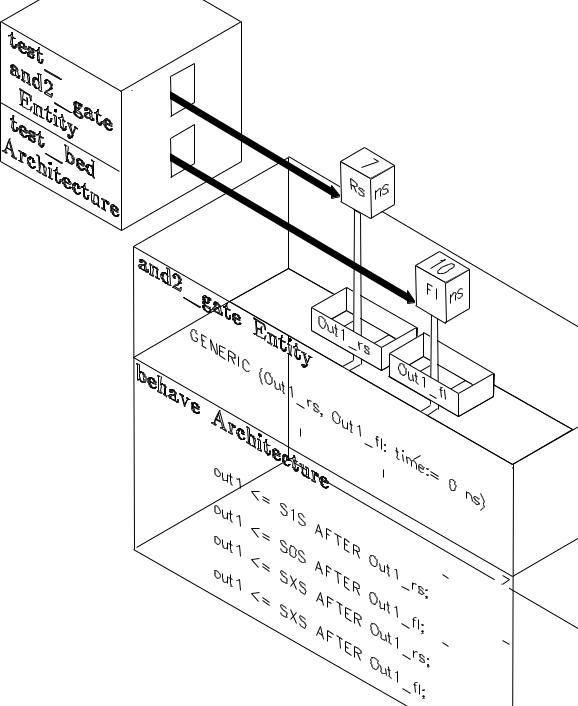
After the and2_gate model is compiled, the test_and2_gate model can be compiled. At that time the values from the VHDL test bench file are passed into the and2_gate VHDL model as shown in Figure 6-6. In this example, the Rs value is set to 7 ns and the Fl value is set to 10 ns (line 19 of the test_bed architecture in Figure 6-4). Where the and2_gate model in Figure 6-5 uses out1_rs (lines 32, 36, and 37), the value 7 ns is inserted. Similarly, where out1_fl is used in the and2_gate model (lines 35, 36, and 39 in Figure 6-5), the Fl value of 10 ns is inserted.
As shown in line 22 of Figure 6-5, you can set default values for the generic parameters. The default takes affect if there is no value associated with the signal from outside the and2_gate model. Default binding also occurs by other ways when certain conditions are met.
Mentor Graphics Introduction to VHDL, July 1994 |
6-9 |
Coding Techniques
________________________________________________________________________________________________________________________
1 |
PACKAGE my_qsim_logic IS --Package defines qsim_12state |
|
2 |
--and function qsim_state_from(), |
|
3 |
--which returns qsim_state value. |
|
4 |
TYPE my_qsim_state IS (’X’,’0’,’1’,’Z’);--X: Unknown logic level |
|
5 |
SUBTYPE my_qsim_value IS qsim_state RANGE ’X’ TO ’1’ ; |
|
6 |
--Leading S: denotes qsim state |
|
7 |
TYPE my_qsim_12state IS(SXR,SXZ,SXS,--Z: Hi imped. sig. strngth |
|
8 |
SXI,S0R,S0Z, --R: Resistive sig. strngth |
|
9 |
S0S,S0I,S1R, --Trailing S: Strong sig. strth |
|
10 |
S1Z,S1S,S1I);--I: Indeterminate sig. strth |
|
11 |
-- CONVERSION TABLE |
|
12 |
FUNCTION my_qsim_state_from(val: my_qsim_12state)-- State |
Result |
13 |
RETURN my_qsim_state;--S0S, S0R, |
’0’ |
14 |
--S1S, S1R, |
’1’ |
15 |
--S0I, S1I, SXS, SXR, SXI ’X’ |
|
16 |
--SXZ, S0Z, S1Z ’Z’ |
|
17 |
END my_qsim_logic; --PACKAGE BODY NOT SHOWN HERE. |
|
18 |
|
|
19 |
|
|
20USE my_qsim_logic.ALL;
21ENTITY and2_gate IS
22GENERIC (Out1_rs, Out1_fl: time := 0 ns);
23PORT (in0, in1 : IN my_qsim_12state;
24 |
out1 : OUT my_qsim_12state ); |
25 |
END and2_gate; |
26 |
|
27ARCHITECTURE behave OF and2_gate IS
28BEGIN
29and_inputs : PROCESS (in0, in1)
30BEGIN
31IF((my_qsim_state_from(in0) AND my_qsim_state_from(in1))= ’1’)
32THEN out1 <= S1S AFTER Out1_rs;
33ELSIF ((my_qsim_state_from(in0) AND
34 |
my_qsim_state_from(in1)) =’0’) |
35THEN out1 <= S0S AFTER Out1_fl;
36ELSIF (Out1_rs >= Out1_fl) THEN
37out1 <= SXS AFTER Out1_rs;
38ELSE
39out1 <= SXS AFTER Out1_fl;
40END IF;
41END PROCESS and_inputs;
42END behave;
Figure 6-5. AND Gate Model Using Generics to Receive Timing Parameters
6-10 |
Mentor Graphics Introduction to VHDL, July 1994 |
Coding Techniques
________________________________________________________________________________________________________________________
|
|
|
|
|
|||
|
|||
|
|||
|
|
|
|
|
|
|
|
|
|
|
|
|
|
|
|
|
|
|
|
|
|
|
|
|
|
|
|
|
|
|
|
|
|||
|
|||
|
|
||
|
|
||
|
|
||
|
|
||
|
|
||
|
|
||
|
|
||
|
|
||
|
|
||
|
|||
|
|||
|
|
||
|
|
||
|
|||
|
|||
|
|||
|
|||
|
|||
|
|||
|
|||
|
|||
|
|||
|
|||
|
|||
|
|
|
|
|
|
|
|
|
|
|
|
|
|
|
|
|
|
|
|
|
|||
|
|||
|
|||
|
|||
|
|||
|
|||
|
|
|
|
|
|
|
|
|
|
|
|
|
|
|
|
|
|
|
|
|
|
|
|
|
|
|
|
|
|
|
|
|
|
|
|
|
|
|
|
|
|
|
|
|
|
|
|
|
|
|
|
|
|
|
|
|
|
|
|
|
|
|
|
|
|
|
|
|
|
|
|
Figure 6-6. Using Generics to Pass Customized Parameters to a Model
Mentor Graphics Introduction to VHDL, July 1994 |
6-11 |
Coding Techniques
________________________________________________________________________________________________________________________
Parameterizing Rise/Fall Delays with Generics
The example in Figure 6-7 shows the entity declaration (interface) for a one-bit latch description that includes parameterized rise and fall delays. The rise and fall delay values are set in a related VHDL test bench file. The values from the compiled test bench model are passed into the latch model through generics. The latch code in Figure 6-7 reserves space for error checking code that is added and described in the following subsection.
Unlike the previous and2_gate design entity in Figure 6-5, the rise/fall delay values for the latch design entity are treated in the VHDL model as strings. Lines 17 through 20 of Figure 6-7 define the generic rise/fall constants that are passed into the model. Each of the rise/fall constants is declared as a string and given a default value of "0, 0, 0". If the latch model is instantiated in another model without a generic map to set the corresponding propagation delay values, the default values are used. This string assumes the first number is the minimum delay, the second number is the typical delay, and the third number is the maximum delay (in nanoseconds). Line 21 receives the timing mode information.
A function called "my_qsim_get_time" is declared in package "my_qsim_extended" (not shown), which chooses the appropriate delay value from each generic constant string based on which timing parameter is chosen (min, max, or typ). To choose the correct string, a type is also defined in the "my_qsim_extended" package (timing_type) and has a value set of min (minimum), typ (typical), or max (maximum). You assign one of the following values: min, typ, or max to Timing_mode in a generic map in a test bench file or other implementation-dependent method. Line 2 in Figure 6-7 calls the my_qsim_extended package to make the my_qsim_get_time function and the timing_mode type visible to the latch design entity. Lines 28 through 32 in Figure 6-7 also describe the my_qsim_get_time function.
Figure 6-8 illustrates how a string is passed to the latch design entity for each rise and fall value on the enable and data signals. Once the strings are passed to the model, the appropriate value (min, typ, or max) from each string must be selected and converted to type time.
6-12 |
Mentor Graphics Introduction to VHDL, July 1994 |