

mentor_instroduction
.pdfVHDL Fundamentals
________________________________________________________________________________________________________________________
if statement ..................... |
if condition then |
|
sequence_of_statements |
|
elsif condition then |
|
sequence_of_statements |
|
else |
|
sequence_of_statements |
|
end if ; |
The VHDL if statement is interpreted similarly to an English sentence. For example, look at the following sentence:
If the traffic light is green, then proceed across the intersection or else (if the traffic light is not green) remain stopped.
The sentence has a condition that must be satisfied (If the traffic light is green) before the command (proceed across the intersection) is executed. The "else" part of the sentence gives the alternative command (or else remain stopped) if the condition is not satisfied.
The if statement in Figure 2-10 (lines 10 through 14) can be rewritten as the following sentence:
If signal sel (select) is equal to 0, then assign the value of the waveform on signal d1 to target signal q or else assign the value of the waveform on signal d0 to target signal q.
Once the if condition or the else condition in this example is satisfied
(sel = ’0’ or its opposite where sel does not equal ’0’), target signal q is modified according to the appropriate signal assignment statement. The basic format of a signal assignment statement is as follows:
signal assignment statement: target <= transport waveform ; (Note that transport is optional.)
The following is the first signal assignment statement in Figure 2-10:
11 |
q <= d1; |
Mentor Graphics Introduction to VHDL, July 1994 |
2-17 |
VHDL Fundamentals
________________________________________________________________________________________________________________________
This statement assigns the waveform on signal d1 to target signal q. The optional reserved word transport* is not used in this example. The signal assignment delimiter consists of the two adjacent special characters <=, also called a compound delimiter. The following is the second signal assignment statement in this example. This statement assigns the waveform of signal d0 to the target signal q:
13 |
q <= d0; |
Another use of the compound delimiter <= is as the relational operator "less than or equal to" in conditions such as the following:
IF z <= ’1’ THEN
The other relational operators are shown in Table 5-1 on page 5-11.
In summary, the signal assignment delimiter <= is used to assign the value on the right side of the delimiter to the target on the left side. The same compound delimiter <= is used as the relational operator "less than or equal to" in test conditions such as the if statement. How this delimiter is used in context determines whether it is a signal assignment delimiter or a relational operator.
Figure 2-11 shows a VHDL behavioral description of a four-bit shifter. To see how accurate and succinct the VHDL description is, compare it with the following textual description:
The four-bit shifter has four input data lines, four output data lines, and two control lines. When both control lines are low, the input levels are passed directly to the corresponding output. When control line 0 is high and control line 1 is low, output line 0 is low; input line 0 is passed to output line 1; input line 1 is passed to output line 2; and input line 2 is passed to output line 3. When control line 0 is low and control line 1 is high, input line 1 is passed to output line 0; input line 2 is passed to output line 1; input line 3 is passed to output line 2; and output line 3 is low. When both control lines are high, input line 0 is passed to both output line 0 and line 1; input line 1 is passed to output line 2; and input line 2 is passed to output line 3.
________________
*Refer to the Glossary entry for the reserved word transport for further information.
2-18 |
Mentor Graphics Introduction to VHDL, July 1994 |
VHDL Fundamentals
________________________________________________________________________________________________________________________
1 |
ENTITY shifter IS |
-- entity declaration |
2 |
PORT ( shftin : IN |
bit_vector(0 TO 3); --port clause |
3 |
shftout : OUT bit_vector(0 TO 3); |
|
4 |
shftctl : IN |
bit_vector(0 TO 1) ); |
5 |
END shifter; |
|
6 |
|
|
7 |
ARCHITECTURE behav OF shifter IS -- architecture body |
|
8 |
BEGIN |
|
9 |
f2: |
-- process statement |
10PROCESS (shftin, shftctl)
11VARIABLE shifted : bit_vector(0 TO 3);--proc. decl. part
12BEGIN
13 |
CASE shftctl IS |
--proc. stmnt part |
14WHEN "00" => shifted := shftin;
15WHEN "01" => shifted := shftin(1 TO 3) & ’0’;
16WHEN "10" => shifted := ’0’ & shftin(0 TO 2);
17WHEN "11" => shifted := shftin(0) & shftin(0 TO 2);
18END CASE;
19shftout <= shifted AFTER 10 ns;
20END PROCESS f2;
21END behav;
Figure 2-11. Code Example of Behavioral Description for a Shifter
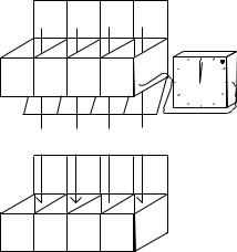
The port clause in Figure 2-11 (lines 2 through 4) identifies the input ports as shftin (shifter data in) and shftctl (shifter control) and the output port as shftout (shifter data out). This port clause defines the input and output ports as an array of bits using the predefined type bit_vector. Types are described on page 3-1.
The arrays can be compared with containers that have labeled compartments for data storage as shown in Figure 2-12. For example, the array named shftin has four elements referred to as shftin(0), shftin(1), shftin(2), and shftin(3). Each element is a storage area for data; in this case, they are storage areas for bit information.
Mentor Graphics Introduction to VHDL, July 1994 |
2-19 |

VHDL Fundamentals
________________________________________________________________________________________________________________________
shftin 0 |
1 |
2 |
3 |
shftout 0 |
1 |
2 |
3 |
shftctl 0 |
1 |
|
|
|
|
|
|
|
|
|
|
|
|
|
|
|
|
|
|
|
|
|
|
|
|
|
|
|
|
|
|
|
|
|
|
|
|
|
|
|
|
|
|
|
|
|
|
|
|
Figure 2-12. Arrays Represented as Data-Storage Containers
The architecture body in Figure 2-11 contains a process statement (lines 9 through 20) as does the previous MUX behavioral example. One difference between the two examples is that the process statement in the shifter example contains a process declarative part (line 11) composed of a variable declaration. A variable declaration has the following format:
variable declaration .......... |
variable identifier_list : |
|
subtype_indication := expression ; |
The variable declaration in Figure 2-11 does not include the optional
":= expression" part. The variable shifted holds the shifted value of the shftin bit vector. It is important that shftin and shifted are of the same type, in this case, an array of bits with four elements.
The variable declaration states that shifted is an array of bits from 0 to 3. The bit vector shifted appears later (after the case statement) in the signal assignment:
19 shftout <= shifted AFTER 10 ns;
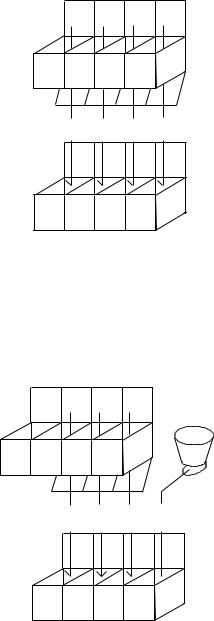
This signal assignment statement includes the reserved word after to specify the propagation time expected for the shftin array of waveforms (stored in the variable array shifted) to reach the shftout array of target signals. Figure 2-13 shows how the elements in array shifted map one-for-one to the elements in array shftout. The 10 ns delay is represented by a timer that determines the time when the waveforms are transferred. Labels S0 through S3 represent the values that were stored in shftin and then passed to the variable shifted.
2-20 |
Mentor Graphics Introduction to VHDL, July 1994 |
VHDL Fundamentals
________________________________________________________________________________________________________________________
shifted |
0 |
1 |
2 |
3 |
|
||||
|
||||
|
||||
|
||||
|
||||
|
||||
|
||||
|
||||
|
||||
|
|
|||
|
|
|||
|
|
|||
|
|
|||
S0 S1 S2 S3
shftout 0 1 2 3
|
|
|
|
|
|
|
|
|
|
|
|
|
Figure 2-13. Variable Assignment for SHFTOUT Array After 10 ns
The previous MUX behavioral example uses an if statement to assign a waveform to a target signal when a given condition is satisfied. The shifter example uses a case statement to perform a similar function. A case statement executes one out of a number of possible sequences of statements as determined by the value of an associated expression. The basic format of a case statement is shown as follows:
case statement ................. |
case expression is |
|
when choices => --case stmnt alternative |
|
sequence_of_statements |
|
end case ; |
The case statement in Figure 2-11 (lines 13 through 18 in the process statement part) contains four case statement alternatives for the shftctl array, shftctl(0) and shftctl(1). When one of the alternatives is true, the associated variable assignment statement is executed. A variable assignment statement replaces the current variable value (target) with a new value as specified by an expression. A variable assignment statement has the following format:
variable assignment stmnt |
target := expression |
Mentor Graphics Introduction to VHDL, July 1994 |
2-21 |
VHDL Fundamentals
________________________________________________________________________________________________________________________
The characters := are used together as the variable assignment delimiter. To better understand the variable assignment process, consider each of the case statement alternatives from Figure 2-11 one at a time starting with the following:
14 WHEN "00" => shifted := shftin;
According to this case statement alternative, when shftctl(0) equals 0 and shftctl(1) equals 0, then the variable array shifted is assigned the values in the array shftin. The compound delimiter ’=>’ separates the choices (WHEN "00") from the sequence of statements (shifted := shftin;).
The alignment of data in an array is determined by the order in which the array is declared. The port clause defines array shftctl as follows:
4 shftctl : IN bit_vector(0 TO 1)
The order of data in the array shftctl is 0 to 1 (ascending). Any reference to shftctl follows this ordering. Therefore, the first 0 (from the left) in the phrase WHEN "00" refers to the state of shftctl(0) and the second 0 (from the left) refers to the state of
The order of data in the arrays shftin and shftout is defined in the port clause as 0 to 3 (ascending order). The variable shifted is defined in the process declarative part as 0 to 3 (ascending).
Figure 2-14 shows how the elements in array shftin map one-for-one to the elements in array shifted during execution of the following case statement alternative:
14 WHEN "00" => shifted := shftin;
Labels V0 through V3 represent the values that are passed from each shftin array element.
2-22 |
Mentor Graphics Introduction to VHDL, July 1994 |
VHDL Fundamentals
________________________________________________________________________________________________________________________
shftin 0 1 2 3
|
|
|
|
|
|
|
|
|
|
|
|
V0 V1 V2 V3
shifted 0 1 2 3
|
|
|
|
|
|
|
|
|
|
|
|
Figure 2-14. Variable Assignment for Array When SHFTCTL = 00
Figure 2-15 shows how the elements in array shftin map to the elements in array shifted during execution of the following case statement alternative:
15 WHEN "01" => shifted := shftin(1 TO 3) & ’0’;
shftin 0 1 2 3
|
|
|
|
|
|
|
|
|
|
|
|
|
V1 V2 V3 ’0’
shifted 0 1 2 3
|
|
|
|
|
|
|
|
|
|
|
|
|
Figure 2-15. Variable Assignment for Array When SHFTCTL = 01
Note that only three elements (1, 2, and 3) of the shftin array are transferred to the shifted array. The fourth value (’0’) is concatenated to the arrayshftin by using the concatenation operator &. The ’0’ is transferred along with the other shftin values. For a complete description of the concatenation operator, see the
Mentor Graphics Introduction to VHDL, July 1994 |
2-23 |

VHDL Fundamentals
________________________________________________________________________________________________________________________
"Adding Operators" section in the Mentor Graphics VHDL Reference Manual.
Figure 2-16 shows how the elements in array shftin map to the elements in array shifted during execution of the following case statement alternative:
16 WHEN "10" => shifted := ’0’ & shftin(0 TO 2);
In this alternative, the value ’0’ is assigned to the first element of arrayshifted (shifted(0)) and the values of shftin(0 to 2) are concatenated to the ’0’ and assigned to array elements shifted(1) through shifted(3).
shftin |
0 |
1 |
2 |
3 |
|
|
|
||||
|
|
||||
|
|
||||
|
|
||||
|
|
||||
|
|
||||
|
|
||||
|
|
||||
|
|
||||
|
|
|
|||
|
|
|
|||
|
|
|
|||
|
|
|
|||
|
’0’ |
V0 V1 V2 |
|
||
shifted |
0 |
1 |
2 |
3 |
|
|
|
|
|
|
|
|
|
|
|
|
|
|
Figure 2-16. Variable Assignment for Array When SHFTCTL = 10
Figure 2-17 shows how the elements in array shftin map to the elements in array shifted during execution of the following case statement alternative:
17 WHEN "11" => shifted := shftin(0) & shftin(0 to 2);
The value of shftin(0) is assigned to two elements of array shifted
(shifted(0) and shifted(1)).
2-24 |
Mentor Graphics Introduction to VHDL, July 1994 |

VHDL Fundamentals
________________________________________________________________________________________________________________________
shftin |
0 |
1 |
2 |
3 |
|
|
|
||||
|
|
||||
|
|
||||
|
|
||||
|
|
||||
|
|
||||
|
|
||||
|
|
||||
|
|
|
|||
|
|
|
|||
|
|
|
|||
|
|
|
|||
|
V0 V0 V1 V2 |
|
|||
shifted |
0 |
1 |
2 |
3 |
|
|
|
|
|
|
|
|
|
|
|
|
|
|
|
|
|
|
|
|
|
|
|
|
|
|
|
Figure 2-17. Variable Assignment for Array When SHFTCTL = 11
To show further what happens when process f2 is executed in the VHDL shifter example, three conditions of the shftctl array are represented in the waveform drawing of Figure 2-18 as follows:
1.WHEN "00" => shifted := shftin;
2.WHEN "10" => shifted := ’0’ & shftin(0 to 2);
3.WHEN "01" => shifted := shftin(1 to 3) & ’0’;
Each number at the top of the waveform drawing relates to the corresponding condition in the previous numbered list. Arbitrary waveforms (data values) have been assigned to the shftin array elements shftin(3) to shftin(0). The values of the shftin array elements are labeled V3 to V0 for each condition represented. The arrows show how the values flow from the shftin array to the shifted array (when the shftctl signals change state) and then to the shftout array 10 ns later.
Mentor Graphics Introduction to VHDL, July 1994 |
2-25 |
VHDL Fundamentals
________________________________________________________________________________________________________________________
1.Because shftctl(1) and shftctl(0) are both low in condition 1, the values on shftin(3) to shftin(0) (V3 to V0) pass to the corresponding
shifted array elements. Ten nanoseconds later, the same values pass from the shifted array elements to the shftout array elements as determined by the conditional signal assignment:
19 shftout <= shifted AFTER 10 ns;
A conditional signal assignment is further described on page 2-31.
2.Because shftctl(1) is high and shftctl(0) remains low in condition 2, the following conditions occur: a low (0) is forced on shifted(0), shifted(1) takes on the high value from shftin(0), shifted(2)
remains high because of the high value from shftin(1), and shifted(3) takes on the low value from shftin(2).
3.Because shftctl(1) is low and shftctl(0) is high in condition 3, the following conditions occur: a low (0) is forced on shifted(3) so it remains low, shifted(0) takes on the low value from shftin(1) so it remains low, shifted(1) takes on the low value from shftin(2), and shifted(2) takes on the low value from shftin(3).
To provide a complete picture of the four-bit shifter example, the structure is shown in the schematic of Figure 2-19.
2-26 |
Mentor Graphics Introduction to VHDL, July 1994 |