

ADSP-TS101S
Link Ports Data Transfer and Token Switch Timing
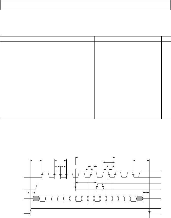
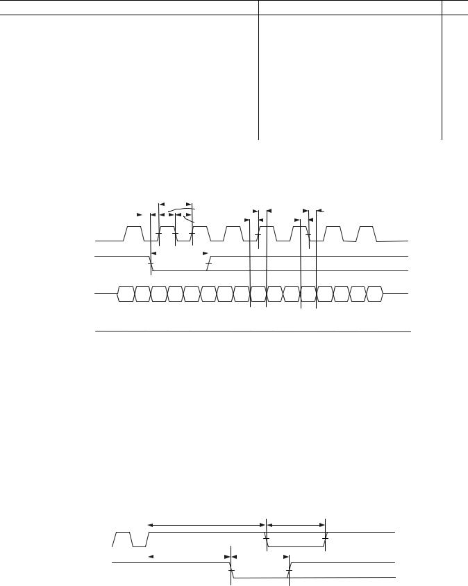
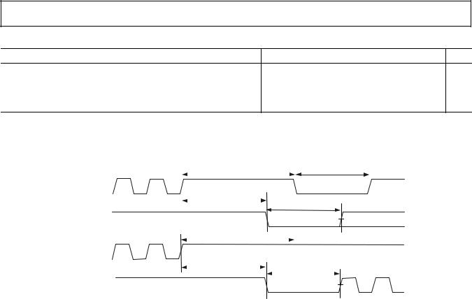
Table 20, Table 21, Table 22, and Table 23 with Figure 11, Figure 12, Figure 13, and Figure 14 provide the timing specifications for the link ports data transfer and token switch.
Table 20. Link Ports—Transmit
Parameter |
Min |
Max |
Unit |
Timing Requirements |
|
|
|
|
1 |
Connectivity Pulse Setup |
2 × tCCLK + 3.5 |
|
ns |
tCONNS |
|
|||
2 |
Connectivity Pulse Setup |
8 |
|
ns |
tCONNS |
|
|||
3 |
Connectivity Pulse Input Width |
tLXCLK_TX + 1 |
|
ns |
tCONNIW |
|
|||
tACKS |
Acknowledge Setup |
0.5 × tLXCLK_TX |
|
ns |
Switching Characteristics |
|
|
|
|
4 |
Transmit Link Clock Period |
0.9 × LR × tCCLK |
1.1 × LR × tCCLK |
ns |
tLXCLK_TX |
||||
1 |
Transmit Link Clock Width High |
0.33 × tLXCLK_TX |
0.66 × tLXCLK_TX |
ns |
tLXCLKH_TX |
||||
2 |
Transmit Link Clock Width High |
0.4 × tLXCLK_TX |
0.6 × tLXCLK_TX |
ns |
tLXCLKH_TX |
||||
1 |
Transmit Link Clock Width Low |
0.33 × tLXCLK_TX |
0.66 × tLXCLK_TX |
ns |
tLXCLKL_TX |
||||
2 |
Transmit Link Clock Width Low |
0.4 × tLXCLK_TX |
0.6 × tLXCLK_TX |
ns |
tLXCLKL_TX |
||||
tDIRS |
LxDIR Transmit Setup |
0.5 × tLXCLK_TX |
2 × tLXCLK_TX |
ns |
tDIRH |
LxDIR Transmit Hold |
0.5 × tLXCLK_TX |
2 × tLXCLK_TX |
ns |
1 |
LxDAT7–0 Output Setup |
0.25 × tLXCLK_TX – 1 |
|
ns |
tDOS |
|
|||
1 |
LxDAT7–0 Output Hold |
0.25 × tLXCLK_TX – 1 |
|
ns |
tDOH |
|
|||
2 |
LxDAT7–0 Output Setup |
0.17 × tLXCLK_TX – 1 |
|
ns |
tDOS |
|
|||
2 |
LxDAT7–0 Output Hold |
0.17 × tLXCLK_TX – 1 |
|
ns |
tDOH |
|
|||
tLDOE |
LxDAT7–0 Output Enable |
1 |
|
ns |
5 |
LxDAT7–0 Output Disable |
1 |
|
ns |
tLDOD |
|
|||
1The formula for this parameter applies when LR is 2.
2The formula for this parameter applies when LR is 3, 4, or 8.
3LxCLKIN shows the connectivity pulse with each of the three possible transitions to “Acknowledge.” After a connectivity pulse low minimum, LxCLKIN may [1] return high and remain high for “Acknowledge,” [2] return high and subsequently go low (meeting tacks) for “Not Acknowledge,” or [3] remain low for “Not Acknowledge.”
4The Link clock Ratio (LR) is 2, 3, 4, or 8 as set by the SPD bits in the LCTLx register.
5This specification applies to the last data byte or the “Dummy” byte that follows the verification byte if enabled. For more information, see the TigerSHARC DSP Hardware Specification.
|
|
|
|
tCONNS |
||
tDIRS |
|
tLxCLK_Tx |
|
|
|
tDIRH |
|
|
tACKS |
||||
|
|
|
|
|
||
|
|
|
|
|
tDOH |
|
tDOH |
|
|
tLxCLKH_Tx |
|
|
tLxCLKL_Tx |
tDOS |
|
tDOS |
|
|
|
|
|
|
|
|
|
|
|
||
1 |
|
3 |
5 |
7 |
|
9 |
11 |
13 |
15 |
LxCLKOUT |
2 |
|
4 |
6 |
8 |
10 |
|
12 |
14 |
0 |
|
|
|||||||
|
|
|
|
tCONNIW |
|
|
|
|
|
LxCLKIN |
|
|
|
|
|
|
|
|
|
tLDOE |
|
|
|
|
|
|
|
|
tLDOD |
LxDAT7–0 |
|
|
|
|
|
|
|
|
|
LxDIR |
|
|
|
|
|
|
|
|
|
Figure 11. Link Ports—Transmit
REV. 0 |
–25– |
ADSP-TS101S
Table 21. Link Ports—Receive
Parameter |
Min |
Max |
Unit |
Timing Requirements |
|
|
|
|
|
|
|
|
|
|
|
|
|
|
|
|
|
|
|
|
|
|
|
|
|
|
|
|||||||
1 |
Receive Link Clock Period |
|
|
|
|
|
|
0.9 |
× LR × tCCLK |
|
1.1 × LR × tCCLK |
ns |
||||||||||||||||||||||
tLXCLK_RX |
|
|
|
|
|
|
|
|||||||||||||||||||||||||||
tLXCLKH_RX2 |
Receive Link Clock Width High |
|
|
|
|
|
|
|
|
|
0.33 × tLXCLK_RX |
|
0.66 × tLXCLK_RX |
ns |
||||||||||||||||||||
3 |
Receive Link Clock Width High |
|
|
|
|
|
|
0.4 |
× tLXCLK_RX |
|
0.6 × tLXCLK_RX |
ns |
||||||||||||||||||||||
tLXCLKH_RX |
|
|
|
|
|
|
|
|||||||||||||||||||||||||||
2 |
Receive Link Clock Width Low |
|
|
|
|
|
|
|
|
|
0.33 × tLXCLK_RX |
|
0.66 × tLXCLK_RX |
ns |
||||||||||||||||||||
tLXCLKL_RX |
|
|
|
|
|
|
|
|
|
|
||||||||||||||||||||||||
3 |
Receive Link Clock Width Low |
|
|
|
|
|
|
0.4 |
× tLXCLK_RX |
|
0.6 × tLXCLK_RX |
ns |
||||||||||||||||||||||
tLXCLKL_RX |
|
|
|
|
|
|
|
|||||||||||||||||||||||||||
tDIS |
LxDAT7–0 Input Setup |
|
|
|
|
|
|
0.6 |
|
|
|
|
|
|
|
|
|
ns |
||||||||||||||||
tDIH |
LxDAT7–0 Input Hold |
|
|
|
|
|
|
|
|
|
|
|
0.6 |
|
|
|
|
|
|
|
|
|
ns |
|||||||||||
Switching Characteristics |
|
|
|
|
|
|
|
|
|
|
|
|
|
|
|
|
|
|
|
|
|
|
|
|
|
|
|
|||||||
tCONNV |
Connectivity Pulse Valid |
|
|
|
|
|
|
0 |
|
|
|
|
|
|
|
|
|
2.5 × tLXCLK_RX |
ns |
|||||||||||||||
tCONNOW |
Connectivity Pulse Output Width |
|
|
|
1.5 |
× tLXCLK_RX |
|
|
ns |
|||||||||||||||||||||||||
1The link clock ratio (LR) is 2, 3, 4, or 8 as set by the SPD bits in the LCTLx register. |
|
|
|
|
|
|
|
|
|
|
||||||||||||||||||||||||
2The formula for this parameter applies when LR is 2. |
|
|
|
|
|
|
|
|
|
|
|
|
|
|
|
|
|
|
|
|
|
|
||||||||||||
3The formula for this parameter applies when LR is 3, 4, or 8. |
|
|
|
|
|
|
|
|
|
|
|
|
|
|
|
|
|
|
|
|
|
|
||||||||||||
|
|
|
|
|
|
|
|
|
tLxCLK_Rx |
|
|
|
|
|
|
|
|
|
|
|
|
|
|
|
|
|
|
|
|
|
|
|||
|
tCONNV |
|
|
|
|
|
|
|
|
|
|
|
tLxCLKH_Rx |
tDIS |
|
tDIH |
tDIS |
|
tDIH |
|
|
|
||||||||||||
|
|
|
|
|
|
|
|
|
|
|
|
|
|
|
||||||||||||||||||||
|
|
|
|
|
|
|
|
|
|
|
tLxCLKL_Rx |
|
|
|
|
|
|
|
|
|
|
|
|
|
||||||||||
|
|
|
|
|
|
|
|
|
|
|
|
|
|
|
|
|
|
|
|
|
|
|
|
|||||||||||
|
|
|
|
|
|
|
|
|
|
|
|
|
|
|
|
|
|
|
|
|
|
|
|
|
|
|
|
|
13 |
15 |
|
|||
|
|
|
1 |
|
|
3 |
|
5 |
7 |
|
|
|
|
|
|
|
9 |
|
|
11 |
|
|
||||||||||||
|
LxCLKIN |
|
|
|
|
|
|
|
|
|
|
|
|
|
|
|
|
|
|
|
|
|
|
|
|
|
|
|
|
|
|
14 |
|
|
|
|
|
|
|
|
|
|
|
|
|
|
|
|
|
|
|
|
|
|
|
|
|
|
|
|
|
|
|
||||||
|
0 |
|
|
|
|
|
|
2 |
|
|
|
4 |
|
|
6 |
|
|
8 |
|
|
10 |
12 |
|
|
||||||||||
|
|
|
|
|
|
|
|
|
tCONNOW |
|
|
|
|
|
|
|
|
|
|
|
|
|
|
|
|
|
|
|
|
|
|
|||
|
|
|
|
|
|
|
|
|
|
|
|
|
|
|
|
|
|
|
|
|
|
|
|
|
|
|
|
|
|
|||||
|
LxCLKOUT |
|
|
|
|
|
|
|
|
|
|
|
|
|
|
|
|
|
|
|
|
|
|
|
|
|
|
|
||||||
|
LxDAT7–0 |
|
|
|
|
|
|
|
|
|
|
|
|
|
|
|
|
|
|
|
|
|
|
|
|
|
|
|
||||||
|
|
|
|
|
|
|
|
|
|
|
|
|
|
|
|
|
|
|
|
|
|
|
|
|
|
|
|
|||||||
|
LxDIR |
|
|
|
|
|
|
|
|
|
|
|
|
|
|
|
|
|
|
|
|
|
|
|
|
|
|
|
||||||
|
|
|
|
|
|
|
|
|
|
Figure 12. Link Ports—Receive |
|
|
|
|
|
|
|
|||||||||||||||||
Table 22. Link Ports—Token Switch, Token Master |
|
|
|
|
|
|
|
|
|
|
|
|
|
|
|
|
|
|
|
|||||||||||||||
|
|
|
|
|
|
|
|
|
|
|
|
|
|
|
|
|
|
|
|
|
|
|
|
|
|
|
|
|
|
|
|
|
|
|
Parameter |
|
|
|
|
|
|
|
|
|
|
|
|
|
|
|
|
|
|
|
|
|
Min |
|
|
|
|
|
Max |
Unit |
|||||
|
|
|
|
|
|
|
|
|
|
|
|
|
|
|
|
|
|
|
|
|
|
|
|
|
|
|
|
|
|
|
|
|
|
|
Timing Requirements |
|
|
|
|
|
|
|
|
|
|
|
|
|
|
|
|
|
|
|
|
|
|
|
|
|
|
|
|||||||
tREQI |
Token Request Input Width |
|
|
|
|
|
|
|
|
5.0 |
× tLXCLK_RX |
|
|
ns |
||||||||||||||||||||
tTKRQ |
Token Request from Token Enable1 |
|
|
|
|
|
|
|
|
|
|
|
|
|
|
|
|
|
3.0 × tLXCLK_TX |
ns |
||||||||||||||
Switching Characteristics |
|
|
|
|
|
|
|
|
|
|
|
|
|
|
|
|
|
|
|
|
|
|
|
|
|
|
|
|||||||
tTKENO |
Token Switch Enable Output |
|
|
|
|
|
|
|
|
8.0 |
× tLXCLK_TX |
|
|
ns |
||||||||||||||||||||
tREQO |
Token Request Output Width2 |
|
|
|
|
|
|
|
|
6.0 |
× tLXCLK_TX |
|
|
ns |
||||||||||||||||||||
1For guaranteeing token switch during token enable.
2LxCLKOUT shows both possible responses to the token request: [1] a “Token Grant” (LxCLKOUT remains high), and [2] a “Token Regret” (LxCLKOUT goes low).
15 |
|
|
tTKENO |
|
tREQO |
|
|
|
|||||
|
|
|
|
|
|
|
LxCLKOUT |
|
|
|
|
|
|
|
|
|
|
|||
14 |
|
|
tTKRQ |
tREQI |
||
|
|
|
||||
|
|
|
|
|
|
|
LxCLKIN
Figure 13. Link Ports—Token Switch, Token Master
–26– |
REV. 0 |
ADSP-TS101S
Table 23. Link Ports—Token Switch, Token Requester
Parameter |
Min |
Max |
Unit |
Timing Requirements |
|
|
||
tTKENI |
1 |
Token Switch Enable Input |
8.0 × tLXCLK_RX |
ns |
|
||||
Switching Characteristics |
|
|
||
tREQO |
|
Token Request Output Width2 |
6.0 × tLXCLK_RX |
ns |
1Required whenever there is a break in transmission.
2LxCLKOUT shows both possible responses to the token request: [1] a “Token Grant” (LxCLKOUT remains high), and [2] a “Token Regret” (LxCLKOUT goes low).
LxCLKIN |
13 |
|
15 |
|
|
|
|
tTKENI |
|
|
|
|
|
|
|
tREQO |
|
|
|||
|
|
|
|
|
|
|
|
|
|
|
|
|
|||||||||
|
|
|
|
|
|
|
|
|
|
|
|
|
|
|
|
|
|
|
|||
for token |
12 |
14 |
|
|
|
|
|
|
|
|
|
|
|
|
|
|
|
|
|
|
|
|
|
|
|
|
|
|
|
|
|
|
|
|
|
|
|
|
|
|
|||
regret |
|
|
|
|
|
tTKRQ |
|
|
|
|
|
|
|
|
|
|
|
|
|||
LxCLKOUT |
|
|
|
|
|
|
|
|
|
|
|
|
tREQO |
|
|
||||||
|
|
|
|
|
|
|
|
|
|
|
|
|
|
|
|
|
|||||
|
|
|
|
|
|
|
|
|
|
|
|
|
|
|
|
|
|
|
|
|
|
for token |
|
|
|
|
|
|
|
|
|
|
|
|
|
|
|
|
|
|
|
|
|
|
|
|
|
|
|
|
|
|
|
|
|
|
|
|
|
|
|
|
|
|
|
regret |
|
|
|
|
|
|
|
|
|
|
|
|
|
|
|
|
|
|
|
|
|
LxCLKIN |
13 |
|
15 |
|
|
|
|
tTKENI |
|
|
|
|
|
|
|
|
|
|
|
|
|
|
|
|
|
|
|
|
|
|
|
|
|
|
|||||||||
|
|
|
|
|
|
|
|
|
|
|
|
|
|
|
|
|
|
|
|||
for token |
12 |
14 |
|
|
|
|
|
|
|
|
|
|
|
|
|
|
|
|
|
|
|
grant |
|
|
|
|
|
tTKRQ |
|
|
|
|
|
|
|
|
|
|
|
|
|||
|
|
|
|
|
|
|
|
|
|
|
|
|
|
tREQO |
|
|
|
||||
|
|
|
|
|
|
|
|
|
|
|
|
|
|
|
|
|
|
||||
LxCLKOUT |
|
|
|
|
|
|
|
|
|
1 |
|
3 |
|||||||||
|
|
|
|
|
|
|
|
|
|
|
|
|
|
|
|
|
|
|
|
|
|
for token grant |
|
|
|
|
|
|
|
|
|
0 |
|
2 |
|||||||||
|
|
|
|
|
|
|
|
|
|
|
|||||||||||
Figure 14. Link Ports—Token Switch, Token Requester
REV. 0 |
–27– |