

EN сталь / TKP EN 1993-4-1-2009
.pdfEN 1993-4-1:2007 (Е)
(4)All properties may be treated as one-dimensional, giving no Poisson effects between different directions.
(5)The equivalent membrane properties (stretching stiffnesses) may be taken as:
Cx = Etx = E |
2t3 |
... (4.2) |
3d 2 |
|
= Ety = Et |
|
+ |
π |
2 |
d |
2 |
|
||||||
Cy |
1 |
|
|
|
|
... (4.3) |
||||||||
|
|
2 |
|
|||||||||||
|
|
|
|
|
|
|
|
4l |
|
|
|
|
||
Cxy |
= Gtxy |
= |
|
|
|
Gt |
|
|
|
|
|
... (4.4) |
||
|
|
|
|
|
|
|
|
|
|
|
||||
|
1 + |
|
π 2d 2 |
|
||||||||||
|
|
|
|
|
|
|
|
|
|
|||||
|
|
|
|
4l |
2 |
|
||||||||
|
|
|
|
|
|
|
|
|
|
|
||||
where: |
|
|
tx |
is |
the equivalent thickness for smeared membrane forces normal to the |
|
|
corrugations; |
ty |
is |
the equivalent thickness for smeared membrane forces parallel to the |
|
|
corrugations; |
txy |
is |
the equivalent thickness for smeared membrane shear forces. |
(6) The equivalent bending properties (flexural stiffnesses) are defined in terms of the flexural rigidity for moments causing bending in that direction, and may be taken as:
Dx |
= |
EIx per unit width |
= |
|
|
Et3 |
|
|
|
|
|
|
|
|
1 |
|
|
|
... (4.5) |
|||||
12(1 −ν 2 ) |
|
1 + |
π 2d |
2 |
||||||||||||||||||||
|
|
|
|
|
|
|
|
|||||||||||||||||
|
|
|
|
|
|
|
|
|
|
|
|
|
|
|
|
|
|
|
|
|||||
|
|
|
|
|
|
|
|
|
|
|
|
|
|
4l |
2 |
|
|
|||||||
|
|
|
|
|
|
|
|
|
|
|
|
|
|
|
|
|
|
|
|
|
|
|||
D |
= |
EI |
y |
per unit width |
= |
0,13 E td 2 |
|
|
|
|
|
|
|
|
|
|
... (4.6) |
|||||||
y |
|
|
|
|
|
|
|
|
|
|
|
|
|
|
|
|
|
|
|
|
|
|
||
|
|
|
|
|
|
|
|
Gt |
3 |
|
+ |
π |
2 |
d |
2 |
|
|
|
|
|||||
Dxy |
= |
GIxy per unit width |
= |
|
1 |
|
|
|
|
|
|
|
... (4.7) |
|||||||||||
|
|
|
|
|
|
2 |
|
|
|
|
||||||||||||||
|
|
|
|
|
|
12 |
|
|
|
|
4l |
|
|
|
|
|
|
|||||||
where: |
|
|
Ix |
is |
the equivalent second moment of area per unit width for smeared bending |
|
|
normal to the corrugations; |
Iy |
is |
the equivalent second moment of area per unit width for smeared bending |
|
|
parallel to the corrugations; |
Ixy |
is |
the equivalent second moment of area per unit width for twisting. |
NOTE 1: The convention for bending moments in plates relates to the direction in which the plate becomes curved, so is contrary to the convention used for beams. Bending parallel to the corrugation
26
EN 1993-4-1:2007 (Е)
engages the bending stiffness of the corrugated profile and is the chief reason for using corrugated construction.
NOTE 2: Alternative expressions for the equivalent orthotropic properties of corrugated sheeting are available in the references given in Annex D.
(7) |
In circular silos, where the corrugations run circumferentially, the directions x |
and |
y in the |
||||
above |
expressions should |
be |
taken as the meridional φ |
and |
circumferential |
θ |
directions |
respectively, see figure 1.2 |
(a). |
When the corrugations run meridionally, the directions x |
and y in |
||||
the above expressions should |
be taken as the circumferential |
θ |
and meridional |
φ |
directions |
||
respectively. |
|
|
|
|
|
|
|
(8)The shearing properties should be taken as independent of the corrugation orientation. The value of G may be taken as E / {2(1+ν)} = 80 800 MPa.
(9)In rectangular silos, where the corrugations run horizontally, the directions x and y in the above expressions should be taken as the local axial x and horizontal y directions respectively, see figure 1.3 (a). When the corrugations run vertically or meridionally, the directions x and y in the above expressions should be interchanged on the real structure and taken as the horizontal y and axial x directions respectively.
27
EN 1993-4-1:2007 (Е)
5Design of cylindrical walls
5.1 Basis
5.1.1General
(1)Cylindrical steel silo walls should be so proportioned that the basic design requirements for the ultimate limit states given in section 2 are satisfied.
(2)The safety assessment of the cylindrical shell should be conducted using the provisions of EN 1993-1-6.
5.1.2Silo wall design
(1) The cylindrical wall of the silo should be checked for the following phenomena under the limit states defined in EN 1993-1-6:
− global stability and static equilibrium.
LS1: plastic limit state
−resistance to bursting or rupture or plastic mechanism collapse (excessive yielding) under internal pressures or other actions;
−resistance of joints (connections).
LS2: cyclic plastification
−resistance to local yielding in bending;
−local effects.
LS3: buckling
−resistance to buckling under axial compression;
−resistance to buckling under external pressure (wind or vacuum);
−resistance to buckling under shear from unsymmetrical actions;
−resistance to buckling under shear near engaged columns;
−resistance to local failure above supports;
−resistance to local crippling near openings;
−resistance to local buckling under unsymmetrical actions;
LS4: fatigue
−resistance to fatigue failure.
(2)The shell wall should satisfy the provisions of EN 1993-1-6, except where 5.3 to 5.6 provide conditions that are deemed to satisfy the provisions of that standard.
(3)For silos in Consequence Class 1, the cyclic plasticity and fatigue limit states may be ignored.
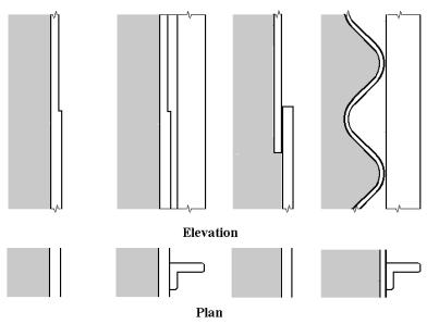
5.2 Distinctions between cylindrical shell forms
(1)For a shell wall constructed from flat rolled steel sheet, termed 'isotropic' (see figure 5.1), the resistances should be determined as defined in 5.3.2.
(2)For a shell wall constructed from corrugated steel sheets where the troughs run around the silo circumference, termed 'horizontally corrugated' (see figure 5.1), the resistances should be determined as defined in 5.3.4. For a shell wall with the troughs running up the meridian, termed 'vertically corrugated', the resistances should be determined as defined in 5.3.5.
28
EN 1993-4-1:2007 (Е)
(3)For a shell wall with stiffeners attached to the outside, termed 'externally stiffened' irrespective of the spacing of the stiffeners, the resistances should be determined as defined in 5.3.3.
(4)For a shell wall with lap joints formed by connecting adjacent plates with overlapping sections, termed 'lap-jointed' (see figure 5.1), the resistances should be determined as defined in 5.3.2.
Isotropic, externally stiffened, lap-jointed and horizontally corrugated walls
Figure 5.1: Illustrations of cylindrical shell forms
5.3 Resistance of silo cylindrical walls
5.3.1General
(1) The cylindrical shell should satisfy the provisions of EN 1993-1-6. These may be met using the following assessments of the design resistance.
5.3.2Isotropic welded or bolted walls
5.3.2.1General
(1)The shell wall cross-section should be proportioned to resist failure by rupture or plastic collapse.
(2)The joints should be proportioned to resist rupture on the net section using the ultimate tensile strength.
(3)The eccentricity of lap joints should be included in the strength assessment for rupture, when relevant.
(4)The shell wall should be proportioned to resist stability failure.
5.3.2.2Evaluation of design stress resultants
(1) Under internal pressure, frictional traction and all relevant design loads, the design stress resultants should be determined at every point in the shell using the variation in internal pressure and wall frictional traction, as appropriate.
29
EN 1993-4-1:2007 (Е)
NOTE 1: Each set of design stress resultants for stored solid loading of a silo should be based on a single set of stored solid properties.
NOTE 2: Where the design stress resultants are being evaluated to verify adequate resistance to the plastic limit state, in general the stored solid properties should be chosen to maximise the internal pressure and the condition of discharge with patch loads in EN 1991-4 should be chosen.
NOTE 3: Where the design stress resultants are being evaluated to verify adequate resistance to the buckling limit state under stored solid loads, in general the stored material properties should be chosen to maximise the axial compression and the condition of discharge with patch loads in EN 1991-4 should be chosen. However, where the internal pressure is beneficial in increasing the buckling resistance, only the filling pressures (for a consistent set of material properties) should be adopted in conjunction with the discharge axial forces, since the beneficial pressures may fall to the filling values locally even though the axial compression derives from the discharge condition.
(2)Where membrane theory is used to evaluate design stresses in the shell wall, the resistance of the shell should be adequate to withstand the highest pressure at every point.
(3)Because highly localised pressures are found to induce smaller design membrane stress resultants than would be found using membrane theory, the provisions of EN 1993-1-6 for stress design, direct design or computer design may be used to achieve a more economical design solution.
(4)Where a membrane theory analysis is used, the resulting two dimensional stress field of stress
resultants nx,Ed, nθ,Ed |
and nxθ,Ed |
|
may be evaluated using the equivalent design stress: |
|
||||||||||
σ |
|
= |
1 |
|
n 2 |
+ n |
2 |
|
− n |
|
n |
|
+ 3n 2 |
... (5.1) |
e,Ed |
|
|
|
x,Ed |
θ,Ed |
|||||||||
|
|
t |
x,Ed |
θ,Ed |
|
|
xθθEd |
|
||||||
|
|
|
|
|
|
|
|
|
|
|
|
|
||
(5)Where an elastic bending theory analysis (LA) is used, the resulting two dimensional stress
field of primary stress resultants |
nx,Ed, |
nθ,Ed, nxθ,Ed, mx,Ed, |
mθ,Ed, mxθ,Ed |
may be transformed into |
||||||||||||||||||
the fictitious stress components: |
|
|
|
|
|
|
|
|
|
|
|
|
|
|||||||||
σ |
|
= |
nx,Ed |
± |
mx,Ed |
|
, σ |
|
= |
nθ ,Ed |
± |
mθ ,Ed |
, |
... (5.2) |
||||||||
x,Ed |
|
|
|
θ ,Ed |
|
|
||||||||||||||||
|
|
|
|
t |
|
t |
2 |
/ 4 |
|
|
|
t |
|
t |
2 |
/ 4 |
|
|
||||
|
|
|
|
|
|
|
|
|
|
|
|
|
|
|
||||||||
τ |
|
|
= |
nxθ ,Ed |
± |
mxθ ,Ed |
, |
|
|
|
|
|
|
|
|
... (5.3) |
||||||
xθ ,Ed |
|
|
|
|
|
|
|
|
|
|
||||||||||||
|
|
|
t |
|
|
t |
2 |
/ 4 |
|
|
|
|
|
|
|
|
|
|
||||
|
|
|
|
|
|
|
|
|
|
|
|
|
|
|
|
|
|
|||||
and the von Mises equivalent design stress:
σe,Ed = σ2x.Ed + σθ2.Ed − σx.Edσθ.Ed + 3τ2xθ.Ed |
... (5.4) |
NOTE: The above expressions (Ilyushin yield criterion) give a simplified conservative equivalent stress for design purposes.
5.3.2.3Plastic limit state
(1)The design resistance in plates in terms of membrane stress resultants should be assessed as the
equivalent stress resistance for both welded and bolted construction |
fe,Rd given by: |
fe,Rd = fy / γM0 |
... (5.5) |
30

EN 1993-4-1:2007 (Е)
(2) The design resistance at lap joints in welded construction fe,Rd should be assessed by the fictitious strength criterion:
fe,Rd = j fy / γM0 |
... (5.6) |
where j is the joint efficiency factor.
(3) The joint efficiency of lap joint welded details with full continuous fillet welds should be taken as j = ji.
NOTE: The National Annex may choose the value of ji. The recommended values of ji are given in below for different joint configurations. The single welded lap joint should not be used if more than 20% of the value of σe,Ed in expression 5.4 derives from bending moments.
|
Joint efficiency ji of welded lap joints |
|
||
Joint type |
Sketch |
Value of ji |
||
Double |
welded |
|
j1 |
= 1,0 |
|
lap |
|
|
|
Single welded lap |
|
j2 |
= 0,35 |
|
(4) In bolted construction the design resistance at net section failure at the joint should be assessed in terms of membrane stress resultants as follows:
- |
for meridional resistance |
nx,Rd |
= |
fu |
t / γ M2 |
... (5.7) |
- |
for circumferential resistance |
nθ,Rd |
= |
fu |
t / γ M2 |
... (5.8) |
- |
for shear resistance |
nxθ,Rd |
= |
0.57 fy t / γ M0 |
... (5.9) |
|
(5)The design of bolted connections should be carried out in accordance with EN 1993-1-8 or EN 1993-1-3. The effect of fastener holes should be taken into account according to EN 1993-1-1 using the appropriate requirements for tension or compression or shear as appropriate.
(6)The resistance to local loads from attachments should be dealt with as detailed in 5.4.6.
(7)At every point in the structure the design stresses should satisfy the condition:
σe,Ed ≤ fe,Rd |
... (5.10) |
(8) At every joint in the structure the design stress resultants should satisfy the relevant conditions amongst:
nx,Ed ≤ nx,Rd |
... (5.11) |
31
|
|
|
EN 1993-4-1:2007 (Е) |
nθ,Ed |
≤ |
nθ,Rd |
... (5.12) |
nxθ,Ed |
≤ |
nxθ,Rd |
... (5.13) |
5.3.2.4Buckling under axial compression
(1)Under axial compression, the design resistance against buckling should be determined at every point in the shell using the prescribed fabrication tolerance quality of construction, the intensity of the guaranteed co-existent internal pressure, p and the circumferential uniformity of the compressive stress. The design should consider every point on the shell wall. In buckling calculations, compressive membrane forces should be treated as positive to avoid the widespread use of negative numbers.
(2)The prescribed fabrication tolerance quality of construction should be assessed as set out in table 5.1.
Table 5.1 Fabrication tolerance quality classes
Fabrication tolerance |
Quality |
Reliability class restrictions |
quality of construction |
parameter, Q |
|
|
|
|
Normal |
16 |
Compulsory when the silo is |
|
|
designed to Consequence Class 1 |
|
|
rules |
High |
25 |
|
Excellent |
40 |
Only permitted when the silo is |
|
|
designed to Consequence Class 3 |
|
|
rules |
NOTE: The tolerance requirements for the Fabrication Tolerance Consequence Quality Classes are set out in EN 1993-1-6 and EN 1090.
(3)The representative imperfection amplitude wok should be taken as:
w |
= |
t |
|
r |
|
|
|
|
|
... (5.14) |
||
|
|
|
|
|
|
|
|
|
||||
ok |
|
|
Q |
|
t |
|
|
|
|
|
|
|
|
|
|
|
|
|
|
|
|
|
|||
(4) The unpressurised elastic imperfection reduction factor |
αo should be found as: |
|||||||||||
α0 |
= |
|
|
0, 62 |
|
|
|
... (5.15) |
||||
|
|
|
|
|
|
|
|
|
|
|||
|
|
|
|
|
w |
1,44 |
|
|||||
|
|
|
|
|
|
|
|
|
||||
|
1 + 1, 91ψ |
|
|
ok |
|
|
||||||
|
|
|
|
|||||||||
|
|
|
|
|
|
|
|
t |
|
|
||
where the stress non-uniformity parameter ψ is unity in the case of circumferentially uniform compression, but is given in paragraph (8) for non-uniform compression.
(5) Where the silo is internally pressurised, the elastic imperfection reduction factor α should be taken as the smaller of the two following values: αpe and αpp, determined according to the local value of internal pressure p. For silos designed to Consequence Class 1 rules, the elastic imperfection factor α should not be taken as greater than α = αo.
32

EN 1993-4-1:2007 (Е)
(6)The elastic pressurised imperfection reduction factor αpe should be based on the smallest local
internal pressure (a value that can be guaranteed to be present) at the location of the point being assessed, and coexistent with the axial compression:
|
|
|
|
|
|
|
|
|
|
|
|
|
|
|
|
|
|
|
|
|
|
|
|
|
|
|
|
|
|
|
|
|
|
|
|
|
|
|
|
|
|
|
|
|
ps |
|
|
||||||
α |
|
= α |
|
+ (1 − α |
|
) |
|
|
|
|
|
|
|
... (5.16) |
|||
pe |
0 |
0 |
|
|
|
|
|
|
|
|
|
||||||
|
|
|
|
|
|
|
|
|
|
0, 3 |
|
|
|
||||
|
|
|
|
|
|
|
p |
s |
+ |
|
|
|
|
|
|
||
|
|
|
|
|
|
|
|
α0 |
|
||||||||
|
|
|
|
|
|
|
|
|
|
|
|
|
|
|
|
||
with:
|
|
|
= |
|
ps r |
|
|
ps |
|
||||
|
|
|
... (5.17) |
|||
|
|
|
||||
|
|
|
|
tσ x,Rcr |
||
where: |
|
|
|
|
||
ps |
is |
the minimum reliable design value of local internal pressure (see EN 1991-4); |
||||
σx,Rcr |
is |
the elastic critical buckling stress (see expression 5.28). |
||||
(7)The plastic pressurised imperfection reduction factor αpp should be based on the largest local
internal pressure at the location of compression:
|
|
|
|
|
|
2 |
|
|
|
|
p |
|
1 |
|
|||||
|
|
s |
|
|
|
||||
|
|
|
|
|
|
|
|
|
|
α pp |
= 1 − |
|
2 |
|
|
1 − |
|
3/ 2 |
|
|
|
|
λ x |
|
|
|
1,12 + s |
|
|
|
|
|
|
|
|
|
|
|
|
with:
the point being assessed, and coexistent |
with the axial |
|||||
s 2 |
+ 1,21 |
|
2x |
|
... (5.18) |
|
λ |
||||||
|
|
|
|
|
|
|
|
s(s + 1) |
|
||||
|
|
|
||||
|
|
|
|
|
|
|
|
|
|
|
= |
|
|
pg |
|
|
|
r |
|
|
|||
|
p |
g |
|
|
|
|
|
... (5.19) |
||||||||
|
|
|
|
|
|
|
|
|
|
|||||||
|
|
|
|
|
σ x,Rcr t |
|
|
|||||||||
|
|
|
|
|
|
|
|
|||||||||
|
|
|
|
|
1 |
|
r |
|
|
|||||||
s = |
|
|
|
|
|
|
|
|
|
... (5.20) |
||||||
|
|
|
|
|
|
|
||||||||||
|
|
|
|
400 |
t |
|
|
|||||||||
|
|
|
|
|
|
f y |
|
|
|
|
|
|
|
|
||
λ |
2 |
= |
|
|
|
|
|
|
|
|
|
... (5.21) |
||||
|
|
|
|
|
|
|
|
|
|
|
|
|||||
|
|
x |
|
|
σ x,Rcr |
|
|
|
|
|||||||
|
|
|
|
|
|
|
|
|
|
|||||||
where: |
|
|
|
|
|
|
|
|
|
|
|
|
|
|
||
pg |
|
is |
the largest design value of the local internal pressure (see EN 1991-4). |
|||||||||||||
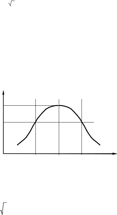
(8) Where the axial compression stress is non-uniform around the circumference, the effect should be represented by the stress non-uniformity parameter ψ, which should be determined from the linear elastic stress distribution of acting axial compressive stress distribution. The axial compressive membrane stress distribution around the circumference at the chosen level should be transformed as shown in figure 5.2. The design value of axial compressive membrane stress σx,Ed at the most highly stressed point at this axial coordinate is denoted as σxo,Ed.
33
EN 1993-4-1:2007 (Е)
The design value of axial compressive membrane stress at a second point, at the same axial coordinate, but separated from the first point by the circumferential distance
y = r Δθ = 4 rt |
... (5.22) |
should be taken as σx1,Ed.
(9)Where the stress ratio
|
σ x1,Ed |
|
|
|
s = |
|
... (5.23) |
||
|
||||
|
σ x 0,Ed |
|
|
|
|
|
|
lies in the range 0,3 < s < 1,0, the above location for the second point is satisfactory. Where the value of s lies outside this range, an alternative value of r θ should be chosen so that the value of s is found to be approximately s = 0,5. The following calculation should then proceed with a matched pair of values of s and θ.
σx,Ed
σxo,Ed
σx1,Ed
θo− θ |
θo |
θo+ θ |
θ |
Figure 5.2: Representation of local distribution of axial membrane stress resultant around the circumference
(10) The equivalent harmonic j of the stress distribution should be obtained as:
|
r |
|
σ x1,Ed |
|
|
|
j = 0, 25 |
arc cos |
|
... (5.24) |
|||
|
|
|||||
|
t |
|
|
|
|
|
|
|
σ x 0,Ed |
|
|||
and the stress non-uniformity parameter ψ should be determined as:
ψ = |
1 |
− b1 j |
||
|
|
|
... (5.25) |
|
|
|
|
||
|
1 + b2 j |
|||
with:
34

EN 1993-4-1:2007 (Е)
b1 = |
0,5 |
t |
|
... (5.26) |
||
|
|
|
||||
r |
|
|||||
|
|
|
|
|
||
b2 = |
|
(1 − b1 ) |
− 1 |
... (5.27) |
||
|
ψ b |
|||||
|
|
|
|
|||
where ψb is the value of stress non-uniformity parameter under global bending conditions.
NOTE: The National Annex may choose the value of ψb. The value ψb = 0,40 is recommended.
(11) The equivalent harmonic j at which imperfections cause no reduction below the uniform compression critical buckling resistance may be taken as j∞ = 1/b1. Where it is found that j > j∞, the value of j should be taken as j = j∞.
(12) Where a horizontal lap joint is used, causing eccentricity of the axial force in passing through the joint, the value of α given in paragraphs (4) to (7) above should be reduced to αL if the eccentricity of the middle surface of the plates to one another exceeds k1 t and the change in plate thickness at the joint is not more than k2 t, where t is the thickness of the thinner plate at the joint. Where the eccentricity is smaller than this value, or the change in plate thickness is greater, no reduction need be made in the value of α.
NOTE 1: The National Annex may choose the values of αL, k1 and k2. The values αL = 0,7α, k1 = 0,5 and k2 = 0,25 are recommended, where α is given by αo, αpe or αpp as appropriate.
NOTE 2: The buckling strength is only reduced below the value that would otherwise apply if the lower course is not thick enough to restrain the formation of a weaker buckle when an imperfection occurs immediately above the lap joint.
(13) The critical buckling stress of the isotropic wall should be calculated as:
σ x,Rcr |
= |
|
E |
|
|
t |
= 0, 605E |
t |
|
... (5.28) |
|
|
|
|
|
r |
|||||||
|
|
|
3(1 −ν 2 ) r |
|
|
||||||
(14) The characteristic buckling stress should be found, using the appropriate value of |
α from |
||||||||||
paragraphs (4), (5), (6), (7) and (8) above as: |
|
|
|
|
|||||||
σx,Rk |
= |
|
χx fy |
|
|
|
|
|
|
... (5.29) |
|
NOTE: |
The |
special |
convention using |
|
σRk and |
σRd for characteristic and design |
buckling |
||||
resistances follows that of prEN1993-1-6 for shell structures and differs from that detailed in EN1993-1-1.
(15) The buckling reduction factor χx should be determined as a function of the relative slenderness
of the shell λ¯ x from:
χx = 1 |
when |
λx ≤ λ0 |
... (5.30) |
35