

EN сталь / TKP EN 1993-4-1-2009
.pdfEN 1993-4-1:2007 (Е)
(2) The skirt should be checked for resistance to buckling under axial compression, including the effects of openings in the skirt.
8.5.2Column supported junctions and ring girders
(1)Where the silo is supported on discrete supports or columns, and a transition ring girder is used to distribute column forces into the shell, the junction and ring girder should satisfy the conditions given in 8.2.3 and 8.4.2.
(2)Where a transition ring girder is formed by bolting together an upper and lower half, each attached to a different shell segment, the bolts should be proportioned to resist transmission of the full design value of the circumferential force to be carried in the upper ring segment, taking proper account of bending actions in the ring.
8.5.3Base ring
(1)A silo that is continuously supported on the ground should be provided with a base ring and anchorage details.
(2)The circumferential spacing of anchorage bolts or other attachment points should not exceed 4 rt, where t is the local thickness of the shell plate.
(3)The base ring should have a flexural rigidity EIz about a vertical axis (to resist circumferential bending) greater than the minimum value EIz,min given by:
EIz,min = k Ert3 |
... (8.54) |
where t should be taken as the thickness of the wall strake adjacent to the base ring.
NOTE: The National Annex may choose the value of k. The value k = 0,10 is recommended.
86
EN 1993-4-1:2007 (Е)
9Design of rectangular and planar-sided silos
9.1 Basis
(1)A rectangular silo should be designed either as a stiffened box in which the structural action is predominantly bending, or as a thin membrane structure in which the action is predominantly membrane stresses developing after large deformations.
(2)Where the box is designed for bending action, the joints should be designed to ensure that the connectivity assumed in the stress analysis is achieved in the execution.
9.2 Classification of structural forms
9.2.1Unstiffened silos
(1)A structure formed from flat steel plates without attached stiffeners should be termed an 'unstiffened box'.
(2)A structure stiffened only along joints between plates which are not coplanar should also be termed an 'unstiffened box'.
9.2.2Stiffened silos
(1) A structure formed from flat plates to which stiffeners are attached within the plate area should be termed a 'stiffened box'. The stiffeners may be circumferential or vertical or orthogonal (two directional).
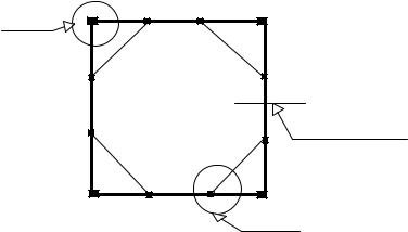
detail 1
vertical section
detail 2
Figure 9.1: Plan view of tied rectangular box silo
9.2.3Silos with ties
(1)Silos with ties may be square or rectangular.
NOTE: Some typical structural components for a 3-panel square (single cell) silo are shown in figures 9.1, 9.2 and 9.3.
87
EN 1993-4-1:2007 (Е)
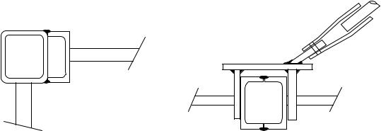
(DETAIL 2)
(DETAIL 1)
Figure 9.2: Typical details of tie connections
9.3 Resistance of unstiffened vertical walls
(1)The resistance of vertical walls should be evaluated in accordance with EN 1993-1-7. Alternatively, the provisions set out in 9.4 may be deemed to satisfy the provisions of that Standard.
(2)The resistance of vertical walls should be evaluated considering both the membrane and plate bending actions.
(3)The actions on the unstiffened plate may be divided into the following categories:
−bending as a 2D plate from the stored material;
−stresses resulting from diaphragm action;
−local bending action from the stored material and/or equipment.
9.4 Resistance of silo walls composed of stiffened and corrugated plates
9.4.1General
(1)The resistance of unstiffened parts of vertical walls should be evaluated in accordance with the provisions set out in 9.4. The resistance evaluation should consider both membrane and plate bending actions.
(2)Horizontally corrugated plates should be designed for:
−general bending action from pressures due to the stored material;
−stresses resulting from their diaphragm action;
−local bending action from the stored material and/or equipment.
(3)Effective bending properties and bending resistance of the stiffened plates should be derived in accordance with the provisions for trapezoidal sheeting with intermediate stiffeners in EN 1993-1-3.
(4)The design of the stiffeners should be made in accordance with member design given in EN1993-1-1 and EN1993-1-3, taking into account the compatibility of the stiffeners with the wall elements, the effect of the eccentricity of the sheeting in relation to the stiffener-axes, and the flexural continuities of wall elements and intersection horizontal and vertical stiffeners. Stresses normal to the longitudinal axis arising in stiffeners, which intersect structurally continuous wall-elements, should be taken into account additionally in the member design.
(5)The load transfer of vertical stiffeners to base boundary elements should be designed in accordance with the specific element and the given foundation resistance.
88
EN 1993-4-1:2007 (Е)
(6)Shear stiffness and resistance should be derived by testing or appropriate theoretical expressions.
(7)Unless a more precise method is available, the shear buckling strength may be assessed using 5.3.4.6 and treating the radius of the shell as infinite.
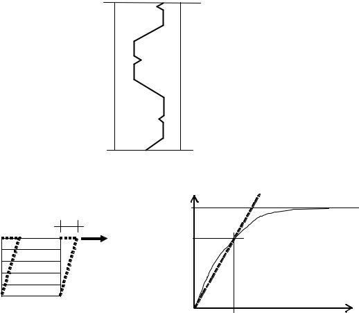
(8)Where testing is used, the relevant shear stiffness may be taken as the secant value achieved at 2/3 of the ultimate shear strength, see figure 9.4.
(vertical section)
Figure 9.3: Typical section on a vertical plane through the corrugated wall of rectangular silo
F |
Fu |
|
|
d |
|
F |
|
Fr = (2/3)Fu |
effective |
|
shear stiffness |
|
= Fr/dr |
|
dr |
|
d |
Figure 9.4: Shear response of corrugated wall
9.4.2General bending from direct action of the stored material
(1)Bending should be considered where horizontal bending can arise resulting from horizontal pressure or from horizontal pressure combined with wall friction.
(2)For bending from horizontal pressure alone, the calculation should be based on the effective properties as given by EN 1993-1-3.
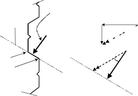
(3)For bending arising from horizontal pressure combined with wall friction, the calculation may be based on the concept outlined in figure 9.5, where the wall section between Point A and Point B is considered as a cross-section in bending under the action of the combined pressure pg. The stresses
arising from the moment should be combined with those from the axial force arising from the stored material pressure on the adjacent perpendicular walls (see 9.4.3).
89
EN 1993-4-1:2007 (Е)
NOTE: This calculation is conventional and well established. However, it may be noted that the continuity of strain between adjacent wall sections is neglected.
α |
Combined pressure p g normal to the plane AB |
|
|
A |
pn |
|
||
|
|
φw |
|
|
pw |
|
|
pc |
|
|
pg |
|
|
φw − α |
|
|
pc |
B
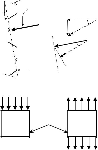
Figure 9.5: Bending resulting from combined horizontal pressure and friction (vertical section)
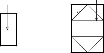
diaphragm action in these walls
wind action |
stored material pressures |
Figure 9.6: Membrane forces induced in walls by solids pressures or wind loading
9.4.3Membrane stresses from diaphragm action
(1)The stresses result from pressure of stored material and/or wind on the perpendicular neighbouring walls, see figure 9.6.
(2)As a simple rule, pressures from the stored material may be taken as only normal pressures (neglecting wall friction).
(3)Direct and shear stresses from wind action may be determined using either hand calculations or a finite element calculation.
90
EN 1993-4-1:2007 (Е)
9.4.4Local bending action from the stored material and/or equipment
(1) The possibility of deleterious local bending effects in any structural element due to the local stored material pressure should be taken into account.
NOTE: In the situation shown in figure 9.7, the structural check on the plate element CD may be critical.
Combined pressure p normal to the plane CD
g
pn
pw φw


δ 

 pc
pc
C |
pc |
δ − φw |
|
||
|
D |
pg |
|
|
Figure 9.7: Possible local bending actions
9.5 Silos with internal ties
9.5.1Forces in internal ties due to solids pressure on them
(1)The force exerted by the stored bulk solid on the tie should be evaluated.
(2)Unless more precise calculations are made, the force exerted by the solid qt per unit length of tie may be approximated by:
qt |
= Ct pv b |
... (9.1) |
||||
with: |
|
|
|
|
|
|
Ct |
= |
Cs |
β |
|
... (9.2) |
|
k L |
||||||
|
|
|
||||
where: |
|
|
|
|
|
|
pv |
is |
the vertical pressure within the stored material at the tie level; |
|
|||
b |
is |
the maximum horizontal width of the tie; |
|
|||
Ct |
is |
the load magnification factor; |
|
|||
Cs |
is |
the shape factor for the tie cross-section; |
|
|||
kL |
is |
the loading state factor; |
|
|||
β |
is |
the tie location factor, that depends on the position of the tie within the silo cell |
||||
|
|
|
(see figures 9.8 and 9.9). |
|
||
91
EN 1993-4-1:2007 (Е)
(3)The shape factor Cs should be taken as follows:
− |
for circular smooth sections : |
Cs |
= |
Csc |
− |
for round rough or square sections : |
Cs |
= |
Css |
NOTE: The National Annex may choose the values of Csc and Css. The values Csc = 1,0 and
Css = 1,2 are recommended.
−
(4)The loading state factor kL should be taken as follows:
− |
for bulk solids filling : |
kL |
= |
kLf |
− |
for bulk solids discharge : |
kL |
= |
kLe |
NOTE: The National Annex may choose the value of kL. The value kLf = 4,0 and kLe = 2,0 are recommended.
β = 1 |
0,7 |
0,9 |
|
|
Figure 9.8: Evaluation of factor β for internal ties
9.5.2Modelling of ties
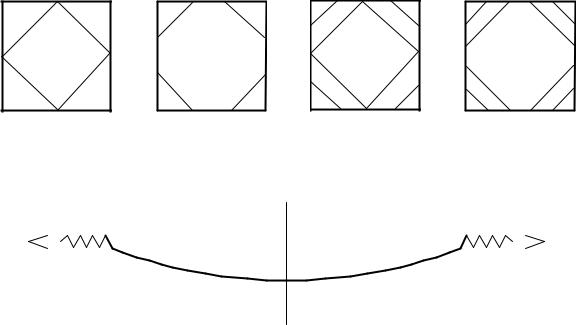
(1)Ties should be classified according to the principle means by which they support the loads. A tie should be classed as a cable if it has negligible bending stiffness. It should be classed as a rod if it has both axial stiffness and significant bending stiffness. The analysis of the tie should be appropriate to the structural response of the tie section.
(2)Where the tie is a rod, account should be taken of bending moments in addition to the axial tension.
(3)A geometrically non-linear calculation procedure should be used to determine the force N (and for rods, the moments M) in the tie. This analysis should take account of the real boundary conditions and the stiffness of the silo wall (Figure 9.10).
(4)The design values of axial tension N and moment M should be taken as the values in the tie at the connection to the wall.
(5)The initial sag of the tie should be agreed between the designer and/or the fabricator. For cables (negligible flexural stiffness), the initial sag should not be greater than ks L where L is the
length of the tie.
NOTE 1: The National Annex may choose the value of ks. The value ks = 0,01 is recommended.
92
EN 1993-4-1:2007 (Е)
NOTE 2: In past practice, the sag has often been set at 0,02L. The smaller value that is recommended here is needed to obtain a relationship between pressures and induced forces that is close linear in the operating range.
(6) The attachment details for ties should take account of both the vertical and the horizontal components of the tie tension at the point of attachment.
2 panels |
3 panels |
4 panels |
5 panels |
Figure 9.9: Corner ties for which β = 0,7
N |
k |
k |
N |
|
|
|
|
Figure 9.10: Force development in a tie
9.5.3Load cases for tie attachments
(1)The analysis of the tie should take account of:
−actions from the stored material;
−forces transmitted to the ties due to deformations of the walls from other load cases.
(2)Two load cases for the attachment forces and moments from a tie should be checked as follows:
a)load case 1: the values of qt and N evaluated in 9.5.1 and 9.5.2.
b)load case 2: an increased value of transverse load 1,2qt and a reduced value of tie tension 0,7N, where qt and N have been evaluated according to 9.5.1 and 9.5.2.
9.6Strength of pyramidal hoppers
(1)Pyramidal hoppers (Figure 9.12) should be treated as box structures, using the provisions of
EN 1993-1-7. These may be deemed to be met by the provisions of 9.3 and 9.4 for walls, together with the following approximate methods.
(2)The bending moments and membrane forces may be determined using numerical methods, in accordance with EN 1993-1-6 and EN 1993-1-7. The bending moments in the trapezoidal plates of the hopper may alternatively be evaluated using the following approximate relationships.
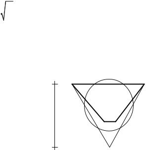
(3)An equilateral triangle ABE of area A should be drawn on the hopper plate ABCD, and the radius of the equivalent equal-area circle should be determined using:
93
EN 1993-4-1:2007 (Е)
|
= |
A |
|
|
|
||
req |
|
= 0,37 a |
... (9.3) |
||||
|
|||||||
|
|
π |
|
|
|
||
where: |
|
|
|
|
|
|
|
a |
is |
the horizontal length of the upper edge of the plate, see figure 9.11. |
|||||
|
|
|
|
|
a |
||
|
|
|
|
|
|
|
|
|
|
|
|
A |
|
|
B |
|
|
|
|
|
|
||
a.sin(60°)
C D
E
Figure 9.11: Simple model for bending of trapezoidal plates
(4)The reference bending moment M0 should be determined using:
M |
|
= |
|
3 |
p r2 |
= 0,026 p |
|
a2 |
... (9.4) |
0 |
|
|
n |
||||||
|
|
16 |
n eq |
|
|
|
|||
|
|
|
|
|
|
|
|
||
where: |
|
|
|
|
|
|
|
|
|
pn |
|
is |
|
the mean normal pressure on the trapezoidal plate. |
|
||||
(5) Where the trapezoidal plate has edges that may be treated as simply supported, the design value of bending moment may be taken as:
Ms,Ed = M0 |
... (9.5) |
(6) Where the trapezoidal plate has edges that may be treated as clamped, the bending moment at
the plate centre Ms,Ed |
and the bending moment at the edge Me,Ed |
may be taken as: |
|
Ms,Ed |
= |
0,80 M0 |
... (9.6) |
Me,Ed |
= |
0,53 M0 |
... (9.7) |
94
EN 1993-4-1:2007 (Е)
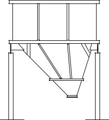
Figure 9.12: Unsymmetrical hopper with inclined ribs
9.7 Vertical stiffeners on box walls
(1)Vertical stiffeners on the walls of a box should be designed for:
−the permanent actions;
−the normal pressures on the wall due to bulk solids;
−the friction forces on the wall;
−the variable actions from the roof;
−the axial forces arising from contributions from the diaphragm action in the walls.
(2)The eccentricity of the friction forces from the plate and stiffener centrelines may be neglected.
9.8 Serviceability limit states
9.8.1Basis
(1)The serviceability limit states for rectangular silo walls should be taken as follows:
−deformations or deflections that adversely affect the effective use of the structure;
−deformations, deflections, vibration or oscillation that causes damage to both structural and non-structural elements.
(2)Deformations, deflections and vibrations should be limited to meet the above criteria.
(3)Specific limiting values, appropriate to the intended use, should be agreed between the designer, the client and the relevant authority, taking account of the intended use and the nature of the solids to be stored.
9.8.2Deflections
(1)The limiting value for global lateral deflection should be taken as the lesser of:
δmax |
= |
k1 H |
... (9.8) |
δmax |
= |
k2 t |
... (9.9) |
where:
95