

EN сталь / TKP EN 1993-4-1-2009
.pdfEN 1993-4-1:2007 (Е)
H |
is |
the height of the structure measured from the foundation to the roof; |
t |
is |
the thickness of the thinnest plate in the wall. |
NOTE: The National Annex may choose the values of k1 and k2. The values k1 = 0,02 and k2 = 10 are recommended.
(2) The maximum deflection δmax within any panel section relative to its edges should be limited to:
δmax < k3 L |
... (9.10) |
where L is the shorter dimension of the rectangular plate.
NOTE: The National Annex may choose the value of k3. The value k3 = 0,05 is recommended.
96
EN 1993-4-1:2007 (Е)
Annex A: [Informative]
Simplified rules for circular silos in Consequence Class 1
For circular silos with cylindrical walls in Consequence Class 1, this simplified treatment permits a design based only on the ultimate limit state and with a restricted number of load cases being addressed.
A.1 Action combinations for Consequence Class 1
The following simplified action combinations may be considered for silos in Consequence Class 1:
−Filling
−Discharge
−Wind when empty
−Filling, combined with wind
A simplified treatment of wind loading is permitted.
A.2 Action effect assessment
(1) When designing to the expressions given in this annex, the membrane stresses should be increased by the factor kM to account for local bending effects.
NOTE: The National Annex may choose the value of kM. The value kM = 1,1 is recommended.
(2) When designing to the expressions given in this annex, the hopper and ring forces should be increased by the factor kh to account for unsymmetrical and ring bending effects.
NOTE: The National Annex may choose the value of kh. The value kh = 1,2 is recommended.
A.3 Ultimate limit state assessment
A.3.1 General
(1) The limited provisions given here permit a faster assessment of a design, but they are often more conservative than the more complete provisions of the standard.
A.3.2 Isotropic welded or bolted cylindrical walls
A.3.2.1 Plastic limit state
(1)Under internal pressure and all relevant design loads, the design resistance should be determined at every point using the variation in internal pressure, as appropriate, and the local strength to resist it.
(2)At every point in the structure the design membrane stress resultants nx,Ed and nθ,Ed (both taken as tension positive) should satisfy the condition:
n2 |
− n |
x ,Ed |
n |
+ n2 |
,Ed |
≤ |
t f |
y |
/ γ |
M0 |
... (A.1) |
x,Ed |
|
θ ,Ed |
θ |
|
|
|
|
||||
where: |
|
|
|
|
|
|
|
|
|
|
|
nx,Ed is |
the vertical membrane stress resultant (force per unit width of shell wall) |
||||||||||
|
derived by analysis from the design values of the actions (loads); |
|
|||||||||
97
|
|
EN 1993-4-1:2007 (Е) |
nθ,Ed |
is |
the circumferential membrane stress resultant (force per unit width of shell |
|
|
wall) derived by analysis from the design values of the actions (loads); |
fy |
is |
the yield strength of the shell wall plate; |
γM0 |
is |
the partial factor against the plastic limit state. |
(3) At every bolted joint in the structure the design stress resultants should satisfy the conditions against net section failure:
- |
for meridional resistance |
nx,Ed |
≤ |
fu t / γM2 |
... (A.2) |
|
- |
for circumferential resistance |
nθ,Ed |
≤ |
fu t / γM2 |
... (A.3) |
|
where: |
|
|
|
|
|
|
fu |
is |
the ultimate strength of the shell wall plate; |
|
|||
γM2 |
is |
the partial factor against rupture (=1,25). |
|
|||
(4)The design of connections should be carried out in accordance with EN 1993-1-8 or EN 1993-1-
3. The effect of fastener holes should be taken into account according to EN 1993-1-1 using the appropriate requirements for tension or compression or shear as appropriate.
(5) The design resistance at lap joints in welded construction fe,Rd is given by the fictitious strength criterion:
fe,Rd = j fy / γM0 |
... (A.4) |
where j is the joint efficiency factor.
(6) The joint efficiency of lap joint welded details with full continuous fillet welds should be taken as j = ji.
NOTE: The National Annex may choose the value of ji. The recommended values of ji are given below for different joint configurations.
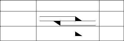
Joint efficiency ji of welded lap joints
Joint type |
Sketch |
Value of ji |
Double |
welded |
j1 = 1,0 |
lap |
|
|
Single welded lap |
|
|
|
j2 = 0,35 |
|
|
|
|
|
A.3.2.2 Axial compression
(1) Under axial compression, the design resistance should be determined at every point in the shell. The design should ignore the vertical variation of the axial compression, except where the provisions of EN 1993-1-6 make provision for this. In buckling calculations, compressive membrane forces should be treated as positive to avoid widespread use of negative numbers.
(2) Where a horizontal lap joint is used, causing eccentricity of the axial force in passing through the joint, the value of α given below should be reduced to 70% of its previous value if the eccentricity of the middle surface of the plates to one another exceeds t/2 and the change in plate
98
EN 1993-4-1:2007 (Е)
thickness at the joint is not more than t/4, where t is the thickness of the thinner plate at the joint. Where the eccentricity is smaller than this value, or the change in plate thickness is greater, no reduction need be made in the value of α.
(3)The elastic imperfection reduction factor α should be found as:
|
α = |
|
0, 62 |
|
|
|
|
|
... (A.5) |
|
|
|
|
|
|
|
|
||
|
|
r 0,72 |
|||||||
|
|
|
|
||||||
|
1 + 0, 035 |
|
|
|
|
||||
|
|
|
|
||||||
|
|
|
t |
|
|||||
where: |
|
|
|
|
|
|
|
|
|
r |
is |
the radius of the silo wall; |
|||||||
t |
is |
the thickness of the wall plate at the location being calculated. |
|||||||
(4) The critical buckling stress σx,Rcr |
at any point in the isotropic wall should be calculated as: |
||||||||
|
σ x ,Rcr |
= 0, 605E |
t |
|
... (A.6) |
||||
|
r |
||||||||
|
|
|
|
|
|
||||
(5)The characteristic buckling stress should be found as:
σx,Rk = χx fy |
... (A.7) |
in which:
χx = 1 |
|
|
|
|
|
|
|
|
|
|
|
|
− |
|
|
− |
|
|
||||||
|
|
|
|
|
|
|
|
|
|
|
when |
λx |
≤ λ0 |
|
... (A.8) |
|||||||||
|
|
|
|
|
|
|
|
|
|
|
|
|
|
|
|
|
|
|
|
|
|
|
|
|
|
|
λ |
x |
− λ |
|
|
|
|
|
|
|
|
|
|
|
|
||||||||
|
|
|
|
|
|
|
|
|
|
|
|
|
|
|||||||||||
χ |
= 1 |
|
− 0,6 |
|
|
0 |
|
when |
λ < λ < λ |
|
... (A.9) |
|||||||||||||
|
|
|
|
|
|
|
||||||||||||||||||
x |
|
|
|
|
|
λ |
|
− λ |
|
|
0 |
|
|
x |
p |
|
||||||||
|
|
|
|
|
|
|
|
|
0 |
|
|
|
|
|||||||||||
|
|
|
|
|
|
|
p |
|
|
|
|
|
|
|
|
|
|
|
|
|
||||
|
|
|
α |
|
|
|
|
|
|
|
|
|
|
|
|
|
|
|
|
|
|
|
||
χx |
= |
|
|
|
|
|
|
|
|
when |
λp |
≤ λx |
|
... (A.10) |
||||||||||
|
|
|
|
|
|
|
|
|
|
|||||||||||||||
|
|
2 |
|
|
|
|
|
|
|
|
|
|||||||||||||
λ |
|
|
|
|
|
|
|
|
|
|||||||||||||||
|
|
|
x |
|
|
|
|
|
|
|
|
|
|
|
|
|
|
|
|
|
|
|
||
with:
λ = |
f y |
, |
λ |
= 0, 2 and λ |
= 2,5α |
|
σx,Rc
(6)At every point in the structure the design membrane stress resultant nx,Ed (compression positive) should satisfy the condition: p0x
nx,Ed ≤ t σx,Rk / γM1 |
... (A.11) |
where γM1 is given by 2.9.2.
NOTE: The National Annex may choose the value of γM1. The value γM1 = 1,1 is recommended.
99

EN 1993-4-1:2007 (Е)
(7) The maximum permitted measurable imperfection, using the procedures of EN 1993-1-6 and excluding measurements across lap joints, should be found as:
wod = 0,0375 rt |
... (A.12) |
(8) The design of the shell against buckling under axial compression above a local support, near a bracket (e.g. to support a conveyor gantry), and near an opening should be undertaken as stipulated in 5.6.
A.3.2.3 External pressure, internal partial vacuum and wind
(1)For uniform partial internal vacuum (external pressure), where there is a structurally connected
roof, the critical buckling external pressure pnRcu for the isotropic wall should be found as:
|
|
r t 2,5 |
|
||||
|
pn ,Rcru |
= 0, 92E |
|
|
|
|
... (A.13) |
|
|
|
|||||
|
|
l r |
|
||||
where: |
|
|
|
|
|
|
|
r |
is |
the radius of the silo wall; |
|
||||
t |
is |
the thickness of the thinnest part of the wall; |
|
||||
l |
is |
the height between stiffening rings or boundaries. |
|
||||
(2) The design value of the maximum external pressure pn,Ed acting on the structure under the combined actions of wind and partial vacuum should satisfy the condition:
pn,Ed ≤ |
αn pn,Rcru / γM1 |
... (A.14) |
NOTE: |
The National Annex may choose the values of αn and γM1. |
The values αn = 0,5 and |
γM1 = 1,1 are recommended. |
|
|
(3) If the upper edge of the cylinder is not connected to the roof, this simple procedure should be replaced with that of 5.3.
A.3.3 Conical welded hoppers
(1)A simple design procedure may be used provided that both the following conditions are met:
a)An enhanced partial factor is used for the hopper of γM0 = γM0g;
b)No local meridional stiffeners or supports are attached to the hopper wall near the transition junction.
NOTE: The National Annex may choose the value of γM0g. The value γM0g = 1,4 is recommended.
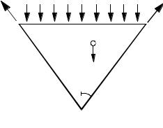
(2) Where the only loading under consideration is gravity and flow loading from the stored solid, the meridional force per unit circumference nφh,Ed,s caused by the symmetrical pressures defined in EN 1991-4 that must be transmitted through the transition joint should be evaluated using global equilibrium, see Figure A.1. The design value of the local meridional force per unit circumference nφh,Ed, allowing for the possible non-uniformity of the loading, should then be obtained as
nφh,Ed = gasym nφh,Ed,s |
… (A.15) |
100
EN 1993-4-1:2007 (Е)
where:
nφh,Ed,s
gasym
NOTE:
is |
the |
design value of the meridional membrane force per unit circumference at |
|
the |
top of the hopper obtained assuming the hopper loads are entirely |
|
symmetrical; |
|
is |
the unsymmetrical stress augmentation factor. |
|
Expressions for nφh,Ed,s may be found in Annex B. The National Annex may choose the
value of gasym. The value gasym = 1,2 is recommended.
Meridional |
Pressure from |
|
tension nφh |
cylinder contents |
|
|
Stored |
|
|
solids |
W |
 β
β
Figure A.1: Hopper global equilibrium
(3) |
The design value of the meridional membrane tension at the hopper top |
nφh,Ed should satisfy |
||
the condition: |
|
|
|
|
|
nφh,Ed |
≤ kr t fu / γM2 |
... (A.16) |
|
where: |
|
|
|
|
|
t |
is |
the thickness of the hopper; |
|
|
fu |
is |
the tensile strength; |
|
|
γM2 |
is |
the partial factor for rupture. |
|
NOTE: The National Annex may choose the value of kr. The value kr = 0,90 is recommended. The National Annex may also choose the value of γM2. The value γM2 = 1,25 is recommended.
A.3.4 Transition junction
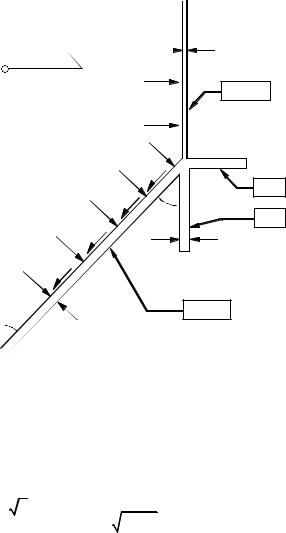
(1) This simplified design method may be used on silos of Consequence Class 1 where the junction consists of a cylindrical and conical section, with or without an annular plate or similarly compact ring at the junction, see figure A.2.
101
EN 1993-4-1:2007 (Е)
|
r |
tc |
|
|
|
|
pnc |
Cylinder |
|
|
|
|
|
Ap |
|
pnh |
|
|
|
Ring |
|
β |
Skirt |
|
µpn |
ts |
|
|
|
β |
th |
Hopper |
Figure A.2: Notation for simple transition junction
(2)The total effective area of the ring Aet should be found from:
|
|
|
|
|
t |
3 / 2 |
|
|
|
|
|
|
|
h |
|
|
|
A |
= A |
+ 0, 4 |
r t3 / 2 |
+ t3 / 2 + |
|
|
... (A.17) |
|
|
|
|||||||
et |
p |
|
c |
s |
cos β |
|
|
|
|
|
|
|
|
|
|
|
|
where: |
|
|
|
|
|
|
|
|
r |
is |
the radius of the silo cylinder wall; |
|
|||||
tc |
is |
the thickness of the cylinder; |
|
|
||||
ts |
is |
the thickness of the skirt; |
|
|
|
|||
th |
is |
the thickness of the hopper; |
|
|
||||
β |
is |
the cone apex half angle of the hopper; |
|
|||||
Ap |
is |
the area of the ring at the junction. |
|
|||||
(3) |
The design value of the circumferential compressive force |
Nθ,Ed developed in the junction |
should be determined from: |
|
|
|
Nθ,Ed = nφh,Ed r sinβ |
... (A.18) |
where: |
|
|
nφh,Ed is the design value of the meridional tension per unit circumference at the top of the hopper, see Figure A.1 and expression A.15.
102

EN 1993-4-1:2007 (Е)
(4)The mean circumferential stress in the ring should satisfy the condition:
Nθ ,Ed
Aet
where:
fy is
γM0 is
≤ |
f y |
... (A.19) |
|
γ M 0
the lowest yield strength of the ring and shell materials; the partial factor for plasticity.
NOTE: The National Annex may choose the value of γM0. The value γM0 = 1,0 is recommended.
103
EN 1993-4-1:2007 (Е)
Annex B: [Informative]
Expressions for membrane stresses in conical hoppers
The expressions given here permit membrane theory stress analyses to be undertaken for cases which are not obtainable in standard texts on shells or silo structures. Membrane theory expressions accurately predict the membrane stresses in the body of the hopper (i.e. at points not adjacent to the transition or support) provided that the applied loadings are according to patterns defined in EN 1991- 4.
Coordinate system with origin for z at the apex
Vertical height of hopper h and cone apex half angle β
B.1 Uniform pressure po with wall friction po
|
|
|
p z tan β |
|
|
||||
σθ |
= |
|
0 |
|
|
|
|
... (B.1) |
|
|
|
|
|||||||
|
|
|
t |
cos β |
|
|
|||
|
|
|
p z tan β + µ |
|
|||||
σφ |
= |
|
0 |
|
|
|
|
|
... (B.2) |
|
|
|
cos β |
||||||
|
|
|
2t |
|
|
|
|||
B.2 Linearly varying pressure from p1 at apex to p2 at transition with wall friction p
p = p + |
z |
|
( p |
|
− p ) |
|
|
|
|
||||
|
2 |
|
|
|
|
||||||||
|
1 |
h |
|
|
|
|
1 |
|
|
|
|
||
|
|
|
|
|
|
|
|
|
|
|
|
||
|
|
|
|
|
z |
|
|
|
z tan β |
||||
σθ |
= p1 |
+ |
|
|
( p2 |
− p1 ) |
|
|
|
|
|||
|
h |
|
|
||||||||||
|
|
|
|
|
|
|
|
t cos β |
|||||
|
|
|
2z |
|
|
z tan β + µ |
|||
σφ |
= 3 p1 |
+ |
|
( p2 |
− p1 ) |
|
|
|
|
h |
|
cos β |
|||||||
|
|
|
|
|
6t |
|
|||
For = 0, the maximum von Mises equivalent stress occurs in the body of the cone if
at the height:
|
p1 |
|
|
z = 0,52 |
h |
||
|
|||
|
p2 − p1 |
||
... (B.3)
... (B.4)
... (B.5)
p2 < 0,48 p1
... (B.6)
B.3 “Radial stress field” with triangular switch stress at the transition
p = p1 |
z |
for 0 < z < h1 |
... (B.7) |
|
|||
h |
|||
1 |
|
|
|
104
EN 1993-4-1:2007 (Е)
p = |
p1 (h − z ) − p2 (h1 − z ) |
|
|
|
|
|
|
for h1 < z < h |
||||||||||||||
|
|
|
|
|
|
|
h − h1 |
|
|
|
|
|
|
|
||||||||
|
|
|
|
|
|
|
|
|
|
|
|
|
|
|
|
|
|
|
||||
|
|
|
|
|
|
|
|
z2 |
tan β |
|
|
|
|
|
|
|
|
|
|
|||
σθ |
= p1 |
|
|
|
|
|
|
|
|
|
|
|
|
|
for 0 < z < h1 |
|||||||
|
|
|
|
|
|
|
|
|
|
|
||||||||||||
|
|
|
|
|
|
|
3ht |
cos β |
|
|
|
|
|
|
|
|
|
|
||||
|
|
|
zp (h − z) − p |
(h − z) tan |
β |
|
|
|
|
|||||||||||||
σθ |
= |
|
1 |
|
|
|
2 |
1 |
|
|
|
|
|
|
for h1 < z < h |
|||||||
|
|
|
|
|
|
t(h − h1 ) |
|
|
|
|
||||||||||||
|
|
|
|
|
|
|
|
|
|
|
cos |
β |
|
|
|
|
||||||
|
|
|
p z |
2 tan β + µ |
|
|
|
|
|
|
|
|
|
|
||||||||
σφ |
= |
|
|
1 |
|
|
|
|
|
|
|
|
|
|
|
|
|
|
for 0 < z < h1 |
|||
|
|
|
|
|
|
|
cos β |
|
|
|
|
|
|
|||||||||
|
|
|
3th1 |
|
|
|
|
|
|
|
|
|
|
|
||||||||
|
|
|
|
2z3 ( p |
2 |
− p ) + (3z2 − h2 )(hp − h p ) tan β + µ |
|
|||||||||||||||
σφ |
= |
|
|
|
|
|
|
1 |
|
1 |
1 |
1 |
2 |
|
|
for h1 |
||||||
|
|
|
|
|
|
|
|
6zt(h − h1 ) |
|
|
|
|
|
|||||||||
|
|
|
|
|
|
|
|
|
|
|
|
|
|
|
cos β |
|
||||||
... (B.8)
... (B.9)
... (B.10)
... (B.11)
< z < h
|
|
|
... (B.12) |
in which p1 is the pressure at a height h1 above the apex and p2 is the pressure at the transition. |
|||
B.4 |
General hopper theory pressures |
|
|
The pressure pattern may be defined in terms of the normal pressure p |
with accompanying wall |
||
frictional traction |
µp as: |
|
|
|
p = |
Fq |
... (B.13) |
|
γ h |
z |
z n |
z n |
|
|||||||
q = |
|
|
|
|
− |
|
|
|
+ qt |
|
|
... (B.14) |
|
|
|
|
|||||||||
|
n − 1 h |
h |
|
h |
|
|||||||
|
|
|
|
|
|
|
|
|
|
|
||
with: |
|
|
|
|
|
|
|
|
|
|
|
|
|
|
|
|
|
|
|
|
|
|
|
|
|
|
|
|
|
|
|
|
|
|
|
|
|
|
|
n = 2(Fµ cotβ + F − 1) |
|
|
|
|
|
|
|
|
|
|
|
|
|
|
|
|
|
|
|
|
|
|
|
|
... (B.15) |
||||||||||||||
F is the ratio of wall pressure |
p to vertical stress in the solid |
q and |
qt is the mean vertical stress in |
||||||||||||||||||||||||||||||||||||
the solid at the transition: |
|
|
|
|
|
|
|
|
|
|
|
|
|
|
|
|
|
|
|
|
|
|
|
|
|
|
|
|
|
|
|
|
|
|
|
||||
|
|
γ h |
z |
2 |
|
|
|
|
γ h |
|
z |
n+1 |
|
|
Fh |
tan β |
|
|
|
|
|
||||||||||||||||||
σ θ |
= |
|
|
|
|
|
|
|
|
|
|
|
... (B.16) |
||||||||||||||||||||||||||
|
|
|
|
|
|
|
+ |
q t − |
|
|
|
|
|
|
|
|
|
|
|
|
|
|
|
|
|
|
|
|
|
|
|||||||||
|
|
|
|
|
|
|
|
|
|
|
|
|
|
|
|
|
|
|
|
||||||||||||||||||||
|
(n − 1) |
h |
|
|
|
|
|
(n − 1) |
h |
|
|
|
|
t |
cos β |
|
|
|
|
|
|||||||||||||||||||
|
|
|
|
|
|
|
|
|
|
|
|
|
|
|
|
|
|
|
|
|
|
|
|
|
|
|
|
|
|
|
|
|
|
|
|
|
|
|
|
|
|
γ h |
|
z |
|
2 |
|
1 |
|
|
|
|
|
|
γ h |
z |
n+1 |
|
|
Fh |
tan β + µ |
|
|||||||||||||||||
σ φ |
= |
|
|
+ |
|
|
− |
|
|
|
|
|
... (B.17) |
||||||||||||||||||||||||||
|
|
|
|
|
|
|
|
|
|
|
q t |
|
|
|
|
|
|
|
|
|
|
|
|
|
|
|
|
|
|
||||||||||
|
|
|
|
|
(n + |
|
|
|
|
|
|
|
|
|
|
|
|
|
cos β |
||||||||||||||||||||
|
3(n − 1) h |
|
|
|
2) |
|
|
(n − 1) h |
|
|
|
|
t |
|
|
|
|||||||||||||||||||||||
|
|
|
|
|
|
|
|
|
|
|
|
|
|
|
|
|
|
|
|
|
|
|
|
|
|
|
|
|
|
|
|
|
|
|
|
|
|
|
|
105