

EN сталь / TKP EN 1993-4-1-2009
.pdfТЕХНИЧЕСКИЙ КОДЕКС |
ТКП EN 1993-4-1-2009 (02250) |
УСТАНОВИВШЕЙСЯ ПРАКТИКИ |
|
Еврокод 3 ПРОЕКТИРОВАНИЕ СТАЛЬНЫХ КОНСТРУКЦИЙ Часть 4-1. Бункеры
Еўракод 3 ПРАЕКТАВАННЕ СТАЛЬНЫХ КАНСТРУКЦЫЙ Частка 4-1. Бункеры
(EN 1993-4-1:2007, IDT)
Издание официальное
Министерство архитектуры и строительства Республики Беларусь Минск 2010
Издание официальное

ТКП EN 1993-4-1-2009
УДК 624.95.014.2.04(083.74) МКС 65.040.20; 91.010.30; 91.080.10 КП 02 IDT
Ключевые слова: моделирование бункера, конструкционные стали, нержавеющие стали, специальные легированные стали, прямоугольный бункер, сопротивление конструкций
Предисловие
Цели, основные принципы, положения по государственному регулированию и управлению в области технического нормирования и стандартизации установлены Законом Республики Беларусь «О техническом нормировании и стандартизации».
1 ПОДГОТОВЛЕН ПО УСКОРЕННОЙ ПРОЦЕДУРЕ научно-проектно-производственным республиканским унитарным предприятием «Стройтехнорм» (РУП «Стройтехнорм»)
ВНЕСЕН главным управлением научно-технической политики и лицензирования Министерства архитектуры и строительства Республики Беларусь
2 УТВЕРЖДЕН И ВВЕДЕН В ДЕЙСТВИЕ приказом Министерства архитектуры и строительства Республики Беларусь от 10 декабря 2009 г. № 405
ВНациональном комплексе технических нормативных правовых актов в области архитектуры
истроительства настоящий технический кодекс установившейся практики входит в блок 5.04 «Металлические конструкции и изделия»
3 Настоящий технический кодекс установившейся практики идентичен европейскому стандарту
EN 1993-4-1:2007 Eurocode 3: Design of steel structures — Part 4-1. Silos (Еврокод 3. Проектирование стальных конструкций. Часть 4-1. Бункеры).
Европейский стандарт разработан техническим комитетом по стандартизации CEN/TC 250 «Еврокоды конструкций».
Перевод с английского языка (еn).
Перевод изменения 1 с немецкого языка (de).
Официальные экземпляры европейского стандарта, на основе которого подготовлен настоящий технический кодекс установившейся практики, и европейских стандартов, на которые даны ссылки, имеются в Национальном фонде ТНПА.
Степень соответствия — идентичная (IDT)
4 ВВЕДЕН ВПЕРВЫЕ
© Минстройархитектуры, 2010
Настоящий технический кодекс установившейся практики не может быть воспроизведен, тиражирован и распространен в качестве официального издания без разрешения Министерства архитектуры и строительства Республики Беларусь
ii
ТКП EN 1993-4-1-2009
Издан на русском языке
|
Содержание |
|
Введение.................................................................................................................................................... |
|
v |
Европейский стандарт EN 1993-4-1:2007 на английском языке........................................................... |
1 |
|
Изменение 1 к европейскому стандарту EN 1993-4-1:2007 на немецком языке............................. |
108 |
|
Приложение Д.А (справочное) Перевод европейского стандарта 1993-4-1:2007 |
|
|
|
на русский язык....................................................................................................... |
112 |
1 Общие положения..................................................................................................................... |
112 |
|
1.1 |
Область применения......................................................................................................... |
112 |
1.2 |
Нормативные ссылки........................................................................................................ |
113 |
1.3 |
Допущения ......................................................................................................................... |
113 |
1.4 |
Различие между принципами и правилами применения............................................... |
113 |
1.5 |
Термины и определения................................................................................................... |
114 |
1.6 |
Символы, используемые в части 4-1 Еврокода 3 .............................................................. |
116 |
1.7 |
Знаки условных обозначений........................................................................................... |
118 |
1.8 |
Единицы измерения.......................................................................................................... |
122 |
2 Основы проектирования............................................................................................................ |
122 |
|
2.1 |
Требования ........................................................................................................................ |
122 |
2.2 |
Разграничение надежности.............................................................................................. |
123 |
2.3 |
Предельные состояния..................................................................................................... |
124 |
2.4 |
Воздействия и экологические последствия.................................................................... |
124 |
2.5 |
Свойства материала......................................................................................................... |
124 |
2.6 |
Геометрические данные ................................................................................................... |
124 |
2.7 |
Моделирование бункера для определения последствий воздействия........................ |
124 |
2.8 |
Проектирование, сопровождаемое тестированием....................................................... |
125 |
2.9 |
Последствия воздействия для верификации предельного состояния......................... |
125 |
2.10 Долговечность ................................................................................................................. |
126 |
|
2.11 Огнеупорность................................................................................................................. |
126 |
|
3 Свойства материалов............................................................................................................... |
126 |
|
3.1 |
Общие положения............................................................................................................. |
126 |
3.2 |
Конструкционные стали.................................................................................................... |
126 |
3.3 |
Нержавеющие стали......................................................................................................... |
126 |
3.4 |
Специальные легированные стали.................................................................................. |
126 |
3.5 |
Требования к прочности ................................................................................................... |
126 |
4 Основа структурного анализа .................................................................................................. |
127 |
|
4.1 |
Крайние предельные состояния ...................................................................................... |
127 |
4.2 |
Анализ конструкции оболочкового бункера.................................................................... |
127 |
4.3 |
Анализ коробчатой конструкции прямоугольного бункера............................................ |
130 |
4.4 |
Эквивалентные ортотропные свойства обшивки из гофрированного листа ............... |
131 |
|
|
iii |
ТКП EN 1993-4-1-2009 |
|
|
5 Проектирование стенок цилиндра........................................................................................... |
132 |
|
5.1 |
Основа................................................................................................................................ |
132 |
5.2 |
Различия между формами цилиндрических оболочек .................................................. |
133 |
5.3 |
Сопротивление цилиндрических стенок бункера........................................................... |
133 |
5.4 |
Особые условия поддержки цилиндрических стенок..................................................... |
152 |
5.5 |
Детализация отверстий в цилиндрических стенках....................................................... |
155 |
5.6 |
Предельные эксплуатационные состояния .................................................................... |
156 |
6 Проектирование конических бункеров-хопперов ................................................................... |
157 |
|
6.1 |
Основа................................................................................................................................ |
157 |
6.2 |
Различия между формами оболочек бункера ................................................................ |
157 |
6.3 |
Сопротивление конических бункеров-хопперов............................................................. |
158 |
6.4 |
Рассмотрение специальных конструкций бункеров....................................................... |
162 |
6.5 |
Эксплуатационная пригодность предельных состояний............................................... |
163 |
7 Проектирование конструкций круглой конической крыши..................................................... |
163 |
|
7.1 |
Основа................................................................................................................................ |
163 |
7.2 |
Различия между формами конструкции крыши.............................................................. |
163 |
7.3 |
Сопротивление круглых конических крыш бункера........................................................ |
164 |
8 Проектирование переходных сочленений и поддерживающих кольцевых балок.............. |
164 |
|
8.1 |
Основа................................................................................................................................ |
164 |
8.2 |
Анализ сочленения............................................................................................................ |
166 |
8.3 |
Сопротивление конструкций............................................................................................. |
171 |
8.4 |
Верификация предельных состояний.............................................................................. |
175 |
8.5 |
Рассмотрение схем расположения опорных элементов сочленения .......................... |
177 |
9 Проектирование прямоугольных бункеров с плоскими боковыми стенками....................... |
177 |
|
9.1 |
Основа................................................................................................................................ |
177 |
9.2 |
Классификация конструкционных форм.......................................................................... |
177 |
9.3 |
Сопротивление вертикальных стенок без усиления...................................................... |
178 |
9.4 |
Сопротивление стенок бункера из гофрированных листов с усилением .................... |
179 |
9.5 |
Бункеры с внутренними стяжками ................................................................................... |
182 |
9.6 |
Прочность пирамидальных бункеров.............................................................................. |
183 |
9.7 |
Вертикальные ребра жесткости на коробчатых стенках................................................ |
184 |
9.8 |
Эксплуатационная пригодность предельных состояний............................................... |
185 |
Приложение А (справочное) Упрощенные правила |
|
|
|
для круглых бункеров последовательного класса 1....................................... |
186 |
Приложение В (справочное) Выражение мембранных напряжений |
|
|
|
в конических бункерах....................................................................................... |
191 |
Приложение С (справочное) Распределение давления ветра вокруг конструкций |
|
|
|
цилиндрического бункера.................................................................................. |
193 |
Приложение Д.Б (справочное) Перевод изменения 1 |
|
|
|
к европейскому стандарту EN 1993-4-1:2007 на русский язык...................... |
195 |
iv
ТКП EN 1993-4-1-2009
Введение
Настоящий технический кодекс установившейся практики разработан по ускоренной процедуре с целью обеспечения применения в Республике Беларусь европейских стандартов в области проектирования строительных конструкций (Еврокодов).
Текст европейского стандарта опубликован на языке оригинала. Перевод европейского стандарта на русский язык (с приложениями А, В, С) приведен в справочном приложении Д.А, а изменения 1 к нему — в справочном приложении Д.Б.
v
EN 1993-4-1:2007 (Е)
1General
1.1 Scope
(1)Part 4.1 of Eurocode 3 provides principles and application rules for the structural design of steel silos of circular or rectangular plan-form, being free standing or supported.
(2)The provisions given in this Part supplement modify or supersede the equivalent provisions given in EN 1993-1.
(3)This part is concerned only with the requirements for resistance and stability of steel silos. For other requirements (such as operational safety, functional performance, fabrication and erection, quality control, details like man-holes, flanges, filling devices, outlet gates and feeders etc.), see the relevant standards.
(4)Provisions relating to special requirements of seismic design are provided in EN 1998-4, which complements or adapts the provisions of Eurocode 3 specifically for this purpose.
(5)The design of supporting structures for the silo are dealt with in EN 1993-1-1. The supporting structure is deemed to consist of all structural elements beneath the bottom flange of the lowest ring of the silo, see figure 1.1.
(6)Foundations in reinforced concrete for steel silos are dealt with in EN 1992 and EN 1997.
(7)Numerical values of the specific actions on steel silos to be taken into account in the design are given in EN 1991-4 Actions in Silos and Tanks.
(8)This Part 4.1 does not cover:
−resistance to fire;
−silos with internal subdivisions and internal structures;
−silos with capacity less than 10 tonnes;
−cases where special measures are necessary to limit the consequences of accidents.
(9)Where this standard applies to circular planform silos, the geometric form is restricted to axisymmetric structures, but the actions on them may be unsymmetrical, and their supports may induce forces in the silo that are not axisymmetrical.
1.2 Normative references
This European Standard incorporates, by dated and undated reference, provisions from other standards. These normative references are cited at the appropriate places in the text and the publications are listed hereafter. For dated references, subsequent amendments to, or revisions of, any of these publications apply to the European Standard only when incorporated in it by amendment or revision. For undated references the latest edition of the publication referred to applies.
EN 1090 Execution of steel structures;
EN 1990 Eurocode: Basis of design;
EN 1991 Eurocode 1: Actions on structures;
Part 1.1 Actions on structures – Densities, self-weight and imposed loads for buildings;
Part 1.2: Actions on structures – Actions on structures exposed to fire;
Part 1.3: Actions on structures – Snow loads;
Part 1.4: Actions on structures – Wind loads;
1
EN 1993-4-1:2007 (Е)
Part 1.5: |
Actions on structures – Thermal loads; |
Part 1.6: |
Actions on structures – Construction loads; |
Part 1.5: |
Actions on structures – Accidental actions; |
Part 4: |
Actions on silos and tanks; |
EN 1993 |
Eurocode 3: Design of steel structures; |
Part 1.1: |
General rules and rules for buildings; |
Part 1.3: |
Cold formed thin gauge members and sheeting; |
Part 1.4: |
Stainless steels; |
Part 1.6: |
Strength and stability of shell structures; |
Part 1.7: |
Planar plated structures loaded transversely; |
Part 1.8: |
Design of joints; |
Part 1.9: |
Fatigue strength of steel structures; |
Part 1.10: |
Selection of steel for fracture toughness and through-thickness properties; |
Part 4.2: |
Tanks; |
EN 1997 |
Eurocode 7: Geotechnical design; |
EN 1998 |
Eurocode 8: Design provisions for earthquake resistance of structures; |
Part 4: |
Silos, tanks and pipelines; |
EN 10025 |
Hot rolled products of non-alloy structural steels - technical delivery |
|
conditions; |
EN 10147 |
Hot-rolled flat products made of high yield strength steels for cold forming; |
ISO 1000 |
SI Units; |
ISO 3898 |
Bases for design of structures - Notation - General symbols; |
ISO 4997 |
Cold reduced steel sheet of structural quality; |
ISO 8930 |
General principles on reliability for structures - List of equivalent terms. |
1.3 Assumptions
(1) In addition to the general assumptions of EN 1990 the following assumptions apply:
– fabrication and erection complies with EN 1090-2
1.4 Distinction between principles and application rules
(1)See 1.4 in EN 1990.
1.5 Terms and definitions
(1) The terms that are defined in 1.5 in EN 1990 for common use in the Structural Eurocodes and the definitions given in ISO 8930 apply to this Part 4.1 of EN 1993, unless otherwise stated, but for the purposes of this Part 4.1 the following supplementary definitions are given:
1.5.1 shell. A structure formed from a curved thin plate.
2
EN 1993-4-1:2007 (Е)
1.5.2axisymmetric shell. A shell structure whose geometry is defined by rotation of a meridional line about a central axis.
1.5.3box. A structure formed from an assembly of flat plates into a three-dimensional enclosed form. For the purposes of this Standard, the box has dimensions that are generally comparable in all directions.
1.5.4meridional direction. The tangent to the silo wall in a vertical plane at any point. It varies according to the structural element being considered. Alternatively, it is the vertical or inclined direction on the surface of the structure that a rain drop would take in sliding down the surface.
1.5.5circumferential direction. The horizontal tangent to the silo wall at any point. It varies around the silo, lies in the horizontal plane and is tangential to the silo wall irrespective of whether the silo is circular or rectangular in plan.
1.5.6middle surface. This term is used to refer to both the stress-free middle surface when a shell is in pure bending and the middle plane of a flat plate that forms part of a box.
1.5.7separation of stiffeners. The centre to centre distance between the longitudinal axes of two adjacent parallel stiffeners.
Supplementary to Part 1 of EN 1993 (and Part 4 of EN 1991), for the purposes of this Part 4.1, the following terminology applies, see figure 1.1:
1.5.8silo: A silo is a vessel for storing particulate granular solids. In this Standard, it is assumed to have a vertical form with solids being added by gravity at the top. The term silo includes all forms of particulate solids storage structure, that might otherwise be referred to as a bin, hopper, grain tank or bunker.
1.5.9barrel: The barrel is the vertical walled section of a silo.
1.5.10hopper: A hopper is a converging section towards the bottom of a silo. It is used to channel solids towards a gravity discharge outlet.
1.5.11junction: A junction is the point at which any two or more shell segments, or two or more flat plate elements of a box meet. It can include a stiffener or not: the point of attachment of a ring stiffener to the shell or box may be treated as a junction.
1.5.12transition junction: The transition junction is the junction between the barrel and hopper. The junction can be at the base of the barrel or part way down it.
1.5.13skirt: The skirt is that part of the barrel which lies below the transition junction: it differs from the higher part in that it has no contact with the stored bulk solids.
1.5.14strake: A strake or course is a single layer of steel plates used to form one level of the cylindrical barrel of a silo.
1.5.15stringer stiffener: A stringer stiffener is a local stiffening member that follows the meridian of a shell, representing a generator of the shell of revolution. It is provided to increase the stability, or to assist with the introduction of local loads or to carry axial loads. It is not intended to provide a primary load carrying capacity for bending due to transverse loads.
1.5.16rib: A rib is a local member that provides a primary load carrying path for loads causing bending down the meridian of a shell or flat plate, representing a generator of the shell of revolution
3
EN 1993-4-1:2007 (Е)
or a vertical stiffener on a box. It is used to distribute transverse loads on the structure by bending action.
1.5.17ring stiffener: A ring stiffener is a local stiffening member that passes around the circumference of the structure at a given point on the meridian. It is assumed to have no stiffness in the meridional plane of the structure. It is provided to increase the stability or to introduce local loads, not as a primary load-carrying element. In a shell of revolution it is circular, but in rectangular structures is takes the rectangular form of the plan section.
1.5.18smeared stiffeners: Stiffeners are said to be smeared when the properties of the shell wall and the individual stiffeners are treated as a composite section using a width equal to an integer multiple of the separation of the stiffeners. The stiffness properties of a shell wall with smeared stiffeners are orthotropic with eccentric terms leading to coupling between bending and stretching behaviour.
|
|
|
|
|
|
|
|
|
|
|
|
|
|
|
Conical roof |
|
|
|
|
|
|
|
|
|
|
|
|
|
|
|
Pyramidal |
|
|
|
||||||||
|
|
|
|
|
|
|
|
|
|
|
|
|
|
|
|
|
|
|
|
|||||||||||||||||||||||
|
|
|
|
|
|
|
|
|
|
|
|
|
|
|
|
|
|
|
|
|
|
|
|
|
|
|
|
|
|
|
|
|
|
roof |
|
|
|
|||||
|
|
|
|
|
|
|
|
|
|
|
|
|
|
|
|
|
|
|
|
|||||||||||||||||||||||
|
|
|
|
|
|
|
|
|
|
|
|
|
|
|
|
|
|
|
|
|
|
|
|
|
|
|
|
|
|
|
|
|
|
|
|
|
|
|
|
|
|
|
|
|
|
|
|
|
|
|
|
|
|
|
|
|
|
|
|
|
|
|
|
|
|
|
|
|
|
|
|
|
|
|
|
|
|
|
|
|
|
|
|
|
|
|
|
|
|
|
|
|
|
|
|
|
|
|
|
|
|
Cylindrical |
|
|
|
|
|
|
|
|
|
|
|
|
|
|
|
Rectangular |
|
|
||||||||
|
|
|
|
|
|
|
|
|
|
|
|
|
|
|
|
shell or |
|
|
|
|
|
|
|
|
|
|
|
|
|
|
|
box |
|
|
||||||||
|
|
|
|
|
|
|
|
|
|
|
|
|
|
|
|
barrel |
|
|
|
|
|
|
|
|
|
|
|
|
|
|
|
|
|
|
|
|
|
|
|
|||
|
|
|
|
|
|
|
|
|
|
|
|
|
|
|
|
|
|
|
|
|
|
|
|
|
|
|
|
|
|
|
|
|
|
|
|
|
|
|
||||
|
|
|
|
|
|
|
|
|
|
|
|
|
|
|
|
|
|
|
|
|
|
|
|
|
|
|
|
|
|
|
|
|
|
|
|
|
|
|
|
|
|
|
|
|
|
|
|
|
|
|
|
|
|
|
|
|
|
|
|
|
|
|
|
|
|
|
|
|
|
|
|
|
|
|
|
|
|
|
|
|
|
|
|
|
|
|
|
|
|
|
|
|
|
|
|
|
|
|
|
|
|
|
Ring |
|
|
|
|
|
|
|
|
|
|
|
|
|
|
|
|
|
Ring girder |
|
||||||
|
|
|
|
Transition |
|
|
|
|
|
|
|
|
|
|
|
|
Transition |
|
|
|
|
|
|
|
|
|||||||||||||||||
|
|
|
|
|
|
|
|
|
|
|
|
|
|
|
|
|||||||||||||||||||||||||||
|
|
|
|
|
|
|
|
|
|
|
|
|||||||||||||||||||||||||||||||
|
|
|
|
|
|
|
|
|
|
|
|
|
|
|
|
|
|
|
|
|
|
|
|
|
|
|
|
|
|
|
|
|
|
|
|
|
|
|
|
|
|
|
|
|
|
|
|
|
|
|
|
|
|
|
|
|
|
|
|
|
|
|
|
|
|
|
|
|
|
|
|
|
|
|
|
|
|
|
|
|
|
|
|
|
|
|
|
|
|
|
|
|
|
|
|
|
|
|
|
|
|
|
|
|
|
|
|
|
|
|
|
|
|
|
|
|
|
|
|
|
|
|
|
|
|
|
|
|
|
|
|
|
|
|
|
|
|
|
|
|
|
|
|
|
|
|
|
|
|
|
|
|
|
|
|
|
|
|
|
|
|
|
|
|
|
|
|
|
|
|
|
|
|
|
|
|
|
|
|
|
|
|
|
|
|
|
|
|
Skirt |
|
|
|
|
|
|
|
|
|
|
|
|
|
|
|
|
|
|
Skirt |
|
|
|
|
|
|
|
|
|
|
|
|
|
|
|
|
|
|
|
|
|
|
|
|
|
|
|
|
|
|
|
|
|
|
|
|
|
|
|
|
|
|
|
|
|
|
|||
|
|
|
|
|
|
|
|
|
|
|
|
|
|
|
|
|
|
|
|
|
|
|
|
|
|
|
|
|
|
|
|
|
|
|
|
|
|
|
|
|
|
|
|
|
|
|
|
|
|
|
|
|
|
|
|
|
|
|
|
|
|
|
|
|
|
|
|
|
|
|
|
|
|
|
|
|
|
|
|
|
|
|
|
|
|
Silo |
|
|
|
|
|
|
|
|
|
|
|
|
|
|
|
|
|
|
|
|
|
|
|
|
|
|
|
|
|
|
|
|
|
|
|
|
|
|
|
|
|
|
ends |
|
|
|
|
|
|
|
|
|
|
|
|
|
|
|
|
|
|
|
|
|
|
|
|
|
|
|
|
|
|
|
|
|
|
|
|
|
|
|
|
|
|
here |
|
|
|
|
|
|
|
|
|
|
|
|
|
|
|
|
|
|
|
|
|
|
|
|
|
|
|
|
|
|
|
|
Pyramidal hopper |
|||||||||
|
|
|
|
|
|
|
|
|
|
|
|
|
|
Conical hopper |
|
|||||||||||||||||||||||||||
|
|
|
|
|
|
|
|
|
|
|
|
|
|
|
|
|
|
|
|
|
|
|
|
|
|
|
|
|
|
|
|
|
|
|
|
|
|
|||||
|
|
|
|
|
|
|
|
|
|
|
|
|
|
|
|
|
|
|
|
|
|
|
|
|
|
|
|
|
|
|
|
|
|
|
|
|
|
|
|
|
|
|
|
|
|
|
|
|
|
|
|
|
|
|
|
|
|
|
|
|
|
|
|
|
|
|
|
|
|
|
|
|
|
|
|
|
|
|
|
|
|
|
|
|
|
|
|
|
|
|
|
|
|
|
|
|
|
|
|
|
Column: |
|
|
|
|
|
|
|
|
|
|
|
|
|
|
|
|
|
Column: |
|
|
|
||||||
|
|
|
|
|
|
|
|
|
|
|
|
|
|
|
supporting |
|
|
|
|
|
|
|
|
|
|
|
|
|
|
|
|
|
supporting |
|
|
|||||||
|
|
|
|
|
|
|
|
|
|
|
|
|
|
|
||||||||||||||||||||||||||||
|
|
|
|
|
|
|
|
|
|
|
|
|
|
|
structure |
|
|
|
|
|
|
|
|
|
|
|
|
|
|
|
|
|
structure |
|
|
|||||||
|
|
|
|
|
|
|
|
|
|
|
|
|
|
|
|
|
|
|
|
|
|
|
|
|
|
|
|
|
|
|
|
|
|
|
|
|
|
|
|
|
||
|
|
|
|
|
|
|
|
|
|
|
|
|
|
|
|
|
|
|
|
|
|
|
|
|
|
|
|
|
|
|
|
|
|
|
|
|
|
|
|
|
|
|
|
|
|
|
|
|
|
|
|
|
|
|
|
|
|
|
|
|
|
|
|
|
|
|
|
|
|
|
|
|
|
|
|
|
|
|
|
|
|
|
|
|
|
|
|
a) Circular planform silo |
|
|
|
b) Rectangular planform silo |
||||||||||||||||||||||||||||||||||||
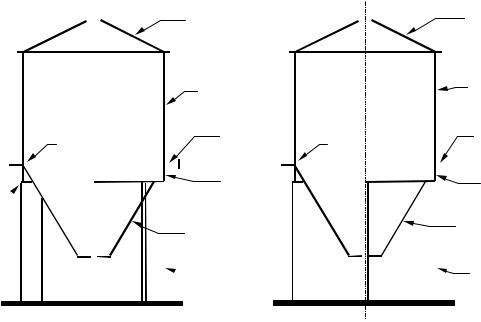
Figure 1.1: Terminology used in silo structures
1.5.19base ring: A base ring is a structural member that passes around the circumference of the structure at the base and provides means of attachment of the structure to a foundation or other element. It is required to ensure that the assumed boundary conditions are achieved in practice.
1.5.20ring girder or ring beam: A ring girder or ring beam is a circumferential stiffener which has bending stiffness and strength both in the plane of the circular section of a shell or the plan section of a rectangular structure and also normal to that plane. It is a primary load-carrying element, used to distribute local loads into the shell or box structure.
1.5.21continuous support: A continuously supported silo is one in which all positions around the circumference are supported in an identical manner. Minor departures from this condition (e.g. a small opening) need not affect the applicability of the definition.
1.5.22discrete support: A discrete support is a position in which a silo is supported using a local bracket or column, giving a limited number of narrow supports around the silo circumference. Four or six discrete supports are commonly used, but three or more than six are also found.
4
EN 1993-4-1:2007 (Е)
1.5.23 pyramidal hopper: A pyramidal hopper is used for the hopper section of a rectangular silo, in the form of an inverted pyramid. In this Standard, it is assumed that the geometry is simple, consisting of only four planar elements of trapezoidal shape.
1.6 Symbols used in Part 4.1 of Eurocode 3
The symbols used are based on ISO 3898: 1987.
1.6.1Roman upper case letters
Aarea of cross-section;
Cmembrane stretching stiffness;
Cbuckling coefficient;
D bending flexural rigidity;
EYoung’s modulus;
Fforce;
Gshear modulus;
Hheight of structure;
Isecond moment of area of cross-section;
It |
uniform torsion constant; |
Kflexural stiffness of wall panel;
L height of shell segment or stiffener;
M bending moment;
Naxial force;
Qfabrication tolerance quality of construction of a shell susceptible to buckling;
Rφ |
local radius at the crest or trough of a corrugation. |
1.6.2Roman lower case letters
acoefficient;
bwidth of plate or stiffener;
d crest to crest dimension of a corrugation;
eeccentricity of force or stiffener;
fy |
yield strength of steel; |
fu |
ultimate strength of steel; |
hseparation of flanges of ring girder;
jjoint efficiency factor for welded lap joints assessed using membrane stresses;
jequivalent harmonic of the design stress variation;
leffective length of shell in linear stress analysis;
lwavelength of a corrugation in corrugated sheeting;
lhalf wavelength of a potential buckle (height to be considered in calculation); m bending moment per unit width;
mx |
meridional bending moment per unit circumference; |
my |
circumferential bending moment per unit height of box; |
mθ |
circumferential bending moment per unit height of shell; |
mxy |
twisting shear moment per unit width of plate; |
mxθ |
twisting shear moment per unit width of shell; |
nmembrane stress resultant;
nnumber of discrete supports around silo circumference;
nx |
meridional membrane stress resultant per unit circumference; |
ny |
circumferential membrane stress resultant per unit height of box; |
nθ |
circumferential membrane stress resultant per unit height of shell; |
nxy |
membrane shear stress resultant per unit width of plate; |
nxθ |
membrane shear stress resultant per unit width of shell; |
5