- •Identify successors, feasible successors, and feasible distances.
- •Specify the addresses of the serial interfaces as shown in the topology diagram. Set the clock rate to 64 kb/s, and manually configure the interface bandwidth to 64 kb/s.
- •Step 2: Configure eigrp.
- •Step 3: Examine the eigrp topology table.
- •Step 4: Observe equal-cost load balancing.
- •Step 5: Analyze alternate eigrp paths not in the topology table.
- •If the r2 Serial0/0/1 interface were shut down, would eigrp route through r1 to get to 10.1.2.0/30? Why isn’t the switch to a new path a quick as it could be?
- •In this example, two packets were dropped during the cutover.
- •Step 6: Observe unequal-cost load balancing.
CCNPv7 ROUTE Lab 2-1, EIGRP Load Balancing

CCNPv7 ROUTE
Chapter 2 Lab 2-1, EIGRP Load Balancing Instructor Version
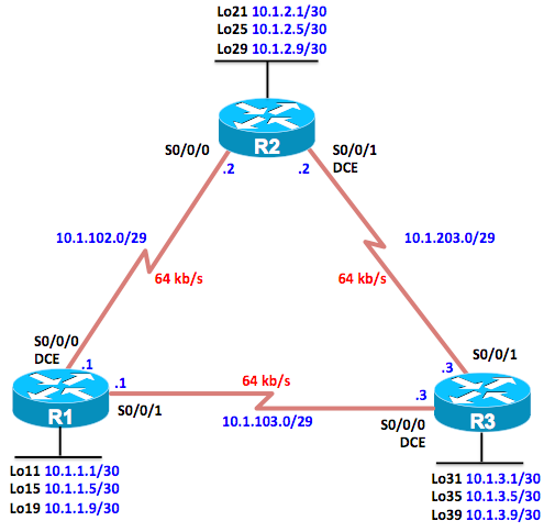
Topology

Objectives
-
Review a basic EIGRP configuration.
-
Explore the EIGRP topology table.
-
Identify successors, feasible successors, and feasible distances.
-
Use show and debug commands for the EIGRP topology table.
-
Configure and verify equal-cost load balancing with EIGRP.
-
Configure and verify unequal-cost load balancing with EIGRP.
Background
As a senior network engineer, you are considering deploying EIGRP in your corporation and want to evaluate its ability to converge quickly in a changing environment. You are also interested in equal-cost and unequal-cost load balancing because your network contains redundant links. These links are not often used by other link-state routing protocols because of high metrics. Because you are interested in testing the EIGRP claims that you have read about, you decide to implement and test on a set of three lab routers before deploying EIGRP throughout your corporate network.
Note: This lab uses Cisco 1941 routers with Cisco IOS Release 15.4 with IP Base. Depending on the Cisco IOS Software version, the commands available and output produced might vary from what is shown in this lab.
Required Resources
-
3 routers (Cisco IOS Release 15.2 or comparable)
-
Serial and Ethernet cables
Step 0: Suggested starting configurations.
-
Apply the following configuration to each router along with the appropriate hostname. The exec-timeout 0 0 command should only be used in a lab environment.
Router(config)# no ip domain-lookup
Router(config)# line con 0
Router(config-line)# logging synchronous
Router(config-line)# exec-timeout 0 0
Step 1: Configure the addressing and serial links.
-
Create three loopback interfaces on each router and address them as 10.1.X.1/30, 10.1.X.5/30, and 10.1.X.9/30, where X is the number of the router. Use the following table or the initial configurations located at the end of the lab.
|
Router |
Interface |
IP Address/Mask |
|
R1 |
Loopback11 |
10.1.1.1/30 |
|
R1 |
Loopback15 |
10.1.1.5/30 |
|
R1 |
Loopback19 |
10.1.1.9/30 |
|
R2 |
Loopback21 |
10.1.2.1/30 |
|
R2 |
Loopback25 |
10.1.2.5/30 |
|
R2 |
Loopback29 |
10.1.2.9/30 |
|
R3 |
Loopback31 |
10.1.3.1/30 |
|
R3 |
Loopback35 |
10.1.3.5/30 |
|
R3 |
Loopback39 |
10.1.3.9/30 |
R1(config)# interface Loopback 11
R1(config-if)# ip address 10.1.1.1 255.255.255.252
R1(config-if)# exit
R1(config)# interface Loopback 15
R1(config-if)# ip address 10.1.1.5 255.255.255.252
R1(config-if)# exit
R1(config)# interface Loopback 19
R1(config-if)# ip address 10.1.1.9 255.255.255.252
R1(config-if)# exit
R2(config)# interface Loopback 21
R2(config-if)# ip address 10.1.2.1 255.255.255.252
R2(config-if)# exit
R2(config)# interface Loopback 25
R2(config-if)# ip address 10.1.2.5 255.255.255.252
R2(config-if)# exit
R2(config)# interface Loopback 29
R2(config-if)# ip address 10.1.2.9 255.255.255.252
R2(config-if)# exit
R3(config)# interface Loopback 31
R3(config-if)# ip address 10.1.3.1 255.255.255.252
R3(config-if)# exit
R3(config)# interface Loopback 35
R3(config-if)# ip address 10.1.3.5 255.255.255.252
R3(config-if)# exit
R3(config)# interface Loopback 39
R3(config-if)# ip address 10.1.3.9 255.255.255.252
R3(config-if)# exit
