

Теория управления / Л4-Миль-Мур-СА / pics / 6-sequential logic-31
.pdfGeneral realization (program)
N |
|
Combinational circuit that |
|
M |
|
••• |
realizes |
|
|||
inputs |
••• |
||||
|
|
outputs |
|||
|
|
Output = f(input, old state) |
|
||
|
|
|
|
||
|
|
new state = h(input, old state) |
|
r digits |
|
|
|
|
|
||
r digits |
••• |
|
••• |
new state |
|
|
|
||||
old state |
|
|
|
|
|
|
|
D |
|
|
|
|
|
D |
••• |
|
|
|
|
clk |
|
||
|
|
|
|
||
|
|
••• |
|
|
D |
21 |
A.J. Han Vinck |

|
An example |
input |
output |
|
combinational |
Old-state |
new-state |
|
D |
|
memory |
|
D |
|
••• |
|
clock |
A.J. Han Vinck |
22 |
|
|
|
|
|
|
|

General finite state machine
Specified by: inputs
content of memory elements, called states transitions between states
outputs Analyzed by:
state transition graphs (Markov chains) state transition tables
A.J. Han Vinck |
23 |
|
|
|
|
|
|
|

Some history on finite state machines
the early application: to model the human thought process, whether in the brain or in a computer. (Warren McCulloch and Walter Pitts, "A Logical Calculus Immanent in Nervous Activity", 1943)
G.H. Mealy and E.F. Moore, generalized the theory to much more powerful machines in separate papers, published in 1955-56. The finite-state machines, the Mealy machine and the Moore machine, are named in recognition of their work.
Moore E. F.
Gedanken-experiments on Sequential Machines.
Automata Studies, Annals of Mathematical Studies, 34, 129–153.
Princeton University Press, Princeton, N.J.(1956). (thanks to Einstein)
GH Mealy. |
|
|
A method for synthesizing sequential circuits. Bell System Technical |
|
|
Journal, 35(5):1045—. 1079, 1955. |
A.J. Han Vinck |
24 |
|
||

There are 2 types of sequential machines
Moore
Mealy
Difference between Moore and Mealy state machines:
- In Mealy, output changes immediately when the input changes (faster) |
|
-Moore gives response in the next clock. |
|
-Mealy state machine uses in general less states than the Moore. |
25 |
A.J. Han Vinck |

Diagram of a Hopfield type network
26

we now look at:
1.the time or clock signal
2.state diagram/table with an example
3.state table minimization
A.J. Han Vinck |
27 |
|
|
|
|
|
|
|

D Q
FF-Timing revisited
clk Q‘
There is no problem when x(t) has full duty cycle
clock
x(t) |
1 |
0 |
1 |
0 |
u(t) |
0 |
1 |
0 |
1 |
The signal x(t) is delayed by 1 time unit
x(t) |
u(t) = x(t-1) |
clock
The content of the flip-flop is also called its state
The content can be observed by the output
A.J. Han Vinck |
28 |
|
|
|
|
|
|
|
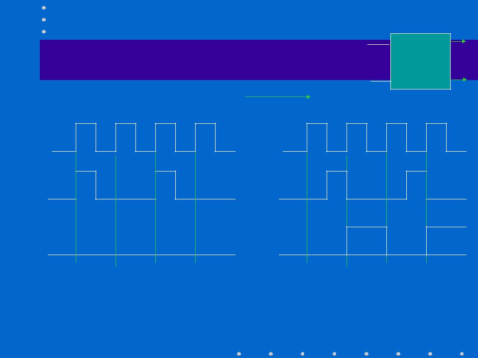
D Q
FF-Timing revisited
clk Q‘
time
We reconsider the timing for flip-flops
clock |
clock |
x(t) |
1 |
0 |
1 |
0 |
x(t) |
1 |
0 |
1 |
0 |
u(t) |
0 |
0 |
0 |
0 |
u(t) |
0 |
1 |
0 |
1 |
The signal x(t) must be present when the clock has a rising edge
A.J. Han Vinck |
29 |
|
|
|
|
|
|
|

D Q
FF-Timing example
clk Q‘
in |
|
s1 |
s0 |
|
|||
|
|
|
|
|
0 |
|
0 |
|
|
|
|
time |
out |
|
The collective content of the flip-flops
is also called the state of the machine
clock |
The signal s0(t) = s1(t-1) |
in(t) |
1 |
0 |
1 |
0 s0(t) |
0 |
0 |
1 |
0 |
s1(t) |
0 |
1 |
0 |
1 out(t) |
1 |
1 |
0 |
1 |
A.J. Han Vinck |
30 |
|
|
|
|
|
|
|