

Activity 3.5.4: Subnetting Scenario 3
Topology Diagram
Addressing Table
|
Device |
Interface |
IP Address |
Subnet Mask |
Default Gateway |
|
|
|
|
|
|
|
|
Fa0/0 |
|
|
N/A |
|
HQ |
|
|
|
|
|
S0/0/0 |
|
|
N/A |
|
|
|
|
|
|
|
|
|
S0/0/1 |
|
|
N/A |
|
|
|
|
|
|
|
|
Fa0/0 |
|
|
N/A |
|
|
|
|
|
|
|
BRANCH1 |
Fa0/1 |
|
|
N/A |
|
|
|
|
|
|
|
S0/0/0 |
|
|
N/A |
|
|
|
|
|
||
|
|
|
|
|
|
|
|
S0/0/1 |
|
|
N/A |
|
|
|
|
|
|
|
|
Fa0/0 |
|
|
N/A |
|
|
|
|
|
|
|
BRANCH2 |
Fa0/1 |
|
|
N/A |
|
|
|
|
|
|
|
|
S0/0/0 |
|
|
N/A |
|
|
|
|
|
|
|
|
S0/0/1 |
|
|
N/A |
|
|
|
|
|
|
|
PC1 |
NIC |
|
|
|
|
|
|
|
|
|
|
PC2 |
NIC |
|
|
|
|
|
|
|
|
|
|
PC3 |
NIC |
|
|
|
|
|
|
|
|
|
|
PC4 |
NIC |
|
|
|
|
|
|
|
|
|
|
PC5 |
NIC |
|
|
|
|
|
|
|
|
|
All contents are Copyright © 1992–2007 Cisco Systems, Inc. All rights reserved. This document is Cisco Public Information. |
Page 1 of 3 |

CCNA Exploration |
|
Routing Protocols and Concepts: |
|
Introduction to Dynamic Routing Protocols |
Activity 3.5.4: Subnetting Scenario 3 |
Learning Objectives
Upon completion of this lab, you will be able to:
•Determine the number of subnets needed.
•Determine the number of hosts needed.
•Design an appropriate addressing scheme.
•Conduct research to find a possible solution.
Scenario
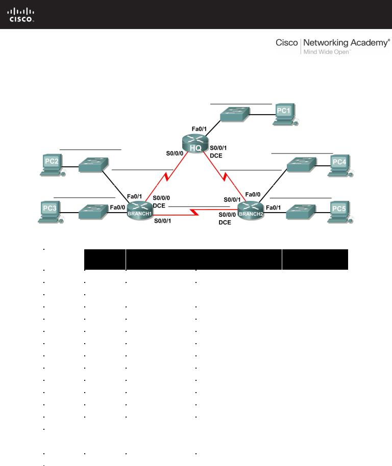
In this lab, you have been given the network address 192.168.1.0/24 to subnet and provide the IP addressing for the network shown in the Topology Diagram. The network has the following addressing requirements:
•The BRANCH1 LAN 1 will require 15 host IP addresses.
•The BRANCH1 LAN 2 will require 15 host IP addresses.
•The BRANCH2 LAN 1 will require 15 host IP addresses.
•The BRANCH2 LAN 2 will require 15 host IP addresses.
•The HQ LAN will require 30 host IP addresses.
•The link from HQ to BRANCH1 will require an IP address for each end of the link.
•The link from HQ to BRANCH2 will require an IP address for each end of the link.
•The link from HQ to Branch 3 will require an IP address for each end of the link.
Task 1: Examine the Network Requirements.
Examine the network requirements and answer the questions below. Keep in mind that IP addresses will be needed for each of the LAN interfaces.
How many subnets are needed? __________
What is the maximum number of IP addresses that are needed for a single subnet? __________
How many IP addresses are needed for each of the branch LANs? __________
What is the total number of IP addresses that are needed? __________
Task 2: Design an IP Addressing Scheme
Subnet the 192.168.1.0/24 network into the appropriate number of subnets.
Can the 192.168.1.0/24 network be subnetted to fit the network requirements? __________
If the “number of subnets” requirement is met, what is the maximum number of hosts per subnet?
__________
If the “maximum number of hosts” requirement is met, what is the number of subnets that will be available to use? __________
All contents are Copyright © 1992–2007 Cisco Systems, Inc. All rights reserved. This document is Cisco Public Information. |
Page 2 of 3 |

CCNA Exploration |
|
Routing Protocols and Concepts: |
|
Introduction to Dynamic Routing Protocols |
Activity 3.5.4: Subnetting Scenario 3 |
Task 3: Reflection
You do not have enough address space to implement an addressing scheme. Research this problem and propose a possible solution. Increasing the size of your original address space is not an acceptable solution. (Hint: We will discuss solutions to this problem in Chapter 6.)
____________________________________________________________________________
____________________________________________________________________________
____________________________________________________________________________
Attempt to implement your solution using Packet Tracer. Successful implementation of a solution requires that:
•Only the 192.168.1.0/24 address space is used.
•PCs and routers can ping all IP addresses.
All contents are Copyright © 1992–2007 Cisco Systems, Inc. All rights reserved. This document is Cisco Public Information. |
Page 3 of 3 |
3.6.1: Packet Tracer Skills Integration Challenge Activity
Topology Diagram
All contents are Copyright © 1992–2007 Cisco Systems, Inc. All rights reserved. This document is Cisco Public Information. |
Page 1 of 4 |
CCNA Exploration |
|
Routing Protocols and Concepts: |
|
Introduction to Dynamic Routing Protocols |
3.6.1: Packet Tracer Skills Integration Challenge Activity |
Addressing Table
|
Device |
Interface |
IP Address |
Subnet Mask |
|
|
|
|
|
|
|
Fa0/0 |
|
|
|
|
|
|
|
|
|
Fa0/1 |
|
|
|
|
|
|
|
|
HQ |
S0/0/0 |
10.0.0.1 |
255.255.255.252 |
|
|
|
|
|
|
S0/0/1 |
10.0.0.5 |
255.255.255.252 |
|
|
|
|||
|
|
|
|
|
|
|
S0/1/0 |
10.0.0.9 |
255.255.255.252 |
|
|
|
|
|
|
|
S0/1/1 |
209.165.201.2 |
255.255.255.252 |
|
|
|
|
|
|
|
Fa0/0 |
|
|
|
|
|
|
|
|
|
Fa0/1 |
|
|
|
B1 |
|
|
|
|
Fa1/0 |
|
|
|
|
|
|
|
|
|
|
Fa1/1 |
|
|
|
|
|
|
|
|
|
S0/0/0 |
10.0.0.2 |
255.255.255.252 |
|
|
|
|
|
|
|
Fa0/0 |
|
|
|
|
|
|
|
|
|
Fa0/1 |
|
|
|
B2 |
|
|
|
|
Fa1/0 |
|
|
|
|
|
|
|
|
|
|
Fa1/1 |
|
|
|
|
|
|
|
|
|
S0/0/0 |
10.0.0.6 |
255.255.255.252 |
|
|
|
|
|
|
|
Fa0/0 |
|
|
|
|
|
|
|
|
|
Fa0/1 |
|
|
|
B3 |
|
|
|
|
Fa1/0 |
|
|
|
|
|
|
|
|
|
|
Fa1/1 |
|
|
|
|
|
|
|
|
|
S0/0/0 |
10.0.0.10 |
255.255.255.252 |
|
|
|
|
|
|
ISP |
S0/0/0 |
209.165.201.1 |
255.255.255.252 |
|
|
|
|
|
|
Fa0/0 |
209.165.200.225 |
255.255.255.252 |
|
|
|
|||
|
|
|
|
|
|
Web |
NIC |
209.165.200.226 |
255.255.255.252 |
|
Server |
|||
|
|
|
|
|
|
|
|
|
|
Objectives
•Design and document an addressing scheme based on requirements.
•Select appropriate equipment and cable the devices.
•Apply a basic configuration to the devices.
•Configure static and default routing.
•Verify full connectivity between all devices in the topology.
All contents are Copyright © 1992–2007 Cisco Systems, Inc. All rights reserved. This document is Cisco Public Information. |
Page 2 of 4 |

CCNA Exploration |
|
Routing Protocols and Concepts: |
|
Introduction to Dynamic Routing Protocols |
3.6.1: Packet Tracer Skills Integration Challenge Activity |
Task 1: Design and document an addressing scheme.
Step 1: Design an addressing scheme.
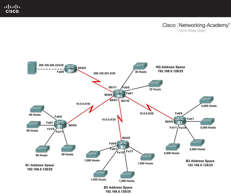
Based on the network requirements shown in the topology, design an appropriate addressing scheme.
•The HQ, B1, B2, and B3 routers each have an address space. Subnet the address space based on the host requirements.
•For each address space, assign subnet zero to the Fa0/0 LAN, subnet 1 to the Fa0/1, and so on.
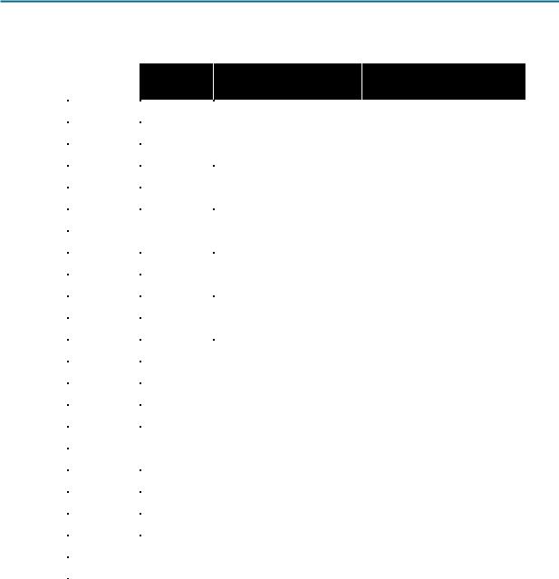
Step 2: Document the addressing scheme.
•Use the table provided in the printed instructions to document the IP addresses and subnet masks. Assign the first IP address to the router interface.
•For the WAN links, assign the first IP address to HQ.
Task 2: Select equipment and cable devices.
Step 1: Select the necessary equipment.
Select the remaining devices you will need and add them to the working space inside Packet Tracer. Use the interface labels as a guide as to where to place the devices.
Step 2: Finish cabling the devices.
Cable the networks according to the topology taking care that interfaces match the topology and your documentation in Task 1. HQ is the DCE side for B1, B2 and B3. ISP is the DCE for the link to HQ.
Task 3: Apply a basic configuration.
Using your documentation, configure the routers with basic configurations including addressing. Use cisco as the line passwords and class as the secret password. Use 64000 as the clock rate.
Task 4: Configure static and default routing
Configure static and default routing using the exit interface argument.
•HQ should have three static routes and one default route.
•B1, B2, and B3 should have one default route.
•ISP should have seven static routes. This will include the three WAN links between HQ and the branch routers B1, B2, and B3.
All contents are Copyright © 1992–2007 Cisco Systems, Inc. All rights reserved. This document is Cisco Public Information. |
Page 3 of 4 |
CCNA Exploration |
|
Routing Protocols and Concepts: |
|
Introduction to Dynamic Routing Protocols |
3.6.1: Packet Tracer Skills Integration Challenge Activity |
Task 5: Test connectivity and examine the configuration.
Step 1: Test connectivity.
You should now have end-to-end connectivity. Use ping to test connectivity across the network. Each router should be able to ping all other router interfaces and the Web Server.
Use extended ping to test LAN connectivity to the Web Server. For example, the test the Fa0/0 interface on B1, you would do the following:
B1#ping
Protocol [ip]:
Target IP address: 209.165.200.226 Repeat count [5]:
Datagram size [100]: Timeout in seconds [2]: Extended commands [n]: yes
Source address or interface: 192.168.1.1 Type of service [0]:
Set DF bit in IP header? [no]: Validate reply data? [no]: Data pattern [0xABCD]:
Loose, Strict, Record, Timestamp, Verbose[none]: Sweep range of sizes [n]:
Type escape sequence to abort.
Sending 5, 100-byte ICMP Echos to 209.165.200.226, timeout is 2 seconds: Packet sent with a source address of 192.168.1.1
!!!!!
Success rate is 100 percent (5/5), round-trip min/avg/max = 67/118/138 ms
Troubleshoot until pings are successful.
Step 2: Examine the configuration.
Use verification commands to make sure your configurations are complete.
All contents are Copyright © 1992–2007 Cisco Systems, Inc. All rights reserved. This document is Cisco Public Information. |
Page 4 of 4 |